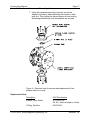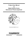
1
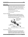
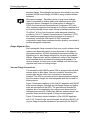
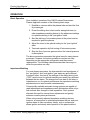
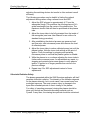
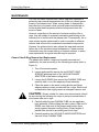
Product User Manual ♦ Model GA610x Series Downstream Plasma Applicator Document # 930027, Rev. 2 P.O. Box 580816 ♦ Modesto, CA 95358 www.2450mhz.com Product User Manual Model GA610x Series Downstream Plasma Applicator REV. 2 REVISION HISTORY DESCRIPTION ADDED OPTIONAL SPACERS Page 2 DATE 14JAN04 APPROVAL JFG WARRANTY Products manufactured and sold by Gerling Applied Engineering, Inc. (“GAE”) are warranted to be free of defects in materials and workmanship under normal use and service for a period of twelve (12) months from the date of original shipment. GAE’s obligation under this warranty is limited to repairing or replacing, at GAE’s option, all non-consumable component parts. Consumable parts are specifically excluded from this warranty and may include, but are not be limited to, magnetrons, fuses, lamps, seals, o-rings, v-belts, and fluids. All warranty repairs are to be done at GAE’s facility or as otherwise authorized by GAE. All shipping charges for warranty repair or replacement are the purchaser’s responsibility unless otherwise agreed to by GAE. This warranty supercedes all other warranties, expressed or implied. No warranty is given covering the product for any particular purpose other than as covered by the applicable product specifications. GAE assumes no liability in any event for incidental or consequential damages, financial losses, penalties or other losses incurred in conjunction with the use of GAE products. DOCUMENT CONVENTIONS NOTE: Means the reader should take note. Notes contain helpful information, suggestions, or references to other sections, chapters, or documents. CAUTION: Means the reader should be careful. You are doing something that might result in equipment damage or loss of data. WARNING: Means danger. A situation exists that could cause bodily injury or death. All personnel must be aware of the hazards involved with high voltage electrical circuitry and high power microwave devices. 2003-2004 Gerling Applied Engineering, Inc. Modesto, CA Product User Manual Model GA610x Series Downstream Plasma Applicator Page 3 WARNING All waveguide applicators manufactured by GAE, Inc. are intended for use with other equipment capable of producing a microwave field that is potentially hazardous to operating personnel. They must never be connected or operated in a manner that allows a field in excess of 10 milliwatts per square centimeter to be generated in an area accessible to operating personnel. Contact GAE, Inc. for technical support prior to installation and/or operation of these units if there is any question or concern about microwave leakage. All waveguide flange and electrical cable connections throughout the system must be secure prior to operation. Never operate the microwave generator without a properly rated absorbing load attached. To ensure safe operation and prevent microwave leakage, the equipment must be periodically inspected and maintained as required or recommended. 2003-2004 Gerling Applied Engineering, Inc. Modesto, CA Product User Manual Model GA610x Series Downstream Plasma Applicator Page 4 TABLE OF CONTENTS EQUIPMENT DESCRIPTION ......................................................................................... 5 General Specifications 5 INSTALLATION .............................................................................................................. 6 Preliminary Inspection Waveguide Configuration Waveguide Flange Connections Flange Alignment Pins Vacuum Flange Connections Water Fitting Connections 6 6 6 7 7 9 OPERATION................................................................................................................. 10 Basic Operation Impedance Matching Ultraviolet Radiation Safety 10 10 11 MAINTENANCE............................................................................................................ 12 Plasma Tube/O-Ring Removal and Replacement Replacement Parts 12 13 2003-2004 Gerling Applied Engineering, Inc. Modesto, CA Product User Manual Model GA610x Series Downstream Plasma Applicator Page 5 EQUIPMENT DESCRIPTION The GA610x Downstream Plasma Applicator was designed as general purpose tool for plasma process development. It features a quartz plasma tube fitted between standard stainless steel vacuum fittings which are easily disassembled for tube replacement. Standard Swagelok® fittings are provided for water cooling as well as waveguide perforations for viewing and/or additional forced air cooling of the plasma tube. To facilitate process development for different gas recipes, the waveguide is designed with flanges at both ends. This allows connection to a sliding short circuit (such as model GA1205) which helps to optimize microwave coupling as the load impedance varies with gas recipe. For basic installations a fixed position short can also be installed in place of the sliding short circuit. Optional spacer sections can also be installed to further isolate the o-rings from the internal source of heat, thus improving operation with higher temperature processes. A popular feature for laboratory applications is the quick-connect waveguide flange style which allows rapid assembly and disassembly of adjacent waveguide components using single screw clamps (model GA8401). General Specifications Waveguide Flanges Frequency Input Power Vacuum Flanges O-rings Cooling Water Water Fittings Construction Finish WR284 UG-584/U with taper 2450 MHz nominal 1.5 kW continuous max. (process dependent and may require additional cooling) GA6101: ISO NW40 GA6102: 2-3/4” Conflat® Parker Paroflour® 0.5 gpm min., 70 psi max., 50°C inlet max. ¼” copper tubing with Swagelok® nuts and ferrules Waveguide: Dip brazed aluminum Vacuum flanges: Type 304 stainless steel Water cooling lines: Copper and brass Chemical film; Black textured paint 2003-2004 Gerling Applied Engineering, Inc. Modesto, CA Product User Manual Model GA610x Series Downstream Plasma Applicator Page 6 INSTALLATION Preliminary Inspection Upon arrival at the installation site the GA610x series Downstream Plasma Applicator (“DPA”) should be thoroughly inspected for damage or wear caused during shipping. Any visible damage to the packaging material or the applicator itself should be noted and reported immediately to the shipping company in accordance with standard claims procedures. The following components are included: a) GA610x series Downstream Plasma Applicator b) Product User Manual Waveguide Configuration The DPA can be connected to and used with any common waveguide component having a compatible flange (see below). Mounting can be in any convenient position and orientation with either flange positioned towards the microwave generator. Ideally, the DPA should be located as close to the tuner as possible. Figure 1 illustrates a typical waveguide configuration. Figure 1 – Typical waveguide configuration for downstream plasma processing. Waveguide Flange Connections Both flanges of the DPA must be properly connected to another waveguide component. Bolts and nuts must be installed at all flange bolt holes on both flanges prior to operation. Models GA6101 and GA6102 are available with flanges designed for used with the GA8401 Quick-Release clamp when connected to another similarly 2003-2004 Gerling Applied Engineering, Inc. Modesto, CA Product User Manual Model GA610x Series Downstream Plasma Applicator Page 7 designed flange. These flanges can also be connected to any other standard WR284 round flange (UG-584/U) using suitable fastener hardware. Microwave Leakage – Regulatory limits for microwave leakage relate to standards for human safety and interference with other electronic devices. Standards for human safety as adopted by OSHA, the International Electrotechnical Commission (IEC) and other regulatory agencies limit leakage to 5 mW/cm2 measured at 5 cm from the leakage source under normal operating conditions, and 10 mW/cm2 at 5 cm from the source under abnormal operating conditions. The U.S. Federal Communications Commission (FCC) has established regulations limiting the emission of energy at frequencies outside the ISM bands. All GAE waveguide components meets these requirements when properly connected to another waveguide component. Flange Alignment Pins Each waveguide flange connection that uses a quick-release clamp requires two alignment pins for proper alignment of the adjacent waveguide sections. All GAE waveguide components include one alignment pin for each flange designed for use with quick-release clamps. Alignment pins can be installed into either of two threaded holes centered above and below the waveguide broadwalls. For obvious reasons, the pins must not be installed such that they are opposite each other on mating flanges. Vacuum Flange Connections The standard model GA610x series DPA is designed with identical vacuum ports on both sides. One port is used for introducing the process gas and the other is for connection to the process chamber. The DPA is symmetrical about the waveguide centerline, thus the vacuum flanges are interchangeable and can be used for either purpose. Figure 2 illustrates installation of the GA6101 applicator with NW40 style vacuum flanges. Standard vacuum flange clamps and gasket seals are provided with the DPA. The gas feed and chamber lid adapters are to be supplied by the customer and shown here for reference purposes only. While many different adapter designs are possible, those shown are typical of many process systems. Figure 3 illustrates a similar installation of the GA6102 applicator with 2-3/4” Conflat style vacuum flanges. As with the GA6101, all vacuum flange connection hardware is provided with the GA6102. 2003-2004 Gerling Applied Engineering, Inc. Modesto, CA Product User Manual Model GA610x Series Downstream Plasma Applicator Page 8 Figure 2 – Typical GA6101 vacuum flange connections. Figure 3 – Typical GA6102 vacuum flange connections. 2003-2004 Gerling Applied Engineering, Inc. Modesto, CA Product User Manual Model GA610x Series Downstream Plasma Applicator Page 9 Water Fitting Connections Connections for water cooling are made to two ¼” Swagelok® compression fittings. The source of water can be connected to either fitting. The fitting must be torqued according to Swagelok® specifications to ensure a leak-free connection. Care should be taken to prevent debris from falling into the fitting holes while disconnected. CAUTION: Use wrench tools on both sides of the fitting connection to immobilize the mating fitting while tightening the fitting nut. Failure to secure the mating fitting while tightening can cause damage to the copper water tubing protruding from the cooling block. 2003-2004 Gerling Applied Engineering, Inc. Modesto, CA Product User Manual Model GA610x Series Downstream Plasma Applicator Page 10 OPERATION Basic Operation Once installed, operation of the GA610x series Downstream Plasma Applicator consists of the following basic steps: 1. Establish a vacuum within the plasma tube and start the flow of process gas. 2. Preset the sliding short circuit and/or waveguide tuner (or other impedance matching device) to the adjustment settings for optimal matching in the “pre-ignition” state. 3. Start the delivery of microwave power at the power level as required to ignite the plasma. 4. Adjust the tuner to the optimal setting for the “post-ignition” state. 5. Terminate operation by first turning off microwave power. 6. Stop the flow of process gas and return the internal pressure to atmospheric. The above procedure represents the typical case for many plasma processes. However, the actual procedures involved can vary depending on the waveguide configuration and the process requirements. The following subsections describe some ways in which the procedure can vary. Impedance Matching For most plasma processes, the characteristic load impedances of the “pre-ignition” and “post-ignition” gas states are quite different from each other. As a result, the settings of the sliding short circuit (“SSC”) and/or tuner for optimal matching are usually very different between the two states. The change from one state to the other is instantaneous, so for optimal performance the impedance matching adjustments must also be made instantaneously. Commercially available automatic tuning systems are capable of rapid adjustments and impedance match optimization within only a few seconds after changes in load impedance. Such systems eliminate the need for manual tuner adjustments and greatly enhance overall system performance. When using manually adjusted impedance matching devices, however, a compromise in optimization between the pre- and postignition states is often necessary. Ideally, such a compromise allows ignition and steady state operation of the plasma without 2003-2004 Gerling Applied Engineering, Inc. Modesto, CA Product User Manual Model GA610x Series Downstream Plasma Applicator Page 11 adjusting the matching devices but results in often reduced overall efficiency. The following procedure may be helpful in finding the optimal adjustment settings when using a manual tuner and SSC. 1. Adjust the SSC plunger to approximately 4.3” from the waveguide flange. This positions the shorting plane at 3/4 – guide wavelength from the center of the plasma tube. The maximum electric field will then be positioned at the plasma tube. 2. Adjust the tuner stubs to be fully retracted from the inside of the waveguide (see tuner User Manual for an outline of a standard tuning procedure). 3. After establishing the desired process gas pressure level and flow rate, start microwave power and observe the level of reflected power. 4. Adjust the tuner stubs to reduce reflected power just until the plasma ignites. Note the tuner stub settings at the point of ignition. Verify the settings by stopping and restarting microwave power to see that the plasma ignition is reliable. 5. While the plasma is on, continue adjusting the tuner stubs to further reduce reverse power. As adjustments are made, try stopping and restarting microwave power to verify plasma ignition. If ignition is no longer possible then return to the previous settings. 6. Repeat step 5 for SSC adjustments instead of tuner adjustments. Ultraviolet Radiation Safety The plasma generated within the GA610x series applicator will itself generate ultraviolet radiation. The intensity of the radiation depends on the plasma intensity, but in most cases it can cause burns from prolonged exposure. The most common injury is damage to the eyes after extended periods of direct viewing of the plasma. For safety of operating personnel, viewing the plasma should be done only through an ultraviolet-absorbing material such as Pyrex®. In any case, the viewing time periods should be minimized. 2003-2004 Gerling Applied Engineering, Inc. Modesto, CA Product User Manual Model GA610x Series Downstream Plasma Applicator Page 12 MAINTENANCE The GA610x series Downstream Plasma Applicator operates at extremely high internal temperatures due to the hot ionized gases flowing in the plasma tube. Water cooling helps to dissipate the heat near the o-ring seals, while optional spacer sections help to further isolate these temperature limited components from the source of heat. However, regardless of the amount of external cooling of the orings, they are subject to eventual overheating and burning at the internal point of contact with the plasma tube. Consequently, the orings require regular replacement in order to provide an effective vacuum seal and are thus considered consumable components. Likewise, the plasma tube is also subject the wear and eventual failure due to the extreme internal temperature. Certain process chemistries may also cause etching on internal surfaces, in which case replacement at regular intervals may be required. Plasma Tube/O-Ring Removal and Replacement The plasma tube and/or o-rings can be easily removed and replaced by the user according to the following procedure (refer to Figure 5): 1. Turn off microwave power. 2. Loosen and carefully remove the six SOCKET HEAD SCREWS attaching each of the VACUUM FLANGE ADAPTERS to the water cooling block. 3. Loosen the O-RINGS from around the PLASMA TUBE and carefully slide it out of the applicator body assembly. 4. Clean the areas on the water cooling blocks and flange adapters where contact is made with the o-rings. Remove all contamination that might prevent an adequate vacuum seal. CAUTION: Gloves suitable for clean-room environments should be worn during the following two steps to prevent contamination of the plasma tube and o-rings. 5. Carefully slide the new PLASMA TUBE into the applicator body assembly. While holding the tube in place, slide new ORINGS over both ends of the plasma and position them snugly against the water cooling blocks. Equal lengths of plasma tube should be protruding past the o-rings. 6. Carefully position the VACUUM FLANGE ADAPTERS over the ends of the PLASMA TUBE. 2003-2004 Gerling Applied Engineering, Inc. Modesto, CA Product User Manual Model GA610x Series Downstream Plasma Applicator Page 13 7. Using the hardware previously removed, secure the adapters in place by hand-tightening the screws on both ends first. Then tighten the screws evenly at both ends by alternating diametrically until the adapters are secured. Figure 4 – Exploded view for removal and replacement of the plasma tube and o-rings. Replacement Parts Description GAE Part Number Plasma Tube, Quartz 911142-XX.XX XX.XX = Nominal length in inches O-Ring, Parofluor 420103-214 2003-2004 Gerling Applied Engineering, Inc. Modesto, CA