1
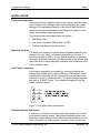
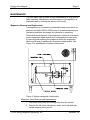
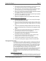
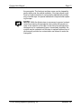
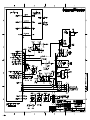
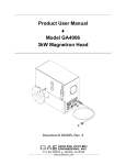
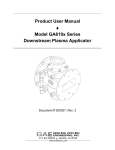
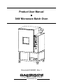
Product User Manual ♦ 3kW Microwave Batch Oven Document # 930057, Rev. 1 P.O. Box 580816 ♦ Modesto, CA 95358 www.2450mhz.com Product User Manual 3kW Microwave Batch Oven REV. 1 REVISION HISTORY DESCRIPTION PROTOTYPE RELEASE Page 2 DATE 04JAN05 APPROVAL JFG WARRANTY Products manufactured and sold by Gerling Applied Engineering, Inc. (“GAE”) are warranted to be free of defects in materials and workmanship under normal use and service for a period of twelve (12) months from the date of original shipment. GAE’s obligation under this warranty is limited to repairing or replacing, at GAE’s option, all nonconsumable component parts. Consumable parts are specifically excluded from this warranty and may include, but are not be limited to, magnetrons, fuses, lamps, seals, orings, v-belts, and fluids. All warranty repairs are to be done at GAE’s facility or as otherwise authorized by GAE. All shipping charges for warranty repair or replacement are the purchaser’s responsibility unless otherwise agreed to by GAE. This warranty supercedes all other warranties, expressed or implied. No warranty is given covering the product for any particular purpose other than as covered by the applicable product specifications. GAE assumes no liability in any event for incidental or consequential damages, financial losses, penalties or other losses incurred in conjunction with the use of GAE products. DOCUMENT CONVENTIONS NOTE: Means the reader should take note. Notes contain helpful information, suggestions, or references to other sections, chapters, or documents. CAUTION: Means the reader should be careful. You are doing something that might result in equipment damage or loss of data. WARNING: Means danger. A situation exists that could cause bodily injury or death. All personnel must be aware of the hazards involved with high voltage electrical circuitry and high power microwave devices. 2005 Gerling Applied Engineering, Inc. Modesto, CA Product User Manual 3kW Microwave Batch Oven Page 3 WARNING The microwave oven described in this manual is capable of producing a microwave field that is potentially hazardous to operating personnel. The unit must never be connected or operated in a manner that allows a field in excess of 10 milliwatts per square centimeter to be generated in an area accessible to operating personnel. Contact GAE, Inc. for technical support prior to installation and/or operation of these units if there is any question or concern about microwave leakage. All electrical cable connections must be secure prior to operation. Never operate the microwave oven without a properly rated absorbing load inside the oven cavity. To ensure safe operation and prevent microwave leakage, the equipment must be periodically inspected and maintained as required or recommended. 2005 Gerling Applied Engineering, Inc. Modesto, CA Product User Manual 3kW Microwave Batch Oven Page 4 TABLE OF CONTENTS EQUIPMENT DESCRIPTION ....................................................................................... 5 General Specifications Attachments 5 6 INSTALLATION ............................................................................................................. 7 Preliminary Inspection Mounting Position Line Power Connection External Interlock Connection Water Fitting Connections Exhaust Duct Connection 7 7 7 7 8 8 OPERATION .................................................................................................................. 9 Initial Start-up Standby Mode Fault Mode Operate Mode Microwave Power Adjustment (Manual) Process Control Operation (Automatic) 9 9 9 9 10 10 MAINTENANCE ........................................................................................................... 11 Magnetron Removal and Replacement 11 Magnetron Head Removal and Replacement Magnetron Removal and Replacement 11 12 Cleaning the Oven Cavity 12 Waveguide Feed Port Cover 12 2005 Gerling Applied Engineering, Inc. Modesto, CA Product User Manual 3kW Microwave Batch Oven Page 5 EQUIPMENT DESCRIPTION The microwave oven described in this manual is designed for industrial processing and laboratory research applications. Up to 3kW of microwave power operating a 2.45 GHz is delivered to a 36 ft3 oven chamber in a compact portable system. Microwave power is generated by a high performance 3kW variable microwave generator and delivered to the cavity using standard waveguide components that ensure high reliability and stable operation. A waveguide isolator protects the microwave generator from the damaging effects of reflected microwave power. Power couplers are provided with meters for monitoring actual forward and reflected microwave power. The oven chamber incorporates a mode stirrer to enhance heating uniformity. Cavity features include a large access door with view port, inlet and outlet ventilation ports, an outlet blower for forced ventilation, internal air circulation fans and a sturdy rack for product support. The cavity is supported by a welded structural steel frame with locking swivel casters for easy portability. Complete system functionality is controlled locally by manual and automatic programmable controls. All system controls are located on a front panel and include meters for monitoring forward and reflected microwave power. A programmable process controller enables multi-stage control of a variety of industrial processes. General Specifications Microwave Frequency 2.45 GHz +/- 30 MHz Microwave Power 3000 Watts rated output Power Control Continuously variable from 10 to 100% Input Power 190-250 VAC, 50/60 Hz, 3-Phase, 16 Amps/phase (@ 208 VAC) Cavity Features Product support rack, internal air circulation fans, view port, mode stirrer Cavity Ventilation Inlet and outlet ducts with outlet high-temp blower Oven Interlocks Oven door; water flow, external (customer) device, microwave generator Local Controls Main circuit breaker (toggle) Emergency Off (pushbutton, twist to reset) System Start/Stop (pushbuttons) Microwave Start/Stop (pushbuttons) Microwave Power Adjust (multi-turn dial) Manual/Automatic (toggle switch) 2005 Gerling Applied Engineering, Inc. Modesto, CA Product User Manual 3kW Microwave Batch Oven Local Indicators Page 6 Line Power System On System Ready Microwave On Fault Door Interlock Water Flow Interlock External Interlock Forward Microwave Power (analog meter) Reflected Microwave Power (analog meter) Line Power Connector NEMA locking style L15-20P flanged inlet Cooling Water Flow 1.0 gpm nominal (0.5 gpm minimum), 70 psig maximum Water Connections ¼” NPT-Female brass fittings Cavity Dimensions 36” wide x 48” high x 36” deep Overall Dimensions 46” wide x 73” high x 38” deep Weight 500 lbs (approx.) Document Number Description 911841 Outline Drawing, 3kW Batch Oven 911920 Schematic Diagram, 3kW Batch Oven 912018 Schematic Diagram, 3kW Magnetron Head n/a User Manual, E5AK-T Process Controller n/a User Manual, SM1150 Power Generator Attachments 2005 Gerling Applied Engineering, Inc. Modesto, CA Product User Manual 3kW Microwave Batch Oven Page 7 INSTALLATION Preliminary Inspection Upon arrival at the installation site the oven system should be thoroughly inspected for damage caused during shipping. Any visible damage to the packaging material or the system itself should be noted and reported immediately to the shipping company in accordance with standard claims procedures. The following items are supplied with the system: 1. 3kW Batch Oven 2. Line power connector, NEMA style L15-20R 3. Product User Manual (this document) Mounting Position The batch oven system is supplied as an integrated assembly consisting of the oven cavity, microwave generator and controls. It must be mounted upright on a level surface capable of supporting its weight. Sufficient clearance must be provided at the left side and rear of the oven to allow adequate ventilation and connection to the outlet ventilation duct. Line Power Connection Line power is supplied to the system by connecting through the locking style flanged inlet located at the rear of the system. A mating connector is provide with the system and must be wired to the customer’s source of electrical power. The recommended minimum wire size is 14 AWG. Figure 1 is a schematic diagram of the line power connector wiring. Figure 1, Line power wiring connections. External Interlock Connection A connector is located on the rear panel of the system for connecting a remote interlock device. The external interlock device must have dry contacts that are closed when the interlock function is satisfied. Connection is made between contacts 1 and 2 on this con- 2005 Gerling Applied Engineering, Inc. Modesto, CA Product User Manual 3kW Microwave Batch Oven Page 8 nector. The mating connector with spare crimp pins is also provided. Figure 2 is a schematic diagram of the external interlock connector wiring. Figure 2, External interlock device connection. Water Fitting Connections Standard 1/4 NPT female brass fittings are provided at the rear of the system. The source and drain must be connected to the respective fittings marked INLET and OUTLET. It is recommended that a thread sealant such as Teflon pipe thread tape be used to ensure a leak-free connection. Care should be taken to prevent debris from entering the fitting holes. Exhaust Duct Connection The system is shipped with the exhaust duct removed from the outlet of the exhaust blower. The duct must be reinstalled using the four sets of fasteners provided. Note that the folded edge of the duct flange is positioned towards the oven cavity. Figure 3 illustrates the duct installation. A suitable 4” flexible hose may then be connected to the exhaust duct. Figure 3, Installation of the blower exhaust duct. 2005 Gerling Applied Engineering, Inc. Modesto, CA Product User Manual 3kW Microwave Batch Oven Page 9 OPERATION Initial Start-up After connecting line power to the system as described in the previous section, the main circuit breaker must be turned on in order to provide line power to the system. The presence of line power is then indicated by the LINE POWER indicator on the front panel. If the EMERGENCY OFF (EMO) switch is in the normal (on) position and the DOOR, WATER FLOW and EXTERNAL interlock functions are satisfied then the respective front panel interlock indicators will be on at this time. Standby Mode When line power is present and the EMO switch is in the normal position, the system may be placed into Standby mode by momentarily pressing the SYSTEM START pushbutton. In this condition the SYSTEM ON indicator on the front panel will be on and line power will be provided to the microwave generator and cavity blower. If all of the interlock functions are satisfied the microwave generator then begins a warm-up period during which the magnetron filament is heated to its normal operating temperature. After the brief (5-10 seconds) warm-up period the SYSTEM READY indicator turns on. Pressing the SYSTEM STOP or the EMO pushbuttons at any time will immediately turn off the system and stop microwave power from being generated. Fault Mode If any of the interlock functions become disabled any time after pressing the SYSTEM START switch, or the microwave generator fails for any reason, the FAULT indicator will turn on, microwave power (if on) will immediately be turned off and system operation will be suspended. If the system is in the warm-up period then the warm-up will be terminated. After clearing the disabled interlock function (or generator failure) the system will begin the warm-up period again. Operate Mode When the SYSTEM READY indicator is on, the system can then be placed into Operate mode by pressing the MICROWAVE START pushbutton. While in the Operate mode the MICROWAVE ON indicator will be on and the system will generate microwave power at a level determined by either a) the setting of the MICROWAVE POWER ADJUST control on the front panel, or b) the output control 2005 Gerling Applied Engineering, Inc. Modesto, CA Product User Manual 3kW Microwave Batch Oven Page 10 signal from the process controller (see related subsections within this section). Pressing the MICROWAVE STOP pushbutton will immediately turn off microwave power and place the system into the Standby mode and System Ready condition. Microwave Power Adjustment (Manual) Microwave power can be controlled manually by first setting the MANUAL/AUTOMATIC toggle switch in the MANUAL position. When in Operate mode, microwave power will be delivered at a level approximately proportional to the dial reading. Microwave power may be started with the control dial adjusted to any setting. NOTE: The actual range of power adjustment is from roughly 10% to full power. Thus, the output power will fall off suddenly before the setting reaches zero. Process Control Operation (Automatic) < to be written > 2005 Gerling Applied Engineering, Inc. Modesto, CA Product User Manual 3kW Microwave Batch Oven Page 11 MAINTENANCE The 3kW batch oven requires routine maintenance for long term reliable operation. Maintenance consists mainly of a) magnetron replacement and b) cleaning the interior of the cavity. Magnetron Removal and Replacement The magnetron is considered a consumable component and is expected to fail within 3000 to 5000 hours of operation depending on operating conditions and usage. No calibration is necessary. Removal and replacement of the magnetron involves a) first removing the magnetron head module from underneath the oven cavity, b) removing and replacing the magnetron within the magnetron head module and c) replacing the magnetron head module. See Figure 4 for identification of system components. Figure 4, System waveguide components. Magnetron Head Removal and Replacement 1. Disconnect line power and cooling water from the system. 2. Remove the left (when facing oven cavity front) side and rear system support frame covers. 2005 Gerling Applied Engineering, Inc. Modesto, CA Product User Manual 3kW Microwave Batch Oven Page 12 3. Disconnect the three electrical connectors, ground wire and water cooling lines from the rear of the magnetron head. 4. Remove the two ¼-20 socket head screws beneath the magnetron head that secures it to the lateral support bracket. 5. Remove the single screw waveguide flange clamp that connects the magnetron head to the 3-port circulator. 6. Carefully lift the magnetron head away from the 3-port circulator and out from beneath the oven cavity. 7. Replace the magnetron head in the reverse order of removal. Magnetron Removal and Replacement 1. Turn the four captive cover screws ¼ turn on top of the magnetron head and remove the cover. 2. Remove the brown filament lead insulator block and disconnect the filament transformer and high voltage leads from the magnetron. 3. Loosen the compression fittings located at the side of the magnetron and disconnect the two hoses from the magnetron water fittings. 4. Remove the four #10-32 screws that secure the magnetron to the chassis and carefully lift out the magnetron. 5. Disconnect the two wires connected to the thermal switch mounted to the side of the magnetron. 6. Connect the two thermal switch wires to the contacts of the thermal switch mounted on the new magnetron. 7. Install the new magnetron in the reverse order of removal. 8. Connect the cooling water supply and check for water leaks. Cleaning the Oven Cavity The presence of residue, debris and other containments inside the oven cavity and lead to reduced efficiency and overheating as the contaminants absorb microwave energy. This is particularly important on the surfaces of the oven door and choke structure as well as the waveguide feed port located on the cavity bottom. The oven cavity may be cleaned with normal detergents and water, although care should be exercised to avoid allowing excessive amounts of water to accumulate inside the mode stirrer and fan assemblies. Waveguide Feed Port Cover The waveguide feed port consists of a slotted iris covered by a strip of Kapton tape which helps to prevent contaminants from entering 2005 Gerling Applied Engineering, Inc. Modesto, CA Product User Manual 3kW Microwave Batch Oven Page 13 the waveguide. The feed port and tape cover can be cleaned by gently wiping over the outside surfaces. If the tape should come loose or is punctured then it can be easily replaced with another strip of similar tape. No special calibration is required after replacing the tape. NOTE: While the Kapton tape is necessary to prevent contaminants from entering the waveguide, the system will operate normally in the absence of this tape. In the event the tape becomes damaged and no replacement tape is immediately available, the system may be operated until the tape is replaced without loss of performance provided no contaminants are allowed to enter the waveguide. 2005 Gerling Applied Engineering, Inc. Modesto, CA