1
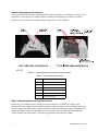
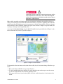
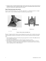
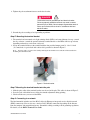
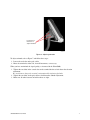
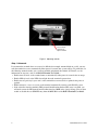
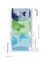
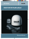
Installing the
Broadband Global Area Network (BGAN)
Fixed Mount Kit
Product description – BGAN fixed mount kit
Although the BGAN satellite modem terminal is designed for portable use, the BGAN Fixed Mount Kit
(HNS part number 3004066-0001) allows you to permanently mount the terminal if this option is desired.
The fixed mount kit (Figure 1) consists primarily of a tubular pole mount assembly with mounting brackets
on each end. The base bracket attaches to the roof or other structure and the terminal bracket attaches to the
BGAN terminal. Power and network cables are included.
This document describes how to install the BGAN Fixed Mount Kit. It references the BGAN Terminal
User Guide, which can be downloaded from the Hughes website at www.bgan.Hughes.com.
For your safety and protection, read this entire manual before you attempt to use the BGAN satellite
modem terminal. In particular, read the safety section at the end of this document carefully.
Figure 1: BGAN terminal with fixed mount
Step A. Inspecting the parts
Make sure you have all parts listed on the shipment box before beginning the installation; you should have
following parts:
•
•
•
•
•
•
•
•
•
Fixed Mount assembly
Tamper-proof hardware
Bits and tool to install camper-proof hardware
30 m extension power cable
Grounding cable
2 30 m Ethernet/ISDN cable
Level indicator
Compass
This instruction sheet, HNS 3004090-0001
The fasteners for securing the base bracket to the structure are not provided as part of the mounting kit.
Document number: 3004090-0001
Revision B.06 - November 16, 2009
Step B. Using tamper-proof fasteners
You can use the standard fastener hardware provided on the pole brackets or, for improved security of the
installation, you can replace the standard fasteners with the provided tamper proof fasteners (Table 1).
To replace the standard fasteners with the tamper-proof fasteners, refer to Figure 2.
Figure 2: Tamper proof terminal and base bracket fasteners
Table 1: List of tamper-proof fasteners
Item No.
Description
1
# 1/4-20 in. Penta nut
2
# 1/4-20 x 2.25 inch Penta screw
3
# 1/4-20 x 0.5 inch Penta screw
4
# 1/4-20 x 1.5 inch Penta screw
5
# 8-1/4 Penta plus bit
6
# 1/4 Penta socket
Step C. Determining where to install the terminal
In order for your terminal to work correctly, it must be installed in a location that provides a clear,
unobstructed, line of sight between the terminal and the satellite. Any objects such as building structures or
trees may degrade the quality of the satellite to terminal connection. To determine where to install the fixed
mount and terminal, you need to determine that you have both a clear unobstructed line of sight to the
satellite and that your fixed mount is aimed in the approximate direction to the satellite.
2
3004090-0001 Revision B.06
DANGER
A lightning strike on the terminal, mounting hardware or cabling
may cause death or serious injury and is likely to damage the
terminal. Do not employ an installation location which is likely to
experience a lightning strike.
Make suitable grounding and lightning protection arrangement to minimize the possibility of injury or
damage. Do not employ an installation location which is likely to experience a lightning strike and make
suitable grounding and lightning protection arrangements to minimize the possibility of injury or damage.
Professional local advice should be sought with respect to these matters. Hughes accepts no liability for
any injury or damage caused by lightning strikes.
An example of directional aiming using the BGAN LaunchPad tool is provided below in Figure 3 and a
full size worksheet for your use is provide in Figure 8.
Figure 3: Using the LaunchPad tool
To determine the direction from your location to the satellite, that is, directional aiming, follow the steps
below.
1. Refer to the Inmarsat BGAN coverage map in Figure 8.
2. Use the LaunchPad application and find your geographical location on the map or enter the nearest
city. In the example shown, the location is San Diego, USA.
3. The compass direction of your location (SSE 146o) to the satellite determines the orientation of the
mount.
3004090-0001 Revision B.06
3
4. Using the compass (provided), align the mount so that it points in the same compass direction that you
determined in step 3, above. If the line of sight is clear, that is, no obstructions, then you may use the
location to attach the now aligned mount to the structure.
Step D. Mounting the pole base bracket
You may install the fixed mount on any structurally sound surface, on a horizontal, vertical, or a sloped
surface, such as a roof or wall. Refer to Figure 4 and follow the procedures below.
Base bracket
Bubble level
G41540 C 10/09/09
Figure 4: Base bracket and bubble level
The pole is shipped attached to the base bracket. Mount the base bracket of this assembly to the structure
with the appropriate hardware (not included). Once the base bracket is mounted, perform the following
steps:
1. Insert the bubble level into the end of the pole (pipe) opposite the base bracket. The bubble level fits
into a shoulder inside the pole.
2. Loosen the pole attachment fasteners at the base bracket so the pole can swivel.
3. Swivel the pole until the end of the pole where the BGAN terminal will be installed is vertical (as
shown in Figure 1. Adjust the pipe position until the bubble is centered inside the circles on the top
surface of the bubble level as shown in Figure 4.
4
3004090-0001 Revision B.06
4. Tighten the pole attachment fasteners on the base bracket.
DANGER
The terminal must be grounded per local electrical codes.
Failure to properly ground the terminal may result in severe
personal injury or death. Do not attempt to ground the terminal
unless you have the skills to do so in accordance with local
electrical codes.
5. Ground the pole according to local grounding regulations.
Step E. Mounting the terminal bracket
1. The terminal can be mounted so its light-emitting diodes (LEDs) and control buttons face up—toward
the sky, or down— toward the ground. Orient the terminal bracket so the LEDs will face up or down,
depending on how they can be most easily read.
2. Secure the terminal bracket to the terminal with the four provided tamper proof ¼ - 20 x 1/2 inch
(12.5 mm) bolts. A special tool with a driver bit is provided as shown in Figure 5.
Note: You may want to to remove the stand by undoing the two thumb screws and take off the stand before
mounting the terminal bracket.
Figure 5: Terminal bracket
Step F. Mounting the terminal bracket onto the pole
1. Slide the pole collar of the terminal bracket over the end of the pole. This collar is shown in Figure 5.
2. Leave the pole collar bolts loose to allow for azimuth adjustment during pointing.
3. Check to make sure you can read the LEDs.
Step G. Connecting to a network
The fixed mount kit includes two 30 m RJ-45 cables for Ethernet or integrated services digital network
(ISDN) connectivity. You can also use a wireless LAN (WLAN) connection, depending on the distance
from the computer and potential interference. Ground the cabling according to local grounding regulations.
For details, see the BGAN Terminal User Guide.
3004090-0001 Revision B.06
5
Step H. Connecting power
1. Use the provided 30-m extension power cable between the terminal and the AC/DC adapter power
provided with the terminal. Connect the adapter to a power outlet. Ground the cabling according to
local grounding regulations.
2. If you install the terminal where temperatures may be extreme (less than -25 °C or greater than 60 °C),
remove the battery to prevent damage. The battery is needed only for portable use.
If you want to use power from a compatible solar panel, refer to the BGAN Terminal User Guide.
Step I. Pointing the BGAN terminal
DANGER
The terminal must be grounded per local electrical codes.
Failure to properly ground the terminal may result in severe
personal injury or death. Do not attempt to ground the terminal
unless you have the skills to do so in accordance with local
electrical codes.
The terminal includes an integrated antenna. For optimum performance, the terminal must be accurately
pointed at the satellite. The instructions in this section explain how to mechanically adjust the terminal’s
elevation angle and azimuth. These adjustments are required for pointing. To point the terminal, refer to
Figure 3 above and locate the appropriate Antenna Angle for your location. Figure 3 shows an angle of 47°
for our example location of San Diego. The terminal must be powered ON for pointing.
To adjust elevation, refer to Figure 6:
1. Loosen the two bolts in the curved slots on the terminal bracket.
2. Read the elevation angle from the elevation scale on the terminal bracket, using the red edge on the
pole collar as the angle indicator. View this edge through the curved slot on the terminal bracket.
3. Pivot the terminal on the pole to obtain the desired elevation angle.
6
3004090-0001 Revision B.06
Loosen these
fasteners to
adjust elevation
G41552 C
Figure 6: Adjusting elevation
To adjust azimuth, refer to Figure 7 and follow these steps:
1. Loosen the two bolts on the pole collar.
2. Move the terminal to either side, in small increments, as necessary.
When you have maximized the signal quality, as instructed in the User Guide:
1. Tighten the two bolts in the curved slots on the terminal bracket to lock down the elevation
adjustment.
Be careful not to change the terminal’s orientation while tightening the bolts.
2. Tighten the two bolts on the pole collar to lock down the azimuth adjustment.
3. Make sure all other fasteners on both brackets are tight.
3004090-0001 Revision B.06
7
G41553 C
Loosen these
fasteners to
adjust azimuth
Figure 7: Adjusting azimuth
Step J. Automode
If you mount the terminal where access may be difficult (for example, mounted high on a wall), you may
want the terminal to recover automatically when power is restored after a power outage. To permit this, set
the following automatic modes after you have installed and pointed the terminal. (For details, see the
information on automatic mode in the BGAN Terminal User Guide.)
• Enable Auto ON mode so the terminal turns on automatically when power is restored after an outage.
• Enable LED off mode so the LEDs do not light when the terminal is powered on.
• Enable Antenna pointing bypass mode so the terminal does not need to be re-pointed after power is
applied.
• Enable Automatic context activation so the terminal automatically connects to the BGAN system.
• If the subscriber interface module (SIM) personal identification number (PIN) entry is enabled, you
will need to enter the PIN from the man machine interface (MMI) after a power change. You can then
enable or disable the user SIM PIN entry from the MMI. Refer to the BGAN Terminal User Guide.
8
3004090-0001 Revision B.06
3004090-0001 Revision B.06
9
Figure 8: Directional aiming worksheet
Safety information
Read this safety section carefully. Keep this safety information where you can refer to it if necessary.
Warning symbols used in this manual
WARNING
Potential radio frequency (RF) hazard. Where you see this alert
symbol and WARNING, strictly follow the warning instructions to
avoid injury to eyes and other personal injury.
WARNING
Where you see this alert symbol and WARNING heading, strictly
follow the warning instructions to avoid personal injury.
DANGER
Electric Shock hazard: Where you see this alert symbol and
DANGER heading, strictly follow the warning instructions to
avoid electrical shock injury or death.
DANGER
A lightning strike on the terminal, mounting hardware or cabling
may cause death or serious injury and is likely to damage the
terminal. Do not employ an installation location which is likely to
experience a lightning strike.
Warnings for satellite terminals
Do not stand in front of the antenna
DANGER
This device emits radio frequency energy. To avoid injury, do not
place head or other body parts in front of the satellite antenna
when system is operational. Maintain a distance of two meters or
more from the front of the satellite terminal antenna.
Properly ground the terminal
DANGER
The terminal must be grounded per local electrical codes.
Failure to properly ground the terminal may result in severe
personal injury or death. Do not attempt to ground the terminal
unless you have the skills to do so in accordance with local
electrical codes.
Do not operate during electrical storms
DANGER
Operation of the satellite terminal during electrical storms may
result in severe personal injury or death. Disconnect the
computer from the terminal and remove the power to the
terminal until the storm is over.
3004090-0001 Revision B.06
11
General
WARNING
Handle your satellite terminal with care. The enclosure is
weather resistant per IEC 60529 IP55; however, do not
submerge the unit. Avoid exposing your satellite terminal to
extreme hot or cold temperatures out the range of -25 °C to
60 °C.
Avoid placing the terminal close to cigarettes, open flames or
any source of heat.
Changes or modifications to the terminal not expressly approved
by Hughes Network Systems could void your authority to
operate this equipment.
Only use a soft damp cloth to clean the terminal.
To avoid impaired terminal performance, please ensure the
unit’s antenna is not damaged or covered with foreign material
like pain or labeling.
When inserting the USIM/SIM. Do not bend or damage the
contacts in any way. When connecting the interface cables, do
not use excessive force.
In the vicinity of blasting work and in explosive environments
WARNING
Never use the satellite terminal where blasting work is in
progress. Observe all restrictions and follow any regulations or
rules. Areas with a potentially explosive environment are often,
but not always clearly marked. Do not use the terminal while at a
petrol filling station. Do not use near fuel or chemicals.
Copyright © 2005, 2009 Hughes Network Systems, LLC
All rights reserved. This publication and its contents are proprietary to Hughes Network Systems, LLC. No part of this publication may be reproduced in
any form or by any means without the written permission of Hughes Network Systems, LLC, 11717 Exploration Lane, Germantown, Maryland 20876.
Hughes Network Systems, LLC has made every effort to ensure the correctness and completeness of the material in this document. Hughes Network
Systems, LLC shall not be liable for errors contained herein. The information in this document is subject to change without notice. Hughes Network
Systems, LLC makes no warranty of any kind with regard to this material, including, but not limited to, the implied warranties of merchantability and
fitness for a particular purpose.
Trademarks
Hughes and Hughes Network Systems are trademarks of Hughes Network Systems, LLC. All other trademarks are the property of their respective
owners.
12
3004090-0001 Revision B.06
Qualified service
WARNING
Do not attempt to disassemble your satellite terminal. The unit
does not contain consumer-service components. Only qualified
service personnel may install or repair equipment.
Batteries and accessories
WARNING
Use approved batteries and accessories only. Use of nonapproved accessories may result in loss of performance,
damage to the satellite terminal, fire, electric shock or injury.
The AC power adapter is for indoor use only. It has an indoor
operating temperature range of 0 °C to +40 °C and provides an
output voltage of 20 VDC.
Connecting devices
WARNING
Never connect incompatible devices to the satellite terminal.
When connecting the satellite terminal to any other device, read
the device’s User manual for detailed safety instructions.
Pacemakers
DANGER
The various brands and models of cardiac pacemakers available
exhibit a wide range of immunity levels to radio signals.
Therefore, people who wear a cardiac pacemaker and who want
to use a Satellite Terminal should seek the advice of their
cardiologist. If, as a pacemaker user, you are still concerned
about interaction with the Satellite Terminal, we suggest you
follow these guidelines:
• Maintain a distance of 30 cm between the terminal and your
pacemaker.
• Maintain a distance of two meters from the front of the unit's
antenna.
• Refer to your pacemaker product literature for information
on your particular device.
If you have any reason to suspect that interference is taking
place, turn off your satellite terminal immediately!
3004090-0001 Revision B.06
13
Hearing Aids
DANGER
Most new models of hearing aids are immune to radio frequency
interference from Satellite Terminals that are more than 2 meters
away. Many types of older hearing aids may be susceptible to
interference, making it very difficult to use them near a Terminal.
Should interference be experienced, maintain additional
separation between you and the Satellite Terminal.
14
3004090-0001 Revision B.06