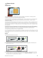
Download Hughes 9201 User Guide

Transcript
Hughes 9201 User Guide
P/N 3500152
Version 5.3
Copyright  2012 Hughes Network Systems, LLC.
All rights reserved. This publication and its contents are proprietary to Hughes Network Systems, LLC. No part
of this publication may be reproduced in any form or by any means without the written permission of
Hughes Network Systems, LLC., 11717 Exploration Lane, Germantown, Maryland 20876.
Hughes Network Systems, LLC., has made every effort to ensure the correctness and completeness of the
material in this document. Hughes Network Systems, LLC., shall not be liable for errors contained herein. The
information in this document is subject to change without notice. Hughes Network Systems, LLC. makes no
warranty of any kind with regard to this material, including, but not limited to, the implied warranties of
merchantability and fitness for a particular purpose.
Trademarks
All trademarks, marks, names, or product names referenced in this publication are the property of their
respective owners, and Hughes Network Systems, LLC. neither endorses nor otherwise sponsors any such
products or services referred to herein.
HUGHES and Hughes Network Systems are trademarks of Hughes Network Systems, LLC.
INMARSAT is a trademark of the International Mobile Satellite Organization. The Inmarsat LOGO and the
trademark BGAN are trademarks of Inmarsat (IP) Company Limited. All trademarks are licensed to
Inmarsat Limited.
SAFETY INFORMATION
For your safety and protection, read this entire user manual before you attempt to use the
Broadband Global Area Network (BGAN) Satellite Terminal. In particular, read this safety section
carefully. Keep this safety information where you can refer to it if necessary.
WARNING SYMBOLS USED IN THIS MANUAL
WARNING
Potential radio Frequency (RF) hazard. Where you see this alert symbol and
WARNING heading, strictly follow the warning instructions to avoid injury to
eyes or other personal injury.
WARNING
Where you see this alert symbol and WARNING heading, strictly follow the
warning instructions to avoid personal injury.
DANGER
Electric shock hazard: Where you see this alert symbol and DANGER heading,
strictly follow the warning instructions to avoid electric shock injury or death.
WARNINGS FOR SATELLITE TERMINAL
DO NOT STAND IN FRONT OF THE ANTENNA
This device emits radio frequency energy. To avoid injury, do not place head
or other body parts in front of the satellite antenna when system is operational.
Maintain a distance of two meters or more from the front of the Satellite
Terminal antenna.
PROPERLY GROUND THE EXTERNAL ANTENNA
Failure to properly ground the optional external antenna may result in severe
personal injury or death. Do not attempt to ground the optional external
antenna unless you have the skills to do so in accordance with local electrical
codes.
DO NOT OPERATE DURING ELECTRICAL STORMS
Operation of the Satellite Terminal during electrical storms may result in severe
personal injury or death. Disconnect the Terminal from the computer and store
the unit indoors if lightning is anticipated in the area of operation.
BGAN 9201 User Manual
i
GENERAL
Handle your Satellite Terminal with care. The enclosure is weather resistant per
IEC 60529 IP55; however, do not submerge the unit or expose it to severe rain
storms. Avoid exposing your Satellite Terminal to extreme hot or cold
temperatures outside the range -25ºC to +60ºC.
Avoid placing the Terminal close to cigarettes, open flames or any source of
heat.
Changes or modifications to the Terminal not expressly approved by Hughes
Network Systems could void your authority to operate this equipment.
Only use a soft damp cloth to clean the Terminal.
To avoid impaired Terminal performance, please ensure the unit’s antenna is
not damaged or covered with foreign material like paint or labeling.
When inserting the USIM/SIM, do not bend it or damage the contacts in any
way. When connecting the interface cables, do not use excessive force.
IN THE VICINITY OF BLASTING WORK AND IN EXPLOSIVE ENVIRONMENTS
Never use the Satellite Terminal where blasting work is in progress. Observe all
restrictions and follow any regulations or rules. Areas with a potentially
explosive environment are often, but not always, clearly marked. Do not use
the Terminal while at a petrol filling station. Do not use near fuel or chemicals.
QUALIFIED SERVICE
Do not attempt to disassemble your Satellite Terminal. The unit does not
contain consumer-serviceable components. Only qualified service personnel
may install or repair equipment.
BATTERIES AND ACCESSORIES
Use approved batteries and accessories only. Use of non-approved
accessories may result in loss of performance, damage to the Satellite
Terminal, fire, electric shock or injury.
The AC power adapter is for indoor use only. It has an indoor operating
temperature range of 0ºC to +40ºC and provides an output voltage of
19 VDC.
The storage capacity of the battery decreases when operated.
The terminal will only charge the battery when the temperature is within the
range of 0 to 45°C.
CONNECTING DEVICES
Never connect incompatible devices to the Satellite Terminal. When
connecting the Satellite Terminal to any other device, read the device’s User
Manual for detailed safety instructions.
ii
BGAN 9201 User Manual
PACEMAKERS
The various brands and models of cardiac pacemakers available exhibit a
wide range of immunity levels to radio signals. Therefore, people who wear a
cardiac pacemaker and who want to use a Satellite Terminal should seek the
advice of their cardiologist. If, as a pacemaker user, you are still concerned
about interaction with the Satellite Terminal, we suggest you follow these
guidelines:

Maintain a distance of 30 cm between the Terminal and your pacemaker;

Maintain a distance of two meters from the front of the unit’s antenna;

Refer to your pacemaker product literature for information on your
particular device.
If you have any reason to suspect that interference is taking place, turn off
your Satellite Terminal immediately!
HEARING AIDS
Most new models of hearing aids are immune to radio frequency interference
from Satellite Terminals that are more than 2 meters away. Many types of older
hearing aids may be susceptible to interference, making it very difficult to use
them near a Terminal. Should interference be experienced, maintain
additional separation between you and the Satellite Terminal.
BGAN 9201 User Manual
iii
CONTENTS
SAFETY INFORMATION _____________________________________________ I
Warning Symbols Used in this Manual...................................................... i
Warnings for Satellite Terminal ................................................................... i
CONTENTS ____________________________________________________ IV
INTRODUCTION _________________________________________________ 1
About This Product ...................................................................................... 1
About This User Guide ................................................................................ 2
Coverage Area ........................................................................................... 2
Package Contents ..................................................................................... 3
Minimum System Requirements ............................................................... 3
GETTING STARTED _______________________________________________ 4
Introduction to Getting Started ............................................................... 4
Setting Up Your Terminal ............................................................................ 4
Charging the Battery........................................................................... 6
Installing BGAN LaunchPad ...................................................................... 7
Obtaining a GPS Fix .................................................................................... 7
Connecting the Terminal to the Computer ........................................... 8
Connecting by USB .............................................................................. 9
Connecting by Ethernet ................................................................... 10
Connecting by ISDN .......................................................................... 11
Connecting by WLAN ....................................................................... 11
Connecting to the BGAN Network ....................................................... 12
Checking the GPS Status .................................................................. 12
Pointing the Terminal ................................................................................ 13
Terminal Stand Positioning ................................................................ 13
Using the BGAN LaunchPad Software ........................................... 15
Pointing Using the BGAN Terminal Signal quality LEDs ................ 16
Pointing Using the Audio Buzzer ...................................................... 16
Registering with the BGAN Network using the Web UI ...................... 17
Registering with the BGAN Network using LaunchPad ..................... 17
Registration status and coverage map ......................................... 17
Fixed/Semi-Fixed Installation ................................................................... 19
M2M Overview .......................................................................................... 19
M2M Satellite Terminal Point Once Installation Procedure ............... 20
Error cases............................................................................................ 21
TERMINAL OVERVIEW ___________________________________________ 23
Size and Weight ........................................................................................ 23
Terminal Interfaces ................................................................................... 23
iv
BGAN 9201 User Manual
Interface Overview and Defaults ................................................... 23
Establishing Communications Between a Computer And the UT24
Terminal Features ...................................................................................... 25
USIM/SIM Card .................................................................................... 25
Buttons .................................................................................................. 25
Indicator Lights (LEDs) ....................................................................... 26
Compass .............................................................................................. 28
Solar Panel Compatibility ................................................................. 28
Terminal Accessories ................................................................................ 29
DC Power Adapter ............................................................................ 29
Extended Battery ............................................................................... 29
AC Power Adapter ............................................................................ 30
Cables .................................................................................................. 30
Fixed Mount Kit ................................................................................... 30
External Antenna ............................................................................... 31
ISDN Compatible Devices ................................................................ 32
USING THE HUGHES UT WEB UI ____________________________________ 33
Accessing the UT Web UI ......................................................................... 33
Properties Page ......................................................................................... 34
Setup Page ................................................................................................ 36
Statistics Page ............................................................................................ 39
PDP Contexts Page .................................................................................. 40
WLAN ........................................................................................................... 43
WEP Security............................................................................................... 44
ACA ............................................................................................................. 45
ISDN ............................................................................................................. 47
SMS............................................................................................................... 49
M2M ............................................................................................................. 53
Features ...................................................................................................... 55
Security Management ............................................................................. 56
LAUNCHPAD SOFTWARE INSTALLATION ______________________________ 57
Supported Operating Systems ............................................................... 57
BGAN Launchpad Corporate Edition or Personal Edition ......... 57
Installation Wizard ..................................................................................... 58
BGAN LAUNCHPAD OVERVIEW___________________________________ 62
Launch Bar .......................................................................................... 62
Status bar ............................................................................................. 63
PIN Code entry .......................................................................................... 64
Personalization........................................................................................... 64
Pointing ....................................................................................................... 64
Main Display............................................................................................... 65
Multiple Users ............................................................................................. 65
BGAN 9201 User Manual
v
Connecting Terminal to PC and Other Devices Via WLAN Interface66
ISDN Equipment......................................................................................... 68
BGAN SERVICES ______________________________________________ 69
Voice Telephony Services ....................................................................... 69
Messaging Services .................................................................................. 70
Short Message Service (SMS) via BGAN LaunchPad .................. 70
Short Message Service (SMS) via Web UI ...................................... 70
Data Services ............................................................................................. 71
Default Connections ......................................................................... 71
Dedicated Streaming Connections ............................................... 71
VPNs ...................................................................................................... 72
ISDN Data ............................................................................................ 72
Opening Data Connections ............................................................ 72
Opening and Closing a Connection ............................................. 74
Opening a Dedicated Streaming Connection ........................... 75
Closing a Data Connection ............................................................. 75
Set up or Edit a VPN Connection .................................................... 76
Opening a VPN .................................................................................. 76
Closing a VPN ..................................................................................... 77
Adding or Editing a Dedicated Connection ...................................... 78
Setting Up an Icon ............................................................................. 78
Configuring Connection Quality..................................................... 79
Configuring Networking Parameters..................................................... 81
NAT vs Relay Mode ................................................................................... 83
Nat Mode ................................................................................................... 83
Relay Mode................................................................................................ 83
Managing ISDN Connections ................................................................. 84
Opening an ISDN Data Connection .............................................. 84
SERVICE FEATURES _____________________________________________ 85
Automatic Mode ...................................................................................... 85
Auto “On” Mode ................................................................................ 85
LED On/Off Mode .............................................................................. 85
Antenna Pointing Bypass .................................................................. 85
Automatic Context Activation ........................................................ 85
Front Panel LED Indicators for ACA ................................................ 86
LaunchPad “Automatic Connection Mode” Description ......... 86
USIM APN Mode vs. Manual APN Mode ........................................ 87
Phonebook................................................................................................. 88
Emergency Calls ....................................................................................... 88
PDP Contexts Overview ........................................................................... 89
PDP Contexts – Primary and Secondary ....................................... 89
IP Addressing ....................................................................................... 89
Multiple Users ............................................................................................. 90
vi
BGAN 9201 User Manual
Managing Contacts ................................................................................. 90
Adding and Editing Contacts.......................................................... 91
Exporting and Importing Contacts ................................................. 91
TCP PEP SOFTWARE ................................................................................... 93
Exit, Reset And Restart Features ............................................................. 94
Exiting LaunchPad ............................................................................. 94
Resetting the Terminal (Security code) .......................................... 94
Restarting the Terminal ..................................................................... 94
GETTING HELP ............................................................................................. 95
BGAN Profile Manager ............................................................................ 96
About Profile Manager ..................................................................... 96
Managing Profiles ............................................................................103
Security .....................................................................................................105
About Security and Control ...........................................................105
Changing the SIM PIN and Facility Password .............................105
Enabling a PIN...................................................................................106
Software Upgrade ..................................................................................107
Checking for Updates .....................................................................107
Software Versions and Availability ................................................107
Log Files .....................................................................................................109
Deleting or Clearing Log Files ........................................................109
Displaying Log Files ..........................................................................110
Emailing Log Files..............................................................................111
Printing Log Files ...............................................................................112
Saving Log Files to Disk ....................................................................113
Turning Logging On and Off ..........................................................113
POWER-ON SELF-TEST _________________________________________ 114
Satellite Terminal Boot Behavior ...........................................................114
SOFTWARE UPGRADER _________________________________________ 117
Instructions for the Hughes 9201 software upgrader .......................117
PIC Upgrade ............................................................................................121
MAC Upgrader ........................................................................................123
TROUBLE SHOOTING ___________________________________________ 124
TECHNOLOGY OVERVIEW _______________________________________ 127
GPS ............................................................................................................127
Obtaining a GPS Fix .........................................................................127
GPS and BGAN Registration ..........................................................127
ISDN ...........................................................................................................128
Dialing and Numbering ..................................................................128
PDP Context .............................................................................................128
WLAN .........................................................................................................129
Performance .....................................................................................129
BGAN 9201 User Manual
vii
SSID......................................................................................................129
TECHNICAL SPECIFICATIONS _____________________________________ 130
DECLARATION OF CONFORMITY __________________________________ 131
EU RoHS (Restriction of Hazardous Substances) Directive ..............131
EU WEEE (Waste Electrical and Electronic Equipment) Directives 131
GLOSSARY __________________________________________________ 132
viii
BGAN 9201 User Manual
INTRODUCTION
ABOUT THIS PRODUCT
The Hughes Network Systems (HNS) 9201 Broadband Satellite Terminal and WLAN Access Point is
your gateway to global communication. The 9201 allows you to simultaneously send and
receive IP packet and circuit-switched data via Universal Serial Bus (USB), Ethernet, Integrated
Services Digital Network (ISDN), and WLAN interfaces over the Inmarsat BGAN satellite network.
The 9201 unit offers you the following features and benefits:

492 Kbps data (transmit and receive)

Speech (4Kbps)

ISDN voice (3.1KHz audio)

ISDN data (64Kbps)

WLAN access point

Multi-user capability for sharing a single unit

Selectable Quality-of-Service (QoS)

Full IP compatibility for Email, file transfer (FTP), browsing, VPN, etc.

Cost-effective “always-on” access – charges only for data sent and received

UMTS IP-based services

WLAN, FCC, CE, and GMPCS certified

Subscriber Identification Module (SIM) card security

LED indicators and audio pointing aids for obtaining an Inmarsat satellite signal

GPS and WLAN status LEDs

Built-in battery for operation when AC power is not available.

Built-in antenna with look-angle and compass guides on the unit. Support for optional
external passive antenna.
The unit is easy to install and connects in minutes. It is built for use in fixed, semi-fixed, and
portable environments. The rugged design allows the unit to be installed outside in extreme
weather conditions for extended periods of time, and the small size and weight lets you easily
move it from site to site.
The Satellite Terminal carries a warranty for 12 months from the date of sale. Contact your
Service Provider if you have questions about the warranty, or need to return the terminal for
repair.
In this document, the following names and abbreviations are used to identify the Satellite
Terminal and your computer.
Term
Definition
ACA
Automatic Context Activation
Terminal
BGAN Satellite Terminal
UT
User Terminal; 9201 BGAN Satellite Terminal
TE
Terminal Equipment, e.g., a computer
BGAN 9201 User Manual
1
ABOUT THIS USER GUIDE
This user guide contains the most up-to-date information available on this product, on the date it
was written.
The following features only apply to release 3.8.1.0 and above:

Subscriber Phone Number

User Defined default APN

Sleep mode

Terminal Security.
COVERAGE AREA
The map shows the global coverage provided by the BGAN satellite network. You are able to
access one of the BGAN satellites by pointing the terminal to that satellite. In addition to the
satellites, the BGAN system includes infrastructure equipment on the ground that connects to
telephone networks and the internet. By accessing the satellites, your terminal can then connect
to telephone and data networks.
2
BGAN 9201 User Manual
PACKAGE CONTENTS
When you unpack the Satellite Terminal package, you will
find the following:

BGAN 9201 Broadband Satellite Terminal and WLAN
Access Point

Rechargeable lithium ion battery pack

AC power adapter and cable (100 – 240 VAC)

Travel adaptor

USB cable

Ethernet cable

ISDN cable
The following are available accessories not included in the package:

Extended lithium ion battery pack

Fix Mount Kit

DC (vehicular) power adapter

External passive antenna

2-4 wire ISDN terminal adapter
Your Service Provider will supply you with a Subscriber Identification Module (SIM) and its PIN,
and Satellite Terminal configuration instructions – you will need these to access the network.
Note: The SIM card will also have four (4) MSISDN numbers associated with it for the following
ISDN services:
4K Voice
3.1KHz Audio/Fax
64K UDI data
56K RDI data
MINIMUM SYSTEM REQUIREMENTS
These are the minimum computer system requirements for successful interface with the Satellite
Terminal:

Internet Browser: Microsoft Internet Explorer (7 or 8), Mozilla Firefox or Safari. Java must be
active and running version 1.6 or newer.

Support for at least one of these interfaces – USB, Ethernet, or WLAN (802.11b or b/g).

100 MB of free hard disk space (if using Inmarsat’s LaunchPad software).
BGAN 9201 User Manual
3
GETTING STARTED
INTRODUCTION TO GETTING STARTED
This section describes the simplest and quickest way to connect the 9201 Satellite UT to the
BGAN Network. If you are a first time user, you will be guided through the procedure for
powering up your terminal, obtaining a GPS fix, connecting your computer to the terminal, and
registering with the BGAN Network. You are then ready to start using voice and broadband
services.
SETTING UP YOUR TERMINAL
To set up your terminal, you must:

Install the USIM/SIM Card and the Battery supplied with your terminal

Charge the battery.
To set up the terminal:
1. Position the terminal so that the battery door is facing you.
2. Open the battery door. (If you have already installed the battery, release and then remove
it.)
3. Push the button on the left-hand side of the USIM/SIM card holder (use a retracted pen or
similar non-metallic object, if needed). This releases the SIM holder from its slot.
4
BGAN 9201 User Manual
4. Install the USIM/SIM card in the card holder, making sure it is snapped into place.
5. With the card in place, orient the holder with the card’s gold contacts facing down. Place
the holder back in its slot in the BGAN terminal.
6. Put the battery into its slot in the BGAN terminal and lock it in place. Close and lock the
battery door.
BGAN 9201 User Manual
5
CHARGING THE BATTERY
To charge the battery, connect the AC power adapter to the terminal and to an external power
source. The temperature of the battery must be within 0°C to 45°C for charging to take place
successfully.
USING THE AC POWER ADAPTER
The AC power adapter is for indoor use only. It has an indoor operating temperature range of
0ºC to 40ºC, and provides an output voltage of 19 VDC.
To power the terminal using the AC power adapter:
1. Remove the power adapter from the terminal box.
2. Insert the power adapter output connector to the DC Power Input Jack on the back of the
terminal, as shown below:
3. Plug the AC Power Cable into a suitable AC power outlet, and charge the battery for three
hours. If the AC Power cable does not fit into your power outlet, use the travel adapter.

You can operate the Satellite Terminal while the battery is charging.
Note
You are now ready to install the BGAN LaunchPad Software.
6
BGAN 9201 User Manual
INSTALLING BGAN LAUNCHPAD
As a first step, Inmarsat recommends that you install the BGAN LaunchPad Software on your
computer. You can use BGAN LaunchPad to open and manage data connections, manage
and monitor terminal operations, and monitor the status of the connections between your
terminal and your computer. Alternatively, you can use the Web-based User Interface (UI) built
into the UT by navigating your web browser to 192.168.128.100.
To install BGAN LaunchPad on your computer:
Download the latest LaunchPad from www.inmarsat.com/support
If you need more details, go to the section LaunchPad Software Installation on page 57.
When you start the BGAN LaunchPad application on your computer (TE) and connect to the
Terminal, the Terminal will query the current USIM/SIM card to see if the Personal Identification
Number (PIN) is enabled. If the PIN is enabled, the BGAN LaunchPad application displays a PIN
window and requires you to enter the correct SIM PIN. If the SIM PIN is disabled, then the BGAN
LaunchPad application bypasses this display. The correct PIN for your SIM should have been
supplied by your service provider when you received the USIM/SIM.
If SIM authentication was successful, you are now ready to obtain a GPS fix.
OBTAINING A GPS FIX
Your Satellite Terminal contains an integrated GPS receiver that is used to provide location
information to the BGAN network. GPS location information is required to register with the BGAN
network, and the terminal automatically tries to get a GPS every time it is powered on.
The GPS antenna is located in the main antenna. For optimum GPS signal reception, make sure
the Terminal is placed in a horizontal position pointed towards the sky. Since the GPS receiver
needs to see at least 3 satellites, it should have visibility of a large part of the sky without
obstructions from buildings, mountains or trees. To accomplish this, it might be necessary to take
your Satellite Terminal out to a clear space to obtain a new GPS location. It may be possible to
obtain a new GPS location in a less favorable circumstance, but the time to get the fix may be
longer.
Once the terminal gets a GPS fix, it stores the location, and the terminal can be moved to a
more convenient working area, such as inside a building by a window facing the BGAN satellite.
GENERAL INSTRUCTIONS
1. Take the Satellite Terminal outside and lay it down flat. Verify that the unit has an open view
of the sky to get a GPS fix.
2. Power up the Terminal. The GPS LED will start to flash green indicating the terminal is getting a
GPS fix.
3. Monitor either the BGAN LaunchPad GPS indicator or the Terminal’s GPS LED for the status of
the GPS fix. It may take a few minutes to get a fix. Once the terminal gets a GPS fix, the GPS
LED will turn solid green (then the LED will turn off once the UT registers with the BGAN
network).
The following describes the behavior of the GPS LED display as the terminal attempts to get a
GPS fix:
BGAN 9201 User Manual
7

Getting a fix: The LED flashing green indicates the terminal has not obtained a fix since it was
last powered on. The stored fix may be acceptable in which case the terminal may be able
to register, but the LED will continue to flash indicating the terminal is still trying to get a fix.

Needs a fix: The LED changes to flashing red indicating that the terminal tried to register, but
the GPS fix was rejected by the network. In this case, you may need to place the UT under
open sky and try again.

Got a fix: The LED changes to solid green when a new GPS fix is obtained. The LED will remain
on until the unit registers with the network and the fix is accepted. (Note that once the fix is
obtained, the GPS receiver will be turned off unless it is still downloading almanac data from
the GPS satellites).

Complete: The LED turns off when the unit successfully registers with the BGAN network.

GPS Failure: The LED will be solid red if the Terminal detects a hardware fault with the GPS
module.
You are now ready to Connect the Terminal to the Computer.
CONNECTING THE TERMINAL TO THE COMPUTER
You can connect devices to the BGAN terminal over any of the following interfaces:
 USB
 Ethernet
 Integrated Services Digital Network (ISDN)
 WLAN

Note

Note
There is no need to check the active interface. All interfaces can be used
simultaneously to accommodate multiple users.
During initial setup, the terminal can only be configured using either a USB or an
Ethernet connection. Once the terminal has been configured, all four interfaces
(USB, Ethernet, WLAN, and ISDN) can be used for data transfer depending on the
service required.
Your computer must be configured to support your chosen connection method.
Refer to the documentation supplied with your computer for details.
8
BGAN 9201 User Manual
CONNECTING BY USB
To connect the BGAN terminal to a computer using the USB port:
1. Connect the supplied USB cable to your computer’s USB port, and insert the other end of the
connector into the BGAN terminal’s USB port.
2. At the terminal, slide the cable through the rubber door slot in order to secure and protect
the connection.

Note
When plugging in the USB cable for the first time, you will see Windows installing a
new driver for the device.
USB drivers for the terminal are available from: www.inmarsat.com/support or
www.bgan.hughes.com.
When you plug the USB cable into your computer for the first time, your computer will detect
that new USB Hardware has been connected. You should then follow the computer’s
instruction to install the Hughes USB LAN LINK driver software (for computers using the
Windows operating system, the installation is carried out using a Found New Hardware
Wizard). Your computer will then use this driver to connect to the terminal.
BGAN 9201 User Manual
9
CONNECTING BY ETHERNET
To connect the BGAN terminal to a computer using Ethernet:
1. Connect the supplied Ethernet cable to your computer’s Ethernet port, and insert the other
end of the connector into the BGAN terminal’s Ethernet port.
2. At the terminal, slide the cable through the rubber door slot in order to secure and protect
the connection.
10
BGAN 9201 User Manual
CONNECTING BY ISDN
1. Connect the ISDN cable (use the provided Ethernet cable – it is a dual-use cable for both
Ethernet and ISDN) to your computer’s or phone’s ISDN port, and insert the other end of the
connector into the Terminal’s ISDN port.
2. At the Terminal, slide the cable through the rubber door slot in order to secure and protect
the connection.
CONNECTING BY WLAN
If you have not previously used the terminal’s WLAN interface, it has to be enabled from
LaunchPad or the terminal’s built-in Web UI, with your computer connected to the terminal using
either the USB or Ethernet interface. You can also enable the Wireless Encryption Protocol for
added security. When the terminal’s WLAN interface is enabled, the terminal’s WLAN LED is
either green (WEP is enabled) or red (WEP is not enabled).
Once configured, any computer with a WLAN interface can detect the terminal’s WLAN SSID,
and connect to it automatically.
Note: If WEP is enabled, you must provide other WLAN users with the proper WEP key in order for
them to connect to the terminal.
You are now ready to Register with the Network.
BGAN 9201 User Manual
11
CONNECTING TO THE BGAN NETWORK
Establishing a connection with the BGAN network requires the careful orientation of the BGAN
terminal towards the satellite, a process called pointing. Accurate and precise pointing is
important, because a badly-pointed antenna can reduce the data rate achievable over the
network. When pointing is complete, you can register the terminal onto the BGAN network
(registration is required before you can begin to use voice and data services over the BGAN
network).
CHECKING THE GPS STATUS
After you have connected your terminal to a computer, you can check the GPS status by
opening the BGAN LaunchPad application. Refer to the BGAN LaunchPad status bar and the
GPS indicator light on your BGAN terminal for the current GPS status. The table below indicates
each possible status:
LaunchPad Status
bar symbol
Terminal GPS indicator
light
Flashing Green
Solid Green
Off
Flashing Red
Solid Red
12
Status
The terminal is getting a GPS fix after being
turned on. If you have not changed location
since last registering, you may be able to reregister with your last valid fix. Otherwise, you
must wait until a new fix has been obtained
(and the antenna is properly pointed) before
registration can successfully occur.
The terminal has a valid GPS fix. You are ready
to point the terminal and register.
The terminal has successfully registered.
The network will not allow you to register with
the stored GPS fix. You need to get a new GPS
fix.
The GPS receiver in the terminal is faulty.
Contact your Service Provider.
BGAN 9201 User Manual
POINTING THE TERMINAL
You can use the BGAN terminal signal quality indicator lights for pointing if you know the
approximate direction to the BGAN satellite.
TERMINAL STAND POSITIONING
The terminal’s stand is used to position the terminal in the correct orientation.
1. Place the Satellite Terminal on a flat surface. Find the knobs located on each side of the unit.
Loosen the knobs by rotating them both towards the unit, in the direction shown.
2. To prepare to lift the Terminal, place a finger in the lower right-hand corner of the unit and
place your other hand in the middle of the unit.
3. Pull out the front stabilizer. Lay the Terminal back on the flat surface.
4. Lift up the Terminal while referring to the protractor on the right-hand side. The protractor
gives you the angle at which the unit is positioned. Note that an angle of 0 to 45 degrees is
displayed on the inside portion of the protractor, while an angle of 46 to 90 degrees is
displayed on the outside portion. To start, select an angle between 15 and 30 degrees.
BGAN 9201 User Manual
13
5. After you have positioned the Terminal at the desired angle, tighten the knobs by turning
them away from the unit. Tighten them so that they are firm and hold the angle but are still
movable in case further adjustments are needed. Note that both knobs will gradually tighten
if you push the unit to a lower angle. This can help with locking the unit when the desired
protractor angle is close to 90 degrees.
6. You can use the built-in compass for pointing the terminal in the correct direction. Refer to
the Antenna Pointing section for further instructions.
Do not stand in front of the Antenna
The Satellite Terminal emits radio frequency energy when in operation. Do not
stand or place objects in front of the antenna while the terminal is operational.
Warning
14
BGAN 9201 User Manual
USING THE BGAN LAUNCHPAD SOFTWARE
Start the BGAN LaunchPad application on your computer. The Setup Screen is shown below in
Pointing Mode.
1. Confirm your nearest city in the information box to the left of the map. You can change it by
clicking on the map at your current location or click on nearest city and then select from the
list. Your location will be used to determine the recommended antenna angle and compass
direction to any visible satellites. LaunchPad gives the compass direction in both degrees
and direction (the compass shows direction as North, South, East and West, with 10 degree
divisions).
2. Correctly point the terminal using one of the methods described below.
3. When you are ready to register with the network, click on Register with Network now. Refer to
Registering with the BGAN Network.
Note: You can also register with the network by pressing the “Audio” button on the terminal
for 3-4 seconds. Alternatively, if you have an ISDN handset connected to the terminal, you
can exit pointing and register by pressing the #1# keys.
Once the GPS light goes out on the terminal, the terminal is registered with the network.
4. When you have successfully registered with the network, your position will be displayed on
the map, but only if allowed by local regulations.
5. You can now make phone calls or set up data connections as described later.
BGAN 9201 User Manual
15
POINTING USING THE BGAN TERMINAL SIGNAL QUALITY LEDS
To point the antenna using the LEDs:
1. Set the angle and position of the BGAN terminal using the compass and the graduated
scale. If you do not know the angle and position to set the terminal to, use the BGAN
LaunchPad pointing screen for guidance.
Watch the behavior of the Pointing Indicator LEDs as you point the terminal in order to obtain
the maximum possible signal quality. Remember, the better the job you do pointing the
terminal, the better the quality of the data and voice connections you will be able to make
with it later.
2. The following table shows the colors of the pointing LEDs from the weakest to strongest, as
you point the terminal to the BGAN satellite:
3. When you have finished pointing the terminal, you are ready to register with the network. Go
to the next section Registering with the BGAN Network.
POINTING USING THE AUDIO BUZZER
You can also monitor the signal quality during pointing by using the terminal’s built-in audio
buzzer. By default the audio buzzer is switched off. To use the buzzer when the terminal is in
pointing mode:
1. Press the audio button to turn the buzzer on.
2. Monitor the signal quality using the buzzer. The higher the pitch and the shorter the interval
between tones, the stronger the signal.
16
BGAN 9201 User Manual
3. When you have finished pointing the terminal, you are ready to register with the network.
Go to the next section, Registering with the BGAN Network, for registering with LaunchPad or
the terminal’s built-in Web UI.
Note: You can also register with the network by pressing the “Audio” button on the terminal
for 3-4 seconds. Once the GPS light goes out, the terminal is registered with the network and
you can start to make ISDN calls without the use of LaunchPad.
4. When you register with the network, the buzzer turns off automatically.
Note: If the audio button is pressed when the unit is not in pointing mode, it will have no
effect.

Note
The audio buzzer will always default to off when the unit powers on. When the unit
is in pointing mode, pressing the Audio button (located in the front of the terminal)
turns the buzzer on. Pressing it again turns the buzzer off. A long press of the button
(3-4 seconds) starts registration with the BGAN network. Once you exit pointing,
the buzzer will turn off. If the Audio button is pressed when the unit is not in pointing
mode, it will have no effect.
REGISTERING WITH THE BGAN NETWORK USING THE WEB UI
When you have successfully pointed the antenna, you then need to exit antenna pointing and
register with the BGAN network. You can do this from the Properties page of the terminal’s builtin Web UI. See page 34 for details.
REGISTERING WITH THE BGAN NETWORK USING LAUNCHPAD
When you have successfully pointed the antenna, you then need to exit antenna pointing and
register with the network. You can do this by a long press of the audio button located on the
terminal. Alternatively, if you have an ISDN handset connected to the terminal, you can exit
pointing and register by pressing the #1# keys. Otherwise, you can click on the Register with
network now button on the BGAN LaunchPad pointing window.
REGISTRATION STATUS AND COVERAGE MAP
This page appears when you first start the LaunchPad application. It displays the registration
date and time, terminal location information, other registration information, and the expected
satellite coverage zone.
Note: The map depicts the BGAN network's expectations of coverage, but does not represent a
guarantee of service. The availability of service at the edge of coverage areas fluctuates
depending on various conditions.
BGAN 9201 User Manual
17
18
BGAN 9201 User Manual
FIXED/SEMI-FIXED INSTALLATION
The satellite terminal can be mounted on a pole or flat surface (such as a wall or roof) using the
Fixed Mount Kit accessory. This kit includes all the installation brackets, mounting hardware, tools,
and instructions to complete the installation, except for the screws, bolts, etc. required to mount
it to the structure. Proper installation ensures that the terminal is always correctly pointed at the
satellite. Once properly mounted, the terminal can then be left alone for an extended period of
time without having to be re-pointed or set-up. The Fixed Mount Kit accessory can also be reused to install the terminal in different locations.
When mounted in a location where access to the terminal may not be straightforward (for
example, mounted high on a wall), you may want the terminal to recover automatically after a
power outage. To permit this, the following automatic mode settings are recommended (see
the Automatic Mode section on page 85 for more details):

Auto on mode is enabled

LED off mode is enabled

Antenna pointing bypass is enabled or Point Once mode is selected

Automatic context activation (ACA) is enabled or an Always On context is configured (see
the M2M Web page)

SIM PIN entry is disabled
In addition, it is recommended that the battery be removed to prevent it from being damaged
at extreme temperatures.
M2M OVERVIEW
The 9201 BGAN Terminal can be used unattended in a Machine-to-Machine (M2M) scenario,
e.g., for SCADA applications. For this scenario, the terminal should be configured as described
below. Note that the parameters described below are only supported on the terminal’s Web UI
(i.e., they are not accessible using the LaunchPad application).
SETUP Page:
Bypass Antenna Pointing – Point Once (or On)
Auto Power On: On
This allows the unit to come back on line automatically after a power cycle.
M2M Page
If you need the terminal maintain a PDP context at all times, use the Context Watchdog option:
1. Configure one or more IP addresses that can be pinged by the UT over the satellite link.
For example, use DNS server IP addresses.
Note that at least one address must be provided if this feature is enabled, but setting two
or three addresses may help if there is difficulty reaching the first address.
2. Set the time between watchdog pings in order to control the interval at which the UT will
check the link. Note that the minimum allowed value is 5 minutes.
To have the terminal automatically set up a context on power up, use the Always On Context
feature:
1. If you only require a single “always on” context, set the Always On Context parameter on
the M2M web page to On. If you require multiple contexts, use the options on the ACA
page instead.
BGAN 9201 User Manual
19
2. Set the Always on Static ACA IP Address if the desired TE has a known static IP address or
if it never sends ARPs to the terminal. Alternatively, you can leave this IP address field
blank (0.0.0.0), and the UT will set up a context for the first device it detects through ARP
during startup.
With the Always On ACA feature enabled, the UT will set up the desired PDP context at startup,
and automatically reactivate it if it is ever deactivated.
SMS Remote Control
To control the 9201 unit remotely, use the Remote SMS Control feature – see the Features (page
55) and SMS Remote Settings (page 52) web pages for details.
M2M SATELLITE TERMINAL POINT ONCE INSTALLATION PROCEDURE
Use the following procedure to install an M2M 9201 satellite terminal with the Point Once option
(Setup Web UI page). This procedure assumes the 9201 terminal is mounted in the optional
NEMA 4X enclosure shown below, but the same basic procedure can be used without the
enclosure.
1. Prepare the M2M satellite terminal: route power and Ethernet cables through the cable
ports, mount the 9201 in the enclosure, and connect all cables. Set the housing to the
correct elevation angle for your location (at 0 degrees, the unit is vertical, pointing to the
horizon, and at 90 degrees, it is horizontal, pointing to the sky).
2. Mount the unit so that the satellite terminal has a clear view of the satellite. Connect
power to the terminal.
3. The satellite terminal will power up and within a few seconds will enter pointing mode
and generate audible pointing tones (if in “Point Once” mode already). During staging
the unit must be configured for “Point Once”. Note that when in Point Once mode, the
audio pointing tones will occur automatically, without having to press the audio button.
4. Standing to the side, behind, or below the terminal so as not to block the signal, rotate it
to maximize the signal – the audio tones will increase in pitch and frequency as the signal
improves.
20
BGAN 9201 User Manual
5. Once the direction has been optimized, rotate the elevation to maximize the signal. This
may be unnecessary if the unit was previously set to the correct elevation angle.
6. The signal may also be checked by viewing the reflection of the pointing LEDs on the
inside top surface of the enclosure. Ideally at least 4 green LEDs should be visible. (This
represents a C/No value of 54dB).
7. When the signal has been maximized, tighten the mounting screws.
8. Press the audio button on the top of the unit (you may have to tilt it out of the housing to
get access to the button). The pointing tones and pointing LEDs will turn off.
9. Close the lid and insert and tighten the 4 screws that hold the lid closed. Apply a
padlock to the latch if required.
10. Two minutes after the audio button is pressed, the unit will start to transmit and register
with the network: it will start a “registering” audio tone (high pitched beep, beep which
repeats after a 2 second silence). Note that this tone will be muffled because the box is
sealed. From this point forward, the installer should avoid putting their body within 1
meter of the front of the satellite terminal due to RF fields.
11. Once the terminal registers and attaches to the network, the “registering” tone will turn
off (after about 10 seconds).
12. The unit will then activate a data connection to the network (if an “Always On” context is
configured on the M2M Web UI page). While the connection is being activated, a
“connecting” tone will be heard (2 pairs of high/low beeps which repeat after 2 seconds
of silence). If the unit connects quickly, this tone may not be heard at all.
13. Once the data connection is active, the “connecting” tone will turn off (after 5 to 10
seconds) and the “installation complete tune” will play (low to high scale, 3 times). The
unit is now fully functional.
14. The installer should now verify correct operation/end-to-end connectivity between the
user equipment and the BGAN network before leaving the site.
Once the Point Once install process completes successfully, the satellite terminal will set a flag in
its non-volatile memory. The unit will use this flag to bypass the pointing operation and tone
generation on subsequent power ups (for example, if the unit reboots or power is lost and then
restored).
If any problem is encountered during the installation process, the installer can (long) press the
terminal’s power button at any time. This will power down the unit and delete the pointing
complete flag. As a result of this, on the next power up, the unit will re-enter the pointing process
(see Step 3 above).
ERROR CASES
Pointing tones not heard on power up when trying to install
Unit may have been previously pointed: power down with the power button and power up
again.
Alternatively, the wrong terminal software may be installed, or the point once configuration
option may not be set – you can check these on the terminal’s Properties and Setup web pages.
Registering tone does not turn off
The unit may be incorrectly pointed and the signal may be too weak – check pointing
procedure.
The SIM may be inactive and may be rejected – check with the satellite service provider.
Connecting tone does not turn off
The unit may be incorrectly pointed and the signal may be too weak – check pointing
procedure.
BGAN 9201 User Manual
21
The SIM subscription may be wrong – check with the satellite service provider.
Connecting tone does not turn on
Always on data connection may not be configured (check M2M web page).
22
BGAN 9201 User Manual
TERMINAL OVERVIEW
SIZE AND WEIGHT
The 9201 Satellite User Terminal (UT) is 27.5 cm x 34.5 cm x 5.0 cm. Its weight is 2.8 kg (including
the battery).
The small size and weight allow you to easily move it from site to site, and it can be connected
at a new site in minutes.
TERMINAL INTERFACES
INTERFACE OVERVIEW AND DEFAULTS
The 9201 Satellite Terminal includes four interfaces that can connect to your computer.

Ethernet

USB

ISDN (for voice and data)

WLAN (IEEE 802.11b)
By default, the ISDN, USB, and Ethernet interfaces are active when the unit is turned on. The
802.11b Wireless LAN (WLAN) interface is disabled by factory default, but it can be enabled by
using the BGAN LaunchPad application software or the terminal’s built-in Web UI.
When the Terminal is connected to a DC power source, such as an AC adapter, the ISDN
interface remains on at all times. Conversely, when running only from the battery, the ISDN
interface will turn off 5 minutes after pointing is completed if no ISDN device is connected. You
can re-enable the ISDN interface from the BGAN LaunchPad or Web UI if you subsequently need
to connect an ISDN device. This saves power and maximizes operating times because the ISDN
power sourcing circuitry uses power even if no device is connected. If an ISDN device is
connected at power up and then disconnected before the 5 minute timer expires, the ISDN
interface will power off.
The following table summarizes the interface on/off behavior during battery and AC Power
operation:
Interface
Battery Operation
AC Power Operation
USB
On
On
Ethernet
On
On
ISDN
On.
On
After 5 minutes, if no ISDN
device is detected, turns off
WLAN
Off
(default)
Off
Off
Enabled
On
On
BGAN 9201 User Manual
23
ESTABLISHING COMMUNICATIONS BETWEEN A COMPUTER AND THE UT
ETHERNET
Ethernet communications are established by connecting your computer Ethernet LAN port
directly to the Satellite Terminal LAN port via the supplied Ethernet cable.
USB
USB communications are established by connecting your computer USB port directly to the
Satellite Terminal USB port via the supplied USB cable. Please ensure that you have the proper
USB driver installed on the computer before connecting the cable for the first time.
ISDN
ISDN communications are established by connecting your computer ISDN port or ISDN device
directly to the Satellite Terminal ISDN port via the supplied ISDN cable (same as the Ethernet
cable).
With the ISDN interface, you can make voice or data calls. Only one terminal at a time may
make a call, since only one B channel is supported per Terminal in the BGAN system. However,
up to four ISDN phones may be utilized with the terminal’s single ISDN connection by using a
passive ISDN splitter. Note that only one of the ISDN devices may make a call at one time.
WLAN
The WLAN function is used in access point mode. You can use the BGAN LaunchPad or Web UI
to configure the following parameters:

Wireless LAN interface on/off. The default is off.

Network (SSID) name. The default is “BGAN”, but you can change it.

Channel number. This controls the radio channel number (1-14) used by the access point.
Depending on your country, only certain subsets of these channels may be used (3 options:
France, Spain, or Rest of the World). Channel 11 is common to almost all countries, so it is
used as the default.

Encryption. 64- or 128-bit WEP encryption can be enabled. Up to 4 WEP keys can be
entered, in either Hexadecimal or ASCII format.
Note: Not all computer Operating Systems will convert ASCII to hexadecimal when setting up
a WLAN connection. If you have any problems, please use the hexadecimal WEP key to
connect your computer to the terminal.
Up to a total of eleven users can access the Satellite Terminal simultaneously through the
Ethernet, USB, and WLAN interfaces. For example, a hub or router may be connected to the
terminal’s Ethernet port, thereby allowing multiple computers to have access (note that if a hub
is used, each computer can have its own PDP Context, but if a router is used, then all connected
computers must share one PDP Context).
24
BGAN 9201 User Manual
TERMINAL FEATURES
USIM/SIM CARD
The USIM card contains an identity that uniquely identifies a subscriber. The USIM provides
storage for subscription and subscriber-related information.
Access to the USIM, and therefore to the BGAN system, can be restricted to an authorized user
or number of users, using the USIM Personal Identification Number (PIN). The PIN is stored
securely in the USIM.
The USIM personalization feature ensures that access to a terminal or other user equipment can
be restricted to an authorized USIM. The USIM and the terminal share a code stored securely in
the USIM and the terminal. If a USIM fails to prove its knowledge of the code, it is denied access
to the terminal.
If the USIM is removed during operation, the terminal will deactivate any active PDP contexts,
detach from the network, and enter a "NO SIM" operational mode. If the USIM is reinserted while
the terminal is still powered on, it must be restarted (use the terminal’s power button to
accomplish this) to detect the new or replaced USIM.
If you change the SIM card, you may need to reconfigure the terminal’s ACA settings, e.g., if the
APN or username/password are different between the two SIM cards, as this information is stored
in each SIM.
BUTTONS
The Satellite Terminal has two buttons:

The Power button is used for turning the terminal on or off. A long press of the button will
either turn it on or off.

The Audio button is used for switching the audio tones on and off. These tones occur only
while the terminal is in pointing mode (see the section Using the Audio Buzzer on page 16).
Press the button to turn the tones on and off.
BGAN 9201 User Manual
25
Once you have the terminal correctly pointed to the satellite, you can long press (3-4
seconds) the Audio button to register with the network. You can tell when you are registered
with the network when the solid green GPS LED goes out.

INDICATOR LIGHTS (LEDS)
The terminal LEDs indicate the status of the Satellite Terminal. The figures below illustrate where
the LEDs are located on the terminal and the function of each.
POWER LED
The Power LED indicates power status:
LED
Status
Off
Terminal is turned off
Green
Flashing Red
Flashing Green
Terminal is powered on
Fault detected
Operating on battery power, or the power button has been
pressed and the terminal is powering down.
BATTERY LED
The Battery LED indicates the battery status and functions differently depending on whether the
terminal is powered from an external power adapter or from the internal battery:
LED
While on External Power: Status
Off
No battery
Green
Flashing Green
26
Battery fully charged
Battery charging
BGAN 9201 User Manual
Flashing Red
Battery Fault – not charging
LED
While on Internal Battery: Status
Off
Unit is off
Green
Flashing Green
Terminal on, in pointing mode
Terminal on, pointing completed
Flashing Red
(fast)
Terminal on, battery low (Power LED is green)
Flashing Red
(slow)
Terminal on, battery fault detected (Power LED is also flashing
red)
POINTING LEDS
These six, two-color LEDs are used during power-up, Antenna Pointing, and ACA (Automatic
Context activation (see ACA Section on page 45 for details).
When the terminal is powered on, the power LED turns green. As the Satellite Terminal progresses
through the power-on self tests, each of the 6 pointing LEDs turn green or red/green in turn, and
then turn off if the terminal successfully completed power-on self-test. See the Power-On Self
Test section on page 114 for full details.
These LEDs also indicate the signal quality during antenna pointing - see the Antenna Pointing
section on page 16 for details).
WIRELESS LAN LED

This LED is green if the terminal’s Wireless LAN is on and Wireless Encryption Protocol (WEP) is
enabled.

This LED is red if the Wireless LAN is on and WEP is disabled.
BGAN 9201 User Manual
27

If the Wireless LAN is enabled and the terminal is operating on battery power alone, this LED
flashes to save power after the unit exits pointing.
GPS LED
The GPS unit in the Satellite Terminal will attempt to get a GPS fix each time the unit powers up.
The GPS LED indicates the state of the GPS fix - see the Obtaining a GPS Fix section on page 7 for
details.
COMPASS
Use the compass during the Antenna Pointing process to point the terminal in the direction of
the satellite. The BGAN LaunchPad software can be used to determine the correct direction.
North is 0 degrees, East is 90 degrees, South is 180 degrees, and West is 270 degrees, with each
division on the compass corresponding to 10 degrees.

Note
The compass accuracy can be affected if the terminal is placed close to
magnetic fields or ferromagnetic materials.
SOLAR PANEL COMPATIBILITY
The terminal is compatible with several solar panels. The easiest way to interface to a solar
panel is through the supplied DC Power Adapter. The output of the DC power adapter is
plugged into the terminal, with the input (cigarette lighter adapter) connected to the output of
the solar panel.
The terminal has been tested to work with the following solar panels:

IDG T-60 (3 panels) form IDG Europe (60W max, 3.3A at max power)

SunCatcher F0001 (2 panels) from Powerline Electronics Accessories (14.5W max)

55 Watt Solar West Panel
28
BGAN 9201 User Manual
TERMINAL ACCESSORIES
Terminal accessories include:

DC Power Adapter

Extended Battery

AC Power Adapter

Cables

Compatible Devices

Fixed Installation Kit
Each is described in this section.
DC POWER ADAPTER
The DC power adapter can be purchased through your distributor or supplier. It has an
operating temperature range of -25ºC to +55ºC, and provides an output voltage of 20VDC. It
can be used with input voltages in the range 10 to 32VDC.
EXTENDED BATTERY
The Extended lithium ion battery pack can be purchased through your distributor or supplier.
The Extended battery pack has the same form factor as the standard battery pack, with 50%
more capacity.
BGAN 9201 User Manual
29
AC POWER ADAPTER
The AC power adapter is for indoor use only. It has an indoor operating temperature range of
0ºC to +40ºC, and provides an output voltage of 19VDC.
When the Satellite Terminal is first connected to AC power, the unit powers on automatically.
Note that the Terminal will still charge the battery if it is turned off.
CABLES
The Satellite Terminal package comes with a USB cable and cables that provide Ethernet and
ISDN connectivity.

USB cable

Ethernet/ISDN 10 meter cable
When the Terminal is connected directly to a PC, it uses a regular Ethernet cable (shown above).
If the Terminal is connected directly to a hub or router, a "crossover" LAN cable may be required.
FIXED MOUNT KIT
The following items are found in the Fixed Mount Kit. The user is responsible for mounting the
hardware to a suitable surface.

30
Fixed Mount Screws (anti-theft)
BGAN 9201 User Manual

30 meter Cord for AC Power Adaptor
This allows the AC Main power adaptor to be located up to 30 meters away from the
terminal.

Ethernet/ISDN 30 meter cable
EXTERNAL ANTENNA

The external antenna is a 20” x 20” x .5” (500mm x 500mm x 12mm) passive antenna with a
10 meter long cable. It can be mounted permanently using the Fixed Mount Kit accessory.
BGAN 9201 User Manual
31
ISDN COMPATIBLE DEVICES
The 9201 Satellite terminal has been successfully tested with the following ISDN handsets:

ASCOM Eurit 33 plus

SwissVoice Eurit 25

Nera and Thrane ISDN handsets

Siemens Gigaset SX255

Hughes 2-4 Wire terminal adapter using any 2-wire analog handset
32
BGAN 9201 User Manual
USING THE HUGHES UT WEB UI
ACCESSING THE UT WEB UI
The Hughes 9201 Satellite Terminal (UT) includes its own internal Web User Interface (UI). To
access the UT Web UI, open a Web Browser and type in the internal IP address of the UT, i.e.,
http://192.168.128.100.
The Web UI is supported on Internet Explorer (7 and 8), Firefox, and Safari. The Status Display
shown in the top left corner of the web pages requires Java V1.6 or newer. Note that Firefox
and Safari sometimes add a space or a strange character in blank fields. These need to be
deleted when configuring a password or username, e.g. on the PDP contexts or ACA pages.
The Web UI works better with IE8 if “Compatibility Mode” is selected on the browser.
The web UI opens up to the “Properties” page as shown below:
BGAN 9201 User Manual
33
PROPERTIES PAGE
The Properties page shows the current status of the UT. A description of each item on the page
follows:
In the Top left-hand corner of the screen you will notice the following Status Display items:
Satellite Signal Strength (C/No), Beam ID, Battery/Power status, and Wireless LAN status. These
items are updated automatically when the status of any of these items changes.
Below the Status Display is a column of links to the other UT web UI pages (all of them will be
described in the following pages). This part of the web page is common to all web pages, and
provides for navigation between pages.
The main (center) part of the page shows:
1. Registration Status: This field indicates whether you are Registered with the Network. To
register, click on the “Register with Network” button. Once the registration process
begins or is complete, the button will be grayed-out, as shown above.
2. PS Attach Status: This indicates whether you are PS (Packet Switch) attached to the
Network. Once PS Attached (and assuming no ACA or Always On functions are
enabled), you will then need to setup a PDP Context in order to send PS data.
3. CS Attach Status: This indicates whether you are CS (Circuit Switch) attached to the
Network. Once you are CS Attached and Registered with the network, you are able to
make CS calls.
4. GPS Position: This field displays the current GPS position status. If you have received a
GPS fix and the Network GPS policy has been received (and it allows the GPS position to
be shown to the user), it will display the Latitude, Longitude, Fix Quality, and the Last time
the GPS position was updated. Time displayed is GMT time.
5. Emergency Call Numbers: This field displays the Emergency call numbers that can be
used with the UT.
34
BGAN 9201 User Manual
6. Software Version: This displays the current version of software that is running on the UT.
7. Alarms: This displays any current alarms that have been detected by the terminal.
8. Satellite Modem IMEI: This displays the IMEI number of the UT.
9. Satellite Modem IMSI: This displays the IMSI number of the USIM card in the UT. If the IMSI
is not displayed, it indicates that there is a problem reading the SIM card, e.g., because
there is no SIM, it is installed incorrectly, or the SIM PIN must be entered.
10. USIM PIN Status: This field indicates whether the USIM is ready or the PIN has to be
entered. If the PIN needs to be entered, go to the SETUP page.
11. USIM APN Name: This displays the APN that has been programmed on the USIM card.
Note that some USIM cards may have multiple APNs provisioned.
12. Subscriber Phone Number: The subscriber number (MS-ISDN 1) is shown here if it has
been programmed into the USIM.
13. Extract System Log: Clicking this button allows the User to automatically extract a UT
system log and save the file to a location on the TE for debugging purposes. This file can
be e-mailed to Hughes directly for fault analysis if the User experiences any problems.
Note: if you encounter problems downloading the file, check the firewall and other
settings on your PC, such as McAfee Host Intrusion Prevention, as these can sometimes
block FTP.
14. Restore Factory Defaults: Clicking this button will restore the UT back to factory defaults
and delete any of the User parameters that have been set-up in the UT. Hughes highly
recommends that the User exhaust all possible debug procedures before using this
feature.
BGAN 9201 User Manual
35
SETUP PAGE
The Setup page allows the User to configure various parameters of the UT. Many of the
parameters on this page require a restart of the terminal to take effect. A description of each
item on the page follows:
1. Terminal Local IP Address: This allows the User to change the local IP address of the
terminal from the default 192.168.128.100 IP address. All four octets can be changed.
Once the local IP address is changed on this page and applied, the IP address ranges
for the DHCP server, the PDP Context page, the ACA page, and the M2M page will also
be changed automatically. Note: Updates to this field will not take effect until the UT is
restarted.
When changing the IP Address, be sure to make a note of the new address, as you will
need it to access the UT. (Refer to Trouble Shooting page 124 if you forget the address.)
After restarting the UT to change the IP address, disconnect and reconnect the TE to allow
it to clear and update its IP configuration. You must then enter the new IP address of the
UT in the browser to re-access the web UI.
2. Terminal Subnet Mask: This allows the User to change the UT subnet mask. For example,
if you wish to use a Class B address on the UT, set the subnet mask to 255.255.0.0. Note:
Updates to this field will not take effect until the UT is restarted.
Note: This subnet mask will also be used in Relay mode once the context is activated,
rather than setting it based on the class of IP address assigned to the context.
36
BGAN 9201 User Manual
3. DHCP Server: This allows the User to enable or disable the UT’s on-board DHCP server.
Note: Updates to this field will not take effect until the UT is restarted.
4. DHCP Address Range: This allows the User to set the range of DHCP addresses that are
given out by the UT to any connected TE/DHCP client. Note: Updates to this field will not
take effect until the UT is restarted.
5. Idle Mode DHCP Lease Time: The Idle Mode DHCP Lease Time refers to the DHCP lease
time used when the UT is not connected to the BGAN network. This parameter allows the
User to change the default time (60 seconds) that the DHCP lease to the TE is good for.
This parameter was introduced because of a problem with some models of Cisco routers
that would not accept a short DHCP lease time. Note: The longer the idle mode DHCP
lease time, the longer it will take the Network/UT to update the TE with the correct DNS
servers for web browsing after establishing a PDP context. Updates to this field will not
take effect until the UT is restarted.
6. Connected Mode DHCP Lease Time: The Connected Mode DHCP Lease Time refers to
the DHCP lease time used when the UT is connected to the network. Most Users will
have no need to change this parameter. Note: Updates to this field will not take effect
until the UT is restarted. Also note the value of the Connected Mode DHCP Lease Time is
automatically changed if the User changes the Netmode to Relay Mode (this is done in
order to better operate while deactivating a PDP Context while in Relay Mode).
7. PIN and PUK: The PIN and PUK fields indicate whether the PIN or PUK needs to be
entered to unlock the terminal. When grayed out, they indicate the field is not required
or it has already been satisfied.
8. Bypass Antenna Pointing: This parameter allows the User to bypass the antenna pointing
procedure at startup and have the UT go straight into Registering with the Network. Point
Once is another form of pointing bypass and is described in the M2M Satellite Terminal
Point Once Installation Procedure section on page 20.
9. Auto Power On: This parameter is set when the User wants the UT to power up
automatically when AC/DC power is applied to the UT (instead of having to press the
power button).
10. Terminal Indicator LEDs: Determines whether the indicator LEDs on the terminal are on or
off by default. Typically this should be set to on, but if the unit is installed outdoors you
may want to turn off the LEDs to make the unit less noticeable.
11. 24/7 PDP Keep Alive: If this option is enabled, the UT will automatically request another
PDP context if the current PDP context is torn down due to inactivity. This is an older-style
capability of the terminal: the Always On PDP context with keep alive (configured on the
M2M web page) may be a better option. Note: The 24/7 function should not be
enabled unless you need to keep the PDP context alive for critical information. Enabling
this function is not a good use of satellite resources. Updates to this field will not take
effect until the UT is restarted.
12. Netmode: This field indicates the mode of operation of the terminal. In NAT mode the UT
will translate between the local and global IP addresses. In Relay mode the UT will supply
the global IP address to the TE once a PDP Context is established. Relay mode is single
user/single PDP Context and only supports a single connected TE (see NAT vs Relay Mode
section on page 83 for details). Note: Updates to this field will not take effect until the UT
is restarted.
13. Sleep Mode: If enabled, the UT will use sleep mode when idle on the regional beam. This
reduces idle mode power consumption and can increase battery standby time. A
reboot is required as this parameter must be set at startup for it to take effect.
14. Streaming Inactivity Timer: When enabled, this allows the terminal to utilize a timer that
can detect inactivity for a Streaming QoS that has been setup.
15. Streaming Inactivity Timeout: When the Streaming Inactivity Timer function is enabled,
the value of the timeout denotes how much streaming inactive time (in seconds) must
elapse before the UT automatically tears down the streaming context.
BGAN 9201 User Manual
37
16. Emergency Call Numbers: Allows the User to update the emergency call numbers that
are applicable in the part of the world where the terminal is being used.
17. User defined Default APN: This field can be used to define a default APN that is used
(instead of the APN in the USIM) for:
a. the default APN on the PDP Contexts page
b. the APN fields on the ACA page for undefined ACA entries
c. the APN for Dynamic ACA
d. the APN field on the M2M page if the Always On context is Off. If the Always On
context is active, you must manually change the APN on the M2M Page.
18. Default APN Username and Password: Define the username and/or password for the
default APN if required.
19. Apply, Cancel, and Restart Terminal buttons: These buttons are self-explanatory. Once
any desired change has been made to a field on this page, click the Apply button. As
mentioned earlier, a restart of the terminal may be required for the applied change(s) to
take effect.
38
BGAN 9201 User Manual
STATISTICS PAGE
The Statistics web page provides an estimate of the amount of Packet Switched data sent and
received on background PDP Contexts, the time elapsed for streaming contexts, and the time
elapsed for CS calls. The data is broken up into the following types:
Trip: The trip counter is similar to the trip counter on your vehicle. It can be zeroed out at any
time by the User, and it will track the statistics until the User resets it.
Lifetime: The Lifetime counter is similar to the odometer on your vehicle. It shows the statistics of
the terminal since the software version that added this feature was loaded onto the UT. The User
cannot reset these counters.
CS Statistics: The CS statistics relate to calls placed by/received by the terminal. These also
include the time of the latest call.
Note: If the UT power is abruptly disconnected for some reason, the UT will not be able to
save the statistics to flash and hence the statistics for the session may be inaccurate.
BGAN 9201 User Manual
39
PDP CONTEXTS PAGE
The PDP Contexts page allows the User to setup and configure PDP Contexts for any TE that is
connected (or even not connected yet) to the UT. To activate a PDP Context, go to the bottom
of the page. You will see the CID (Context ID), Local IP Address, Requested QoS, APN,
Username, and Password fields:
1. CID: The CID (Context ID) of each context is automatic by default. If for some
reason the User wants to assign a particular context to a specific CID, use the drop
down arrow and select the desired CID number. Most users will not need to change
this field from the automatic/default setting.
2. Local IP: This is the local IP address of the TE that you want to setup the PDP Context
for. The TE IP address is automatically filled in based on the IP Address of the
computer currently connected to the Web UI. Note that the first three octets of the
IP address will reflect any changes made (on the Setup web page) to the UT local IP
address.
You can use the “ipconfig” command from a “cmd” (DOS prompt) window on your
PC computer to find the IP address of your computer (note: this will also give you the
“Gateway” IP address of the UT (assuming “Obtain an IP Address Automatically” is set
for the computer’s network connection to the terminal)). To determine the
computer’s IP address on a Mac, for Mac OS X, under the Apple Menu go to "System
Preferences" -> “Network” and Show “Built-in Ethernet” or “Airport”. The IP address is
under TCP/IP. Alternatively, go to "About this Mac" -> "More Info" -> "Network" and
select “Built-in Ethernet” or "Airport".
3. QoS: The drop down list shows all of the different QoS types supported: Background,
32K, 64K, 128K, 176K, 256K, and X-Stream. Select the appropriate QoS required for
the PDP context that you are setting up. Note that the look-angle (elevation setting
once properly pointed) of the terminal may limit your ability to successfully use higher
QoS rates.
4. APN name: This field is configurable, but by default it shows the User Defined APN
entered on the Setup page, or if that is not defined, it shows the APN read from the
USIM. If you have a USIM that has been provisioned with multiple APNs, you can type
in any of these other APN names here, if desired.
40
BGAN 9201 User Manual
5. Username (UN)/Password (PW): Some Service Providers require a Username and
Password to be used when setting up a PDP Context (this is often required when using
Static Global IP addresses assigned by the Service provider). Provide those values
here.
Activating a PDP Context:
To activate a PDP context, perform the following:
Do not modify the CID field unless you need to setup a specific ID for one of your devices.
Leaving it blank will allow the software to automatically choose the next CID that is available.
Next, enter the local IP address of the device that you want to setup the connection for.
Next, select the QoS that is needed by selecting it from the drop down list.
The APN is read from the USIM card and is usually not changed unless you have more than one
APN provisioned on the USIM card.
If your Service Provider requires a username or password, enter it in the Username and Password
boxes, then click on “Create Context”.
The new connection will show up in the connection table (see screen shot below for example).
Note: In Relay Mode you can only have one context, and it must be configured to use CID 1.
Background Context activated for 192.168.128.101
Once the context has been setup, whether it is successful or not, the context field/row in the
table will always be populated until you click on the “Clear” box. This allows you to be able to
retry/re-activate using the existing context parameters (see CID #1 below).
You can tell if a context is active by looking to see if the Global IP Address and DNS fields are
populated on the context’s row in the table. If they are populated, the context is active.
BGAN 9201 User Manual
41
PDP Contexts Page Example: CID #1 Inactive; CID #2 Active
Activating Multiple PDP Contexts
To activate multiple PDP contexts for additional TE devices, follow the same procedures above.
Each time you activate a context for a particular local IP address, it will show up in the table
similar to the screen shot below.
42
BGAN 9201 User Manual
WLAN
The Wireless LAN web page allows the User to enable, disable, and configure the Wireless LAN
functionality of the terminal. Note that Wireless LAN Security is controlled on a different web
page.
Connecting by WLAN
If you have not previously used the terminal’s WLAN interface, it has to first be enabled from the
web UI with a computer connected to the terminal using a wired (Ethernet or USB) interface.
Once enabled/configured, TEs can connect to the terminal wirelessly.
Fields on this page include:

WLAN Power: Turns the Wireless LAN interface on/off. The default is off (disabled).

SSID: Network (SSID) name. The default is “BGAN”, but you can change it to whatever you
want. Note that you can “hide” the SSID on the WEP Security page.

Region: This defines the geographical region in which you are operating the UT. Based on
your selection, the Channel choices in the “Channel” parameter will be restricted.

Channel: WLAN Channel number. This controls the radio channel number (1-14) used by the
access point. Depending on the country you are in, only certain subsets of these channels
may be used (7 options: FCC (USA), IC (Canada), ETSI (most of Europe), Spain, France, and 2
options for Japan). Channel 11 is common to almost all countries, so it is used as the default.
Note that if performance issues occur over the WLAN interface, changing the Channel may
help.
BGAN 9201 User Manual
43
WEP SECURITY
The Wireless LAN Security page allows the User to configure WEP for use when the terminal is
communicating wirelessly to TEs. Note that WEP is the only form of wireless encryption supported.
Fields on this page include:

WEP Protection Status: Select “On” from the drop down list to enable the Wireless Encryption
Protocol (WEP) for added security. When the terminal’s WLAN interface is enabled, the
WLAN LED is either green (WEP is enabled) or red (WEP is not enabled). When the LED is red,
any computer with a WLAN interface can detect the terminal’s WLAN SSID, and connect to
it automatically. Therefore, it is recommended that WEP Security be configured/enabled.

Encryption Level: 64- or 128-bit WEP Encryption can be enabled. To switch from one level of
encryption to another, click the button in the upper-right corner of the page.

WEP Key 1: Default WEP keys are formulated using the IMEI number of the terminal. If you
want to use different WEP keys, please use the following table as a reference when entering
the new WEP keys:
o Hexadecimal 128-bit: Requires 26 characters. Recommended
o Hexadecimal 64-bit: Requires 10 characters
(When using 64-bit WEP Encryption, additional WEP Keys appear on the page)
Note: If WEP is enabled, you must provide other WLAN users with the proper WEP key in order
for them to connect to the terminal wirelessly.
SSID Broadcast: For added security, you can choose to not broadcast the terminal’s WLAN
SSID. Note: this feature does not work with older 9201 units equipped with the Agere Wireless
LAN card. These units are marked MCN 3003920-0001).

44
MAC Filtering: For added security, click on ENABLE from the drop down list and then you can
define up to 10 selected MAC addresses that are allowed to connect to your WLAN.
Note: To find out the MAC address of a PC, go to a DOS prompt and type “ipconfig /all”.
For Mac OS X, under the Apple Menu go to "System Preferences" -> “Network” and Show
“Airport”. The “Airport Id” is the MAC address. Alternatively, go to "About this Mac" -> "More
Info" -> "Network" and select "Airport".
BGAN 9201 User Manual
ACA
Automatic Context Activation, or ACA, is a function where the 9201 terminal can detect the
presence of TE(s) at startup, and based on configuration set on the ACA web page, the terminal
can automatically create and activate PDP Context(s) as specified (no manual creation is
needed on the PDP Contexts web page in this case). In addition, the context(s) can be
configured to activate only upon the presence of data from each TE.
The ACA web page allows you to configure the Automatic Context Activation function based
on two different kinds of TE IP connections to the terminal:
1. If using a static IP address on the TE, you can establish an automatic (ACA) PDP context
with any QoS that is offered by the network (refer to the upper half of the ACA web
page).
2. If using DHCP on the TE (“Obtain an IP Address Automatically”), you can establish an
automatic ACA background PDP context for any TE that connects to the UT via DHCP
(refer to the lower part of the ACA web page). Note that streaming QoSs are not
supported when ACA is used for DHCP clients (hence the function is referred to Dynamic
Background ACA on the web page).
In either case, you can also choose whether the context should be activated as soon as the UT
detects the device (“on” or “off” in the web page settings), or if the context should only be
activated when the TE attempts to send data over the satellite link (“DA” in the web page
settings, which stands for “data activated”). Note that with Data Activated contexts, if the
context is ever deactivated, it will automatically be reactivated when more data is sent.
The UT must be restarted before it will automatically activate contexts for newly-configured ACA
entries.
Note: If you change the SIM card, you may need to reconfigure your ACA settings, e.g., if the
APN or username or password is different between the two SIM cards.
Fields on this page include:

ACA Settings for TEs with Static IP Addresses: You can define your own range of static IP
addresses for setting up an automatic ACA PDP context with any of the QoSs offered by the
network. In this way, when a TE connects to the terminal using any IP address in the range, a
PDP Context for it will be setup using the QoS specified.
To turn on a particular range of addresses, select the “On” radio button and choose a range
of addresses (low and high) to use (e.g., 192.168.128.200 to 192.168.128.209), or leave the
defaults. To have the context only be activated when the TE sends data, select “DA”
instead of “On”.
Next, select the desired QoS for that range of IP addresses (32K streaming, 64K streaming,
etc).
The APN listed is the default APN defined on the Setup page or the APN read from the USIM
card. If your USIM is provisioned for more than one APN, then you can enter a different APN
in this field.
If your Service Provider requires a username and password, enter them in the next two fields.
If you want to setup additional ranges of addresses, follow the same instructions as above.
Note: You cannot overlap the IP address ranges. If you do, an error will pop-up telling you
that you have an overlap region. Check all of the ranges for overlaps and try again.
When you are finished, click on “Apply” and you should see a message saying “Operation
Successful”. A restart is needed for the changes to take effect.
BGAN 9201 User Manual
45

ACA Settings for TEs Using DHCP Assigned IP Addresses: This option allows you to set up the
UT for Dynamic Background ACA. This means that any device configured to connect to the
terminal via DHCP will automatically receive a background PDP context.
The APN is the User Defined APN entered on the Setup page, or if that is not defined, it shows
the APN read from the USIM.
To activate this feature, select the “On” radio button and click on “Apply”. To have the
context only be activated when the TE sends data, select “DA” instead of “On”.
To see if the ACA context(s) have been setup properly, restart the terminal and ensure the TE(s)
desired for ACA operation are connected to the terminal. Next, click on the PDP Contexts web
page, and it will show you all the contexts that have been setup (active or inactive). See the
screen shot below as an example.
46
BGAN 9201 User Manual
ISDN
You can establish ISDN data communication by connecting your ISDN equipment directly to the
BGAN Terminal’s ISDN port with the supplied ISDN cable (which is the same as the Ethernet
cable). This web page allows you to activate 40V power sourcing on the ISDN interface, and set
MSN numbering options.
1. ISDN Power Sourcing: To turn on the ISDN power sourcing click on the “On” radio button.
The ISDN device should receive 40V power immediately via the ISDN cable. This field
should be on unless you never use ISDN or are using an ISDN device that has its own
power source.
2. MSN Speech: By default, MSN 1 is entered into the MSN Speech number text box. To
receive incoming calls, you must program the same MSN into your ISDN handset
connected to the ISDN port.
3. MSN 3.1 KHz audio: By default, MSN 2 is entered into the MSN 3.1 KHz Audio number text
box. To receive incoming calls, you must program the same MSN into your ISDN fax
machine connected to the ISDN port.
4. MSN UDI (Unrestricted Digital Information): By default, MSN 3 is entered into the MSN UDI
text box. UDI is a 64 Kbps service that is a European standard ISDN data service.
5. MSN RDI (Restricted Digital Information): By default, MSN 3 is entered into the MSN RDI
text box. RDI is a 56 Kbps service that is normally found in the USA.
6. Trigger for Mobile-Originated call type (Bearer): This box controls the mechanism used
by the terminal to select the bearer type for mobile originated calls. By default, “Bearer
capability” is set as the trigger in this text box. There is also an option under the drop
down arrow to set the trigger to use the MSN rather than the bearer. Most ISDN devices
correctly signal the call type (speech, 3.1KHz audio, UDI, RDI) via the bearer capability. If
there is a problem, this field can be changed to use the MSN number instead.
BGAN 9201 User Manual
47
Once all changes have been made, click on “Apply”. Any changes to this screen require a reboot of the terminal to save the new configuration. Use the power button on the UT or the
“Restart Terminal” button to gracefully power down and power back up the UT.
Note: You can use different MSNs for any of the ISDN call types above, but your ISDN equipment
must be programmed with the same MSN to accept incoming calls, and you must use different
numbers for speech, audio and UDI/RDI calls.
48
BGAN 9201 User Manual
SMS
You can manage SMS text messages from the SMS pages which provide a similar function to
LaunchPad. You must have a valid Service Center number configured in order to send
messages – see the SMS Settings Page.
On the Inbox page you can view your received messages. If there are more than 10 messages,
you can view the older ones by changing the page number and pressing Go. You can also
reply to messages or forward them.
You may need to periodically delete messages to prevent the SIM from filling up which will
prevent the receipt of new messages. You can select a single message and press the “Delete”
button, or use the “Delete All” button which deletes all received, sent and draft SMS messages.
After entering a message you can save it to drafts rather than sending it by pressing the “Save”
button.
BGAN 9201 User Manual
49
The Sent page allows you to view previously sent messages. Again, you may need to periodically
delete messages to prevent the SIM from filling up.
The Drafts page allows you to view previously saved messages. After editing a message you can
resave (Update) or send the message.
50
BGAN 9201 User Manual
On the Compose page you can write new messages. After entering a message you can save it
to drafts or send it.
On the Settings page you can configure the default settings for messages. You must have a
valid Service Center number configured in order to send messages.
BGAN 9201 User Manual
51
On the Remote Settings page you can enable the unit to receive and act on special remote
control SMS messages. Contact your service provider for more information on this feature. Before
this feature can be enabled you must obtain the feature activation code from your service
provider and activate the feature from the Features Web page.
You can configure the password that must be contained in remote control SMS messages. Be
sure to make a note of the password if you change it from the default. Note: If you activate this
feature and do not change the password, it is possible that other people may be able to send
control messages to your unit.
If the Enhanced Security feature is active, the Password field will be blank to hide the password.
Remote control messages will be deleted after they are received and will not be stored in the
SIM.
52
BGAN 9201 User Manual
M2M
The M2M page allows you to configure features specially designed for unattended units, e.g.
units used for Machine to Machine applications such as SCADA.
Context Watchdog: If you need the unit to maintain a PDP context at all times, use the Context
Watchdog feature.

Context Watchdog To detect problems and auto recover, set this field to On.

Configure one or more Ping IP addresses that can be pinged by the UT over the satellite
link. For example, use DNS server IP addresses.
Note that at least one address must be provided if this feature is enabled, but setting
two or three addresses may help if there is difficulty reaching the first address.

Time between pings. Set this parameter to control the interval at which the UT will check
the link. The minimum value is 5 minutes.

If the Ping Required field is set, the UT will always send the pings at the ping interval. If the
field is not set, the UT will not send pings if data was successfully sent within half the ping
interval. This setting reduces the number of pings sent over the air.
BGAN 9201 User Manual
53
Always On Context: To have the unit automatically set up a context on power up, set Always
on Context to On. The UT will set up the context at startup and reactivate it if it is ever
deactivated.

If the TE has a known static IP address or never ARPs, enter this address. Alternatively,
leave the IP address blank (0.0.0.0) and the UT will set up a context for the first device it
detects through ARP during startup.

The QoS should be left as Background. Setting a steam QoS should only be used in
exceptional circumstances where a stream is required the whole time the unit is powered
on.

APN will be filled in with the user defined default APN from the Setup page, or, if that is
not defined, the APN read from the SIM. It can be changed if necessary.

Fill in the Username and Password if required for context activation.
If you change the SIM card you may need to reconfigure your Always On Context settings, e.g. if
the APN or username or password is different between the two SIM cards.
For static units that are installed once, the Point Once option on the Setup page is
recommended.
To control the unit remotely, use the SMS Remote Control feature – see the Features page and
SMS Remote settings.
54
BGAN 9201 User Manual
FEATURES
You can enable special features from this page. Before features can be used you must obtain
the feature activation code from your service provider and activate the feature by entering the
UT specific code in the Feature Activation Code field. You will need to provide the unit IMEI to
the Service Provider. This can be found on the Properties Page.
SMS Remote Management allows the unit to receive and act on special remote control SMS
messages. To use the feature you must next enable it on the Remote Settings SMS page.
Enhanced Security allows you to lock the UT so that it can only be accessed locally after
entering a password. Refer to the Security Management section below. When this feature is
active, the remote SMS password will be stored encrypted and will not be visible on the Remote
Settings SMS page.
BGAN 9201 User Manual
55
SECURITY MANAGEMENT
For added security, e.g. for unattended units, you can lock the UT so that it cannot be accessed
locally. This is controlled by a security password configured from the Security Management page
accessible from the Feature Management page.
When the feature is active, each time the UT starts up, the password must be entered before the
user interface can be accessed. All local IP ports are blocked, e.g. so AT commands,
LaunchPad and the upgrader cannot be used. User data can be sent if a PDP context is up
which could be activated by ACA.
To activate the security feature, select “Password Protection” On, enter the same password
string in both fields and press “Apply”. If the two password fields match, the password is saved
and security is enabled.
The UT will be locked when it restarts, or to immediately lock it, press “Lock Unit”
Make a note of the password as it cannot be viewed and once the UT is locked it cannot be
accessed.
To deactivate the security feature, select “Password Protection” Off and press “Apply”.
If the Web UI is accessed when the UT is locked, the browser is redirected to the Login page and
the password must be entered. If the wrong password is entered three times in a row, password
entry is locked out and the UT must be restarted before the password will be accepted.
56
BGAN 9201 User Manual
LAUNCHPAD SOFTWARE INSTALLATION
SUPPORTED OPERATING SYSTEMS
LaunchPad supports the following Laptop/PC operating systems:

Microsoft Windows® 7, Vista, XP and 2000

Mac OS X (Intel and non Intel hardware)

Note
You must disconnect any existing LAN connections on your PC before proceeding with
installation. This avoids any conflict with the network configuration that you are setting
up for the Satellite Terminal.
You must verify that the proxy server settings in your browser are disabled. For Microsoft
Internet Explorer, select Tools / Internet Options / Connections / LAN Settings and
uncheck the box labeled “Use a proxy server for your LAN.” For Netscape, go to
Advanced Preferences and select “Direct connection to the Internet.” When
complete please close your browser. DO NOT FORGET TO RECHECK THIS BOX ON
RETURN TO YOUR OTHER INTERNET CONNECTION.
BGAN LAUNCHPAD CORPORATE EDITION OR PERSONAL EDITION
You can install either the Personal Edition or the Corporate Edition.
BGAN LaunchPad Personal Edition is designed for personal use:

All BGAN LaunchPad features are available

You can personalize all of BGAN LaunchPad's functions and features without restriction.
BGAN LaunchPad Corporate Edition is for corporate users:

A user profile is required with the corporate edition. A user profile is created with a separate
application called BGAN LaunchPad Corporate Profile Maker.

The user profile defines user restrictions so some features may not be available to you,
depending on the configuration that has been set up by your Corporate IT Manager or
service provider.

You are asked to enter a username and password when logging in to BGAN LaunchPad.
BGAN 9201 User Manual
57
INSTALLATION WIZARD
Run the LaunchPad Installation Wizard.
The following steps show the installation process:
7. The Installer prepares to install the LaunchPad software. It asks you accept the licensing
agreement.
8. Follow the on-screen instructions. Note the following recommended choices:
 Make sure you select the appropriate Edition (Corporate or Personal) when prompted.
58
BGAN 9201 User Manual
 Special Corporate Edition Instruction:

Inmarsat recommends that you install BGAN LaunchPad Profile Manager with the
Corporate Edition. If you want to install Profile Manager, select Browse CD for any
extra features, and follow the on-screen instructions.
9. Select the directory into which LaunchPad will be installed.
BGAN 9201 User Manual
59
Other items for selection and installation messages:
 Shortcut Destination Selection
 Pre-Installation Summary
60
BGAN 9201 User Manual
 Installation Complete
PLEASE NOTE that the BGAN LaunchPad version numbers shown in these examples will most likely
be different than the versions numbers you will see when you perform the installation.
BGAN 9201 User Manual
61
BGAN LAUNCHPAD OVERVIEW
The BGAN User Interface is called BGAN LaunchPad, and allows you to view and manage the
terminal’s operations and status via a user-friendly set of tools installed on your computer.
This is the screen that is displayed when you first start LaunchPad.
BGAN LaunchPad contains the following:
LAUNCH BAR
While in the LaunchPad application, you can click on any of the following icons to display the
associated page of information, where you can perform BGAN LaunchPad functions:
62
BGAN 9201 User Manual
The launch bar options include:

Data connections  Use for connecting to the Internet to browse Web sites and send and
receive emails. This section also includes advanced functions such as video and FTP
configuration.

Phone options  Provides a phonebook (only for use with SMS).

Text message options  Use for sending and receiving text messages.

Usage information  Shows circuit switched and packet switched usage information.

Services information  Lists Service Provider support options.

Support information  Provides LaunchPad help and Service Provider contact details.
STATUS BAR
The Connected to status, terminal Status and Signal strength are all shown on the status bar at
the bottom of the page, as shown below:
BGAN 9201 User Manual
63
PIN CODE ENTRY
When the BGAN LaunchPad is started and connects to the Satellite Terminal, the terminal
queries the current SIM card to see if the SIM PIN is enabled. If the SIM PIN is enabled, the BGAN
LaunchPad displays a SIM PIN window and asks for a valid SIM PIN before service is enabled.
If the SIM PIN is disabled then the BGAN LaunchPad will bypass this display.
PERSONALIZATION
After the PIN check, if Personalization is enabled and any checks fail, the BGAN LaunchPad
displays the Security window and asks you to enter a valid de-personalization code. If all
Personalization checks pass, the terminal will bypass the Security window. If personalization is
enabled, the de-personalization code should have been supplied with the USIM/SIM.
POINTING
After the PIN and Personalization checks, the pointing screen is displayed. Once you have
completed pointing, click the Register with Network Now button to exit pointing and connect to
the network.
See the section on Pointing the Terminal: Using the BGAN LaunchPad for details on how to use
the Pointing Screen.
64
BGAN 9201 User Manual
MAIN DISPLAY
Once all the initial checks have been completed, and the user presses the Register button, the
main BGAN LaunchPad page is displayed, showing progress towards acquiring the network.
MULTIPLE USERS
Up to 11 users attached to the Ethernet, USB and Wireless LAN interfaces can access the BGAN
LaunchPad at the same time.
In a multi-user scenario, each user must establish their own PDP context with the network, either
using LaunchPad or the ACA feature.
BGAN 9201 User Manual
65
CONNECTING TERMINAL TO PC AND OTHER DEVICES VIA WLAN INTERFACE
The terminal provides WLAN access to any computer which has a WLAN interface.
The terminal’s WLAN interface is configurable via the BGAN LaunchPad, as follows:
1. From the BGAN LaunchPad main menu, select Terminal > WLAN Interface Settings. The
Configure WLAN Interface dialog box is then displayed:
2. Select Enable to activate the WLAN interface.
3. Enter a Network Name (SSID). The default is BGAN, but you can change this if required.
4. Select a Region from the drop-down list (France, Spain, or The rest of the World).
5. Select a Channel number from the drop-down list. This controls the channel number (1-14)
used by the access point. Depending on the country only certain options are available for
selection. Channel 11 is common to almost all regulatory options, and so is the default.
6. Select a WEP Key Length from the drop-down list. There are two key lengths available, 64 bit
and 128 bit. 128 bit offers a higher level of security, but may cause a slight decrease in
performance.
7. Select a WEP Key Format at the Enter WEP key in: text box. This can be either Hex or ASCII.
Hex keys use hexadecimal numbers (0-9, A-F) to encrypt and decrypt data, and are the
most widely supported format. Plain text (ASCII) keys are supported on some operating
systems (check that your operating system supports ASCII before you select this option).
8. Enter up to four WEP Keys. The format depends on whether you selected Hex or ASCII.
 Hex – Enter a two digit hexadecimal number (0-9, A-F) in each box on the WEP Key 1 row.
You can enter up to four keys in total, and you should change the default key periodically
for added security.
66
BGAN 9201 User Manual
 ASCII – Enter a string of 5 characters for 64 bit encryption, or 13 characters for 128 bit
encryption. You can enter up to four keys in total, and you should change the default key
periodically for added security. Note: Not all operating systems can convert ASCII to
hexadecimal format. If you have problems connecting via WLAN using an ASCII WEP key,
try using the hexadecimal WEP key instead.
Note: Check that each key that you set up here is exactly the same as each key on your
computer’s WLAN interface; i.e. WEP Key 1 on the LaunchPad must be the same as Key 1
on the computer WLAN interface, and so on.
9. Click OK to save the changes, Cancel to exit without saving, or Apply to apply the settings
for this WLAN session only.
The following table summarizes the default settings.
Parameter
Description
Default
Wireless access
Turn on/off
WLAN
Interface
Disabled
Network Name
(SSID)
Sets the SSID
Region
Region of
Operation
Rest of the
world
Wireless
Channel of
Operation
11
Channel
WEP Security
Turn on/off
WEP Security
Off
WEP Keys [1-4]
Four WEP Keys
None
Key Selection
Selects the
WEP Key
No key
selected
BGAN
The terminal supports MAC Address Filtering via the web UI.
BGAN 9201 User Manual
67
ISDN EQUIPMENT
You can establish ISDN data communication by connecting your ISDN equipment directly to the
BGAN Terminal’s ISDN port with the supplied ISDN cable (which is the same as the Ethernet
cable). To activate the ISDN interface, and set MSN numbering options, perform the following
steps:
1. From BGAN LaunchPad main menu, select Terminal > ISDN Interface Settings. The Configure
ISDN Interface dialog box is then displayed, with suggested MSNs set for each ISDN call
types:
2. Select the Power Interface check box to activate the ISDN 40V “phantom power”, or
uncheck the check box to turn off the power. The ISDN interface itself is always active.
3. For a 4 Kbps speech call, enter MSN 1 into the MSN Speech number: text box. To receive
incoming calls, you must program the same MSN into your ISDN handset connected to the
ISDN port.
4. For a 3.1 KHz audio call, enter MSN 2 into the MSN Audio number: text box. To receive
incoming calls, you must program the same MSN into your ISDN fax machine connected to
the ISDN port.
5. For an Unrestricted Digital Information (UDI) call (64 Kbps ISDN), enter MSN 3 into the MSN UDI
number: text box. Check the documentation supplied with your ISDN device for details on
whether it is a UDI device.
6. For a Restricted Digital Information (RDI) call (56 Kbps ISDN), enter MSN 3 (same as UDI) into
the MSN RDI number: text box. Check the documentation supplied with your ISDN device for
details on whether it is an RDI device.
7. Click OK to save the changes, or Cancel to exit without saving.
Note: You can use MSNs other than the ones above, for any of the ISDN call types. But your ISDN
equipment must be programmed with the same MSNs to accept incoming calls, and you must
use different numbers for speech, audio and UDI/RDI calls. Any changes to this screen require a
re-boot of the terminal to save the new configuration. Use the power button to gracefully power
down and power back up.
68
BGAN 9201 User Manual
BGAN SERVICES
VOICE TELEPHONY SERVICES
You can make and receive voice calls using the BGAN Satellite Terminal. To do this, you have to
connect a phone handset. You can use two general types of phone handsets; either an ISDN
handset, or a 2-wire analog handset with an ISDN terminal adapter.
Before your handset can accept incoming voice calls, you have to program its MSN (mobile
subscriber number) to the same number as programmed in the terminal (default is 1). This
ensures that incoming voice calls are directed to your handset. The handset’s instruction manual
will explain how to do this. Note: you can make emergency calls without the correct MSN
programmed into the handset.
BGAN 9201 User Manual
69
MESSAGING SERVICES
SHORT MESSAGE SERVICE (SMS) VIA BGAN LAUNCHPAD
The BGAN Satellite Terminal supports Short Message Service (SMS) capabilities. The Short
Message Service handles point-to-point messages, and SMS messages can be sent from the
terminal, and received by the terminal.
The text messages can contain up to 160 ASCII characters. The amount of data actually
transmitted with an SMS message is dependent on the message size.

Note
SMS Messages can be read, edited, created, and sent via the SMS Application in
the BGAN LaunchPad. You cannot access SMS from an ISDN Handset or any other
ISDN equipment.
The configuration screen for Text Messages can be accessed from the Settings Pull Down menu
of the Text screen. To be able to send text messages you need to have the SMS service center
configured with the following number: +870772001799.
SHORT MESSAGE SERVICE (SMS) VIA WEB UI
Refer to the Web UI SMS section on page 49.
70
BGAN 9201 User Manual
DATA SERVICES
LaunchPad provides a variety of connection options to help ensure that all your data
requirements are met. LaunchPad is configured with seven connections by default. You can edit
these default connections or add to them by setting up any number of customized connections,
called dedicated connections, using a configuration tool.
DEFAULT CONNECTIONS
The seven default types of data connections consist of one standard and six streaming types.

Standard: A standard connection is charged per Mb. You are charged only for the amount
of data that is sent. The bandwidth you are allocated depends on terminal type and
network availability, but is always ‘best effort’, that is, you are allocated bandwidth
depending on your requirements and the requirements of other users of the BGAN network,
or BGAN Terminal. This connection class is suitable for most data types, other than
multimedia.

Streaming: A streaming connection is charged by time. You are charged for the amount of
time the connection is active. Streaming enables multimedia data, such as video, to be sent
in a continuous data stream and converted into sound and pictures. The bandwidth
required for a streaming connection is difficult to predict, and depends on factors such as
length of connection and number of receivers.
The standard connection is suitable for most basic data requirements, and is charged by the
amount of data sent. If you require a guaranteed data rate for your connection, to eliminate
delay for example, you can connect using one of the streaming connections, at the following
data rates:

32 Kbps streaming

64 Kbps streaming

128 Kbps streaming

176 Kbps streaming

256 Kbps streaming

BGAN X-Stream – up to 512 kbps
Each streaming class connection is charged by the length of time that the connection is live.
The standard and streaming connections are primary connections and are alternatives to each
other, that is only one can be open at a time. You must close one connection before you can
open another. This is per TE. Each TE can have its own primary PDP context (e.g. background or
streaming connection) and up to 11 TE’s may be connected to one UT at a time. Each TE will
have a separate global IP address to the network.
DEDICATED STREAMING CONNECTIONS
If required, you can set up one or more dedicated streaming connections for applications such
as live video and FTP using only one TE. A dedicated streaming connection ensures that a
selected application does not have to share the connection with any other traffic from that
same TE. The Terminal supports up to ten dedicated connections alongside the primary
connection through the use of Traffic Flow templates (TFT’s). A dedicated streaming connection
is charged by the length of time that the connection is live.
LaunchPad displays an information note if you are about to open a streaming connection, or
open two or more connections at the same time. Refer to About PDP Contexts for details on
how LaunchPad manages data connections.
BGAN 9201 User Manual
71
VPNS
If you require extra security when transmitting data, you can add a VPN connection to
LaunchPad, and use this connection to run a VPN application on your computer. When your
VPN connection is open and the VPN application is running, communications between
LaunchPad and the Terminal are closed down. Therefore, when a VPN connection is open,
information about the Terminal does not display on the LaunchPad status bar.
ISDN DATA
Data can be sent and received via the ISDN interface on the BGAN IP Terminal. To make use of
this service, you will need to connect an appropriate ISDN terminal equipment. Examples of ISDN
equipment are ISDN cards in PCs or MACs, ISDN Audio/Video cameras and video-conferencing
systems, and ISDN group 4 fax machines.
To accept incoming calls, you first have to program the ISDN terminal with the same MSN as is
programmed in the satellite terminal for that call type. The MSNs are pre-set in the terminal to be
2 for 3.1KHz audio, and 3 for UDI/RDI data, but any number can be programmed. It is important
that for each call type, the MSNs programmed in the terminal and the ISDN equipment match
to ensure that incoming calls can be accepted. To re-program the terminal MSN numbers to
match the ISDN device, go to LP>Terminal ISDN Interface. Any changes to this screen require the
terminal to be re-booted prior to the changes taking effect.
Refer to the instructions supplied with the ISDN equipment for information on the equipment
capability, the type of call that it uses, and how to program the appropriate MSN.
OPENING DATA CONNECTIONS
Data connections can be opened, added and managed from the Data Connections tab. To
open the Data Connections tab, click on the Data icon in launch bar. The Data Connections
tab opens, as shown below:
72
BGAN 9201 User Manual
From this window, you can do the following:
Open and Close Connections

Open a Data Connection

Close a Data Connection

Open a VPN  only available if you have configured a VPN. Refer to Add a VPN for details.

Close a VPN  only available if you have configured a VPN.
Add a Dedicated Streaming Connection

Add a Data Connection
Add a VPN

Add a VPN
Manage Connections

View Data Connections

Delete a Data Connection

Change the icon order

Hide an icon
BGAN 9201 User Manual
73
OPENING AND CLOSING A CONNECTION
OPENING A DATA CONNECTION
To open a data connection, click on the Data icon in the launch bar to open the Data
Connections tab. All the available data connections are displayed. You can select one primary
connection, and as many secondary or dedicated connections as you require.
OPENING A STANDARD CONNECTION
To open the standard connection:
If a primary Streaming connection is open, close this connection by clicking on the Streaming
connection icon. The message The Primary PDP context has been closed displays. Click on
OK to close this dialog box.
In the Data Connections window, click on the Standard connection icon. The message Primary
PDP Context has been established successfully displays.
Click on OK to continue.
OPENING A STREAMING CONNECTION
To open a primary streaming connection:
1. If the standard connection is open, close this connection by clicking on the Standard
connection icon. The message The Primary PDP context has been closed displays. Click on
OK to close this dialog box.
2. In the Data Connections window, click on a Streaming connection icon. The following dialog
box displays:
3. Click on Yes to open the Premium connection. The message Primary PDP Context has been
established successfully displays.
4. Click on OK to continue.
To close a data connection:
5. You can close any connection that is currently open by clicking on the appropriate icon.
6. Alternatively, click on View all data connections on terminal, and then click on the close
button next to the connection you want to close.
74
BGAN 9201 User Manual
OPENING A DEDICATED STREAMING CONNECTION
To open a dedicated streaming connection:
1. Click on the Dedicated connection icon that you want to open. The following dialog box
displays:
2. Click on OK to continue. This opens a dedicated connection alongside your current primary
connection. You can open as many dedicated connections as you require, in this way. But
the total number of primary and dedicated data connections open on the terminal cannot
exceed 11.
CLOSING A DATA CONNECTION
To close a data connection, do any of the following:

Click on the connection in the Data Connections tab. The connection icon loses its outline,
indicating that the connection is closed.

In the Data Connections tab, click on the View all data connections in terminal button to
display the BGAN Connections window. You can then click on Disconnect to close the
appropriate connection.

In the LaunchPad main menu, select BGAN Services > Close All Data Connections. The Close
all satellite connections dialog box displays, where you have the option to select Close All
My Data Connections or Close all Data Connections for All Users.
Note: If you are sharing the BGAN Terminal, clicking on Close All Data Connections for All
Users closes the connections of other Terminal users.
BGAN 9201 User Manual
75
SET UP OR EDIT A VPN CONNECTION
A VPN connection differs from other data connections in that only the VPN connection can be
open when a VPN application is running. LaunchPad closes all other functionality related to the
Terminal while a VPN connection is open and a VPN application is running. For this reason, you
must carefully select when to open a VPN connection, so that other operations are not
affected.
To configure a VPN icon and VPN icon name, and launch an application with the VPN icon:
1. Click on the Data icon in the launch bar to display the Data Connections tab.
2. Click on Advanced to display the Connection Configuration window.
3. Click on Add New Connection to display the connection configuration screen.
4. Select Create new VPN IP Data Connection and click OK.
5. Type in a name for the VPN connection in the Icon label text box. The name and icon that
you select here will display when you open the Data tab in LaunchPad.
6. You can now configure the VPN Connection Quality and Routing Options. The way to do this
is identical to other data connections. For full details, see Configuring Connection Quality
and Setting Up Routing Options in the Adding Or Editing A Dedicated Connection section
below.
7. Click on Apply to save the displayed configuration or click on Cancel to exit without saving.
OPENING A VPN
To open a VPN connection and run a VPN application:
Click on the VPN icon in the Data Connections window.
1. Click on OK to continue. This opens the VPN connection ready for you to open a VPN
application, and closes all other connections. Note the following:
 All other data connections remain unavailable until you close the VPN application and
the VPN connection.
76
BGAN 9201 User Manual
 The Status section of the status bar indicates that there is No Open Connection, and the
Connected to and Signal strength sections of the status bar do not display any Terminal
information.
 Launch Pad closes all other functionality related to the Terminal whilst the VPN
application and VPN connection is open.
2. Open the VPN application on your computer.
Note: If you selected a VPN application when Setting Up an Icon, this application
automatically launches when you open the VPN connection.
CLOSING A VPN
A VPN differs from other data connections in that the LaunchPad closes the interface with the
Terminal whilst the VPN connection is open and the VPN application is running. For this reason,
you must close your VPN application and reconnect to the Terminal when you want to return to
normal LaunchPad functionality.
To close a VPN:
1. Close the VPN application on your computer.
2. In the LaunchPad status bar, click on Search for BGAN Terminal. The LaunchPad closes the
VPN connection, re-connects to the Terminal, and opens a standard data connection. The
process is the same as if the Terminal was Registering with the Network for the first time.
You can now use all LaunchPad features.
BGAN 9201 User Manual
77
ADDING OR EDITING A DEDICATED CONNECTION
SETTING UP AN ICON
To configure an icon and icon name, and launch an application with the icon:
1. Click on the Data icon in the launch bar to display the Data Connections tab.
2. Click on Advanced to display the Connection Configuration window.
3. Click on Add New Connection if you want to set up a new connection, then select Create
new Dedicated Streaming IP Data connection and click OK, or select a connection icon and
click on Edit if you want to edit an existing connection. The Dedicated Connection window
displays.
4. Select an icon. The icon displays in the box next to the Icon label text box.
5. Type in a name for the connection in the Icon label text box. The name and icon that you
select here will display when you open the Data tab in LaunchPad.
6. Select the Application Traffic Flow Template for the dedicated connection from the list.
7. Select the desired and minimum streaming data rate for this connection.
8. Check the Use error correction check box if you want to turn error correction on.
9. Click on Apply to save the displayed configuration or click on Cancel to exit without saving.
78
BGAN 9201 User Manual
CONFIGURING CONNECTION QUALITY
To configure the Connection quality for a data connection:
1. Either:
 From the LaunchPad Data Screen, right-click the icon you want to edit,
Or:
 From the LaunchPad Data Screen, click on Advanced, select the icon you want to edit
and click on Edit.
Or:
 To create a new connection: From the LaunchPad Data Screen, click on Advanced, then
click on Add new Connection, select Standard IP or Streaming IP or BGAN X-Stream IP
Data Connection and click OK.
2. Enter a name for the connection in the field next to Icon label:
3. Select a Connection class. This can be either Standard, Streaming or BGAN X-Stream.
 If you choose Streaming, the Streaming Parameters section of the window activates.
4. If you choose Streaming you can do the following in the Streaming Parameters section of the
window:
 Select the Desired Symmetrical Rate from the drop-down list.
 Select the Minimum Symmetrical Rate from the drop-down list.
 Check the Use error correction check box if you want to turn error correction on.
5. Edit the routing options for this connection:
 Select an APN from the Select APN drop-down list. If it is not activated, only the default
APN is available.
 In the IP Configuration section, set up your IP Address requirements. Select either Use
Dynamic (Network Assigned IP Address) or Use Static IP Address. If you select Use Static IP
Address, enter the IP Address in the text box. You can get a static IP address from your
Service Provider.
BGAN 9201 User Manual
79
 In the IP Configuration section, leave the default “Use Dynamic (Network Assigned) DNS
Servers” option.
 If required, check the Use Header compression check box to turn on header
compression.
6. Click on Apply to save the displayed configuration or click on Cancel to exit without saving.
80
BGAN 9201 User Manual
CONFIGURING NETWORKING PARAMETERS
To configure networking parameters from LaunchPad, select the Network Mode drop down
menu from the terminal tab. This was updated in LaunchPad release 4.0.4 to add Relay Mode
support.
You must restart the UT for any changes on this page to take effect.
If you change the UT IP address, you should disconnect and reconnect the TE to allow it to clear
and update its IP configuration. LaunchPad will lose its connection. When you restart LaunchPad
you must select the “Connect Manually” option and enter the new UT IP address.
BGAN 9201 User Manual
81
Enter the new UT IP address:
82
BGAN 9201 User Manual
NAT VS RELAY MODE
The Interface status field indicates the network mode of operation of the terminal.
NAT MODE
In NAT mode once a PDP context is active, the UT will translate between the local and global IP
addresses. This is a basic NAT that only performs IP address translation. It does not use port
translation.
RELAY MODE
In Relay mode the UT will supply the global IP address to the TE when the context is established.
Relay mode is single user and only supports a single connected TE.
In Relay mode DHCP is required to provide the global IP address to the TE. When the context is
activated, the DHCP server in the UT will NACK the next DHCP lease renewal from the TE and
assign the global IP address assigned by the network. The local IP connection will be torn down
and reestablished as the IP address changes. Similarly, when the context is deactivated the
DHCP server will NACK the lease renewal and then reassign the original private IP address.
LaunchPad and the Web UI will lose and reestablish their connections to the terminal as the IP
address is changed.
To make the IP address change happen quickly a short DHCP lease should be used. The terminal
defaults the lease time to 60 seconds in idle and connected mode. (Web UI Setup page.)
Note that Relay mode only supports a single user TE.
BGAN 9201 User Manual
83
MANAGING ISDN CONNECTIONS
OPENING AN ISDN DATA CONNECTION
Data can be sent and received via the ISDN interface on the Terminal. To make use of this
service, you must connect an ISDN device to the Terminal. Examples of ISDN devices are ISDN
cards in PCs or MACs, ISDN Audio Video cameras and ISDN fax machines.
To use the ISDN device with the Terminal:
1. Program an MSN (Mobile Subscriber Number) into the device. The number you use depends
on the capability of your ISDN device.
 If the device sends and receives data as 3.1KHz audio, such as Group 3 fax machines, use
MSN 2.
 The device sends and receives data as Unrestricted Digital Information (UDI) or as
Restricted Digital Information (RDI), use MSN 3.
Refer to the instructions supplied with your ISDN device for information on its capability, and
how to program the appropriate MSN.
2. Make sure that the ISDN interface is set up in LaunchPad or the Web UI. Refer to Setting up
the ISDN Interface for details.
3. Connect the ISDN device to the ISDN connector on the BGAN Terminal.
You are now ready to access ISDN Data Services.
84
BGAN 9201 User Manual
SERVICE FEATURES
AUTOMATIC MODE
The Satellite Terminal includes four automatic options: auto power on, LED on/off, antenna
pointing bypass, and automatic context activation. You can set all of these options with the
BGAN LaunchPad or Web UI.
AUTO “ON” MODE
When the Satellite Terminal is mounted on a pole, the power button may be inaccessible. This
can be a problem if there is a power failure since the unit will turn off and will not turn back on
when power is applied. You could use the unit with a battery to provide battery backup in case
of power failure. However, at extreme temperatures a battery could be damaged and should
not be used.
To solve this problem, you can activate the terminal’s auto on feature. With auto on enabled, if
a power adaptor is connected, the terminal turns on as if the power button was pressed. The
terminal can still be powered off by pressing the power button with this feature enabled. The
terminal can be powered on by reconnecting the AC or DC power adaptor, or pressing the
power button. The default configuration of the terminal is for auto on to be enabled.
The auto on feature can be used in conjunction with antenna pointing bypass to allow the
Satellite Terminal to automatically recover from a power outage (assuming PIN, etc are
disabled).
LED ON/OFF MODE
In a semi-fixed installation, you can use this option to operate with all LEDs off to make your unit
and operation less conspicuous.
ANTENNA POINTING BYPASS
You can configure a pointing bypass option that causes the unit to skip the pointing phase. The
unit then performs spot beam selection, registration and network connection. This option should
only be used for fixed installations where pointing is not required on subsequent power ups. With
this option active, if the unit is moved or the signal attenuated, the unit will remain in global
beam scan until the problem is fixed and the global beam acquired. After acquiring the global
beam the Satellite Terminal automatically continues with network registration.
Point Once is another form of pointing bypass and is described in the “M2M Satellite Terminal
Point Once Installation Procedure” section.
AUTOMATIC CONTEXT ACTIVATION
If you have enabled automatic context activation, the Satellite Terminal automatically activates
a PDP context when it exits antenna pointing, registers with the network and detects a
connected TE.
The “context create” request uses the default Access Point Name (APN), username and
password stored in the Satellite Terminal. You can modify these parameters using the BGAN
LaunchPad or Web UI (see the ACA and M2M Web pages.)
BGAN 9201 User Manual
85
FRONT PANEL LED INDICATORS FOR ACA
The Automatic Context Activation feature uses the front panel LED’s to give visual feedback to
the user what the context status is for each QoS. The position of the LED indicates the type of
service as shown in the figure below:
128k
GPS
WLAN
176k, 256k,
or x-stream
64k
32k
Static
Dynmc
Background
Power
The leftmost LED is used to indicate a 176k, 256k or X-Stream connection.
Blinking Green LED: The UT is currently trying to establish a PDP context with the desired QoS.
Solid Green LED: The UT currently has at least one PDP context using this QoS.
Blinking Red LED: The UT failed to establish a PDP context using the desired QoS, but it is retrying.
Solid Red LED: The UT failed to establish a PDP context using the desired QoS.
If a second TE attempts to establish a connection for a context with the same QoS as an already
established context, there will be no change to the front panel LED, i.e. it will remain solid green.
LAUNCHPAD “AUTOMATIC CONNECTION MODE” DESCRIPTION
The Inmarsat LaunchPad application controls ACA via a feature called “Automatic Connection
Mode” that can be found by going to the “Terminal” tab and selecting automatic connection
mode. This is the same feature as Dynamic Background ACA on the ACA web page. It is used to
automatically establish a background PDP Context for any TE that connects to the 9201.
Note: LaunchPad also includes a different “LaunchPad automatic connection” option on the
BGAN Services tab. If this option is configured, LaunchPad will automatically request a standard
Data connection after network registration. This parameter is part of the LaunchPad
configuration and there is no corresponding feature on the web UI.
CONFIGURING ACA VIA THE WEB UI
The ACA feature can be fully configured from the Web UI ACA page. To configure ACA for TEs
with static IP address refer to the Web UI ACA page and the M2M page for Always On ACA.
86
BGAN 9201 User Manual
USIM APN MODE VS. MANUAL APN MODE
The ACA feature supports two different modes; USIM APN mode and Manual APN mode. These
two modes are supported across all IP Address Ranges for all QoS assignments.
USIM APN MODE (DEFAULT)
USIM APN Mode is used if Automatic Context Activation is enabled and the user has not defined
a specific APN to be used. If no APN is defined, the UT will read the APN name directly from the
USIM when attempting to establish a PDP context.
MANUAL APN MODE
Manual APN Mode is used if Automatic Context Activation is enabled and the user has defined
a specific APN to be used. If an APN is defined, the UT will use that APN when attempting to
establish a PDP context.
If the APN requires a username and password to successfully establish a PDP context, it must be
defined as well.
LaunchPad allows the user to define the APN, along with any required username and password
under BGAN Services. After the APN has been defined, it will be available when configuring the
UT Automatic Connection Mode.
BGAN 9201 User Manual
87
PHONEBOOK
BGAN supports a phonebook feature to facilitate the management of phone numbers.
The phonebook is stored on the USIM, and can have up to 250 entries. The phonebook can also
be saved as a file to your computer, and your computer can also load phonebook entries from
this file back to the USIM.
EMERGENCY CALLS
You can make emergency calls with an ISDN handset, or an analog handset plus ISDN terminal
adapter connected to the terminal. You must have exited pointing, and you do not need to
have a USIM in the terminal (assuming the network is configured to allow emergency calls
without a SIM).
88
BGAN 9201 User Manual
PDP CONTEXTS OVERVIEW
PDP CONTEXTS – PRIMARY AND SECONDARY
Resource management for BGAN is based on PDP contexts, or connections. This means that in
congested networks each user needs his or her own context to ensure a fair allocation of
bandwidth from the network. Therefore, the Satellite Terminal creates a PDP context for each
connected computer that has traffic to send over the network. The multiple contexts can be
primary or secondary.

Primary contexts can connect to different APNs each with an individual username and
password. This is useful because each APN will only support a single set of subscribed Quality
of Service (QoS) values.

Primary contexts each get their own global IP address.
The total number of primary and secondary contexts that the Satellite Terminal can support is 11.
For example, it can support 5 primary and 6 secondary contexts, but not six primary and 6
secondary contexts. There is only a single primary context assigned to each computer
connected to the Satellite Terminal.
You can configure the Satellite Terminal to enable or disable automatic context activation. Even
if automatic context activation is used, you can still manually control contexts for flexibility and
exception conditions.
Primary Context
The Satellite Terminal creates a primary context with the entered information. If a primary
context already exists for your local IP address, you have to disconnect the current context
before creating the new one. This could happen if a context was created automatically and the
user wants to change to a different APN or QoS. Your BGAN LaunchPad or Web UI indicates
whether the context is successfully created or displays any errors. LaunchPad or Web UI also
allows you to disconnect any contexts.
Secondary Context
Secondary contexts can be set-up from the BGAN LaunchPad, and must always be associated
with an existing primary context. Secondary contexts are used when multiple applications on
your computer require different types of contexts.
Each secondary context requires a Traffic Flow Template to be configured, which defines how
the data for the secondary context should be routed. This is done through the BGAN
LaunchPad.
IP ADDRESSING
Connections between each TE and the terminal are achieved with private IP addresses, and
between the terminal and the BGAN network with global addresses.
Private addresses are dynamically assigned by the DHCP server in the terminal, starting
from192.168.128.101 and up to 192.168.128.199 if the TE is configured to obtain an IP address
automatically.
You can also manually configure the IP address of the TE with the operating system’s
administrative tools. See the Automatic Context Section for the range of static and dynamic
addresses that can be used.
The global address of the terminal is assigned by the Network Service Provider, and can be
either static or dynamic. Dynamic global address configuration is automatically carried out by
the mechanism in the terminal that activates contexts. Static global addresses must be setup
with your Network Service Provider in advance.
BGAN 9201 User Manual
89
The local IP address of the terminal can be modified for special applications using the web
server of the terminal. To access the web server, open an Internet browser and type in
http://192.168.128.100 in the URL address field. To access the local IP address of the terminal
Click on Setup. Change the last octet (e.g. 192.168.128.xxx) and click on Apply. You must reboot the terminal for the change to take effect.
MULTIPLE USERS
Up to 11 computers can be connected to the BGAN terminal using the Ethernet, WLAN and USB
interfaces.
More than one TE can be connected to the Ethernet interface by using either a hub, a router or
a switch. If a hub or switch is used, the BGAN terminal will allocate private IP addresses to each
TE connected to the hub, and so each TE will be able to have a primary PDP context. If a router
(which includes a NAT) is used, the whole private network would appear as a single device to
the BGAN terminal, and so the TEs connected to the router will share a single primary PDP
context. The NAT in the router would assign IP addresses within its own subnet.
Multiple computers connected via the WLAN interface will each be allocated a private IP
address.
MANAGING CONTACTS
The Contacts window enables you to manage your Phone and Text contacts. You can add a
new contact, edit or delete an existing contact. In addition, you can export a contact to a file
on your computer, or import a contact from any file on the computer.
The Contacts screen shown below displays when you click on the Phone icon or the Text icon on
the launch bar.
Contacts are stored in the BGAN SIM.
From this window you can:

Create or Add a New Contact

Edit a Contact

Export a Contact to a File

Import a Contact from a File
Click on a contact name in the Contacts column to display the details of the contact alongside.
You can also search for a contact by typing in the first few letters of the contact name in the
Search text box, and then click on Go. The Contacts list then shows only the entries which match
the search text. Click on All to display all contacts again.
90
BGAN 9201 User Manual
ADDING AND EDITING CONTACTS
This section explains how to add, edit or delete a contact.
ADDING A CONTACT
To add a contact to an address book:
1. In the Select Option window, click on New option.
2. Enter the name of the contact on the Name: line.
3. Enter the contact number at the Number: prompt.
4. In the Select option window, click on Save to save the contact details.
EDITING A CONTACT
To edit an existing contact:
1. Select the contact to be edited and click on Edit.
2. Edit the name or the contact number of the contact.
3. In the Select option window, click on Save to save the contact details or Cancel to leave the
contact unchanged.
DELETING A CONTACT
To delete a contact:
1. Select one or multiple contact from the Contacts list.
2. In the Select option window, click on Delete. You are asked to confirm the deletion.
3. Click on Yes to confirm, or No to return to the Contacts window.
EXPORTING AND IMPORTING CONTACTS
This section explains how to export a contact to a file on your computer, and import a contact
from a file on your computer.
EXPORTING A CONTACT
You can export a contact or contacts to a file on your computer.
To export a contact to a file:
1. Select the contact to be exported and in the Select option window, click on Export. The
Choose Export Type dialog box displays, as shown below:
BGAN 9201 User Manual
91
2. Check the File check box to export the contact to a file on your computer.
3. Click on Continue.
4. The Save dialog box displays. Navigate through your computer’s file structure using this
window, and click Save to save the contact details.
IMPORTING A CONTACT
You can import a contact from a file on your computer. To do this:
1. In the Select option window, click on Import. The Open dialog box displays.
2. Navigate through your computer’s file structure using this window, and click Open to select
the contact details you want to import. The Select Address Book dialog box displays, as
shown below:
3. Check the BGAN SIM check box to import the contact to the BGAN SIM.
4. Click OK to import.
92
BGAN 9201 User Manual
TCP PEP SOFTWARE
Transmission Control Protocol (TCP) enables two hosts, usually computers to establish a
connection and exchange data. It improves the efficiency of data transfer by dividing the data
into packets, then delivering the packets in the same order that they were sent.
TCP with Performance Enhancing Proxies (TCP PEP) enhances the performance of TCP over a
satellite network such as the BGAN network by providing:

Fast start  useful for transferring small amounts of data, since traditional TCP is often slow with
smaller data transfers.

Increased window size  improves TCP performance in larger bandwidth applications.

Delay based congestion control  ensures high transfer rates and less delay.
TCP PEP software can be downloaded from the Inmarsat web page.
You can enable or disable TCP PEP, and monitor any errors, using the TCP Accelerator screen.

From BGAN Launch Pad main menu, select BGAN Services > TCP Accelerator. The TCP
Accelerator screen is then displayed. To turn on TCP PEP select “ON” from the drop down in
the TCP PEP State and then hit “Apply”.
BGAN 9201 User Manual
93
EXIT, RESET AND RESTART FEATURES
EXITING LAUNCHPAD
You can exit LaunchPad and leave any active connections open. Refer to Closing a Data
Connection or Closing a Connection in Multi-User Mode for details.
Exit LaunchPad as follows:
1. Click File > Exit BGAN LaunchPad. The Shutdown Confirmation dialog box displays:
2. Click Yes to confirm shutdown, or No to cancel.
RESETTING THE TERMINAL (SECURITY CODE)
If you have the required access privileges, you can reset all the configuration settings of the
Terminal to the factory default. Note that your current settings are lost during the reset.
Note: This will delete all “User” Parameters that have been previously setup (WLAN, User name
and password, etc.)
To reset the terminal to factory default:
Select the Terminal > Reset to Factory Default option on LaunchPad main menu. The Reset to
Factory Default dialog box displays, as shown below:
1. Enter the security code in the Security Code text box. The security code is “broadband”
(lowercase)
2. Click on OK to reset the terminal, or click on Cancel to exit without resetting.
RESTARTING THE TERMINAL
You may want to restart the terminal if an error occurs.
To restart the terminal:
1. Select Terminal > Restart Terminal from the LaunchPad main menu. The Restart BGAN
Terminal dialog box displays, as shown below:
94
BGAN 9201 User Manual
2. Click on OK to restart the terminal, or click on Cancel to exit without restarting.
GETTING HELP
Support for the BGAN Satellite Terminal is provided via the following help options:

Using Services

Using Support

Using Diagnostics

Using LaunchPad Help

Viewing Properties
BGAN 9201 User Manual
95
BGAN PROFILE MANAGER
ABOUT PROFILE MANAGER
Note: The Profile Manager is only available to users of the Corporate Edition of LaunchPad.
The Profile Manager enables the BGAN LaunchPad Administrator to create and edit user profiles,
and so customize BGAN LaunchPad to your organization's requirements. Using the Profile
Manager, you can quickly and easily configure connections, apply user restrictions and set up
the customer support details available from within BGAN LaunchPad. This enables you to
manage the functionality of BGAN LaunchPad, and gives you more control over how BGAN
LaunchPad is used.
Note the following about the Profile Manager:

You can configure and create user profiles for use either on a standalone PC, or across a
network of users.

You can create an unlimited number of user profiles.

All user profiles are held in the Profile Manager Image Library, stored on a network-shared
drive of the computer.
Profile Manager is installed automatically when you install the Corporate Edition of BGAN
LaunchPad. Refer to Installing Corporate Edition for details.
Creating and Editing a Profile
CONFIGURING A PROFILE
When you open the Profile Manager, the General tab is active, and the default profile is
displayed, as shown below:
96
BGAN 9201 User Manual
Note the following when creating or editing a connection:

If at any time you want to clear all the existing settings for a profile, click on the File menu,
and select New. You will be asked to confirm the operation. Click Yes to confirm.

You must go into each of the tabs in Profile Manager, and complete all mandatory fields,
before you can save the profile.

When you first open Profile Manager, any default profile is displayed.
To create a connection:
1. Configure a Connection.
2. Configure Restrictions.
3. Configure Support Details.
4. Configure User Information.
CONFIGURING A CONNECTION
This section describes how to set up a connection. To do this:
1. In Profile Manager, select the Connections tab. The Connections screen displays, as shown
below:
BGAN 9201 User Manual
97
2. Either:
 To add a new connection, click on Add new connection. Or:
 To edit an existing connection, select the icon that you want to edit, and click on Edit
configuration. Or:
 To add a VPN, click on Add new VPN.
The Connection icon setup screen displays, as shown below:
The Connection icon setup window has three components, as follows:
 Icon
 Connection Quality
 Routing
CONFIGURING AN ICON
To configure an icon:
1. Select an icon. The icon displays in the box next to the icon label text box.
2. Type in a name for the connection in the icon label text box. The name and icon that you
select here will display when you open the Data tab in BGAN LaunchPad.
3. Check Launch Application on selection check box to launch a particular application when
you click on this icon in BGAN LaunchPad. For example, you may want to launch Internet
Explorer when you select this icon.
4. Use the Browse button to search for the file name of the application you want to launch with
this icon (or if you know the file name, enter it in the Path text box). When you open this
connection in BGAN LaunchPad, the application automatically opens. You must close the
application before you can close this connection.
98
BGAN 9201 User Manual
5. Click on Apply to save the displayed configuration, and continue editing the connection,
click on OK to save the displayed configuration and exit the configuration screens, or click on
Cancel to edit without saving.
CONFIGURING CONNECTION QUALITY
To configure the Connection quality for a data connection:
From the Connection Icon Setup window, click on the Connection quality tab. The Connection
Icon Setup - Connection quality window displays, as shown below:
1. Select a Connection class. This can be either Standard, Streaming or Dedicated. Note that
Dedicated does not display if you are configuring a VPN.
 If you chose Standard, no further configuration is required in this window.
 If you choose Streaming, the Streaming Parameters section of the window activates.
 If you choose Dedicated, the Application template drop-down list and the Streaming
Parameters section of the window activates.
2. If you choose Streaming or Dedicated, you can do the following in the Streaming
Parameters section of the window:
 Select the Desired Symmetrical Rate from the drop-down list.
 Select the Minimum Symmetrical Rate from the drop-down list.
 Check the Use error correction check box if you want to turn error correction on.
3. If you choose Dedicated, select an application template (also known as a traffic flow
template) from the Application template drop-down list. This associates an application with
this connection, and enables the Terminal to correctly route certain types of traffic. For
example, if you want the traffic from a selected FTP application be routed through this
dedicated connection, select the FTP template from the drop-down list.
BGAN 9201 User Manual
99
4. Click on Apply to save the displayed configuration, and continue editing the connection,
click on OK to save the displayed configuration and exit the configuration screens, or click
on Cancel to edit without saving.
CONFIGURING ROUTING OPTIONS
To configure the Routing options for a data connection:
From the Connection Icon Setup window, click on the Routing tab. The Connection Icon Setup Routing window displays, as shown below:
1. If the drop-down box is activated, select an APN from the Select APN drop-down list. If it is
not activated, only the default APN is available.
2. In the IP Configuration section, set up your IP Address requirements. Select either Use
Dynamic (Network Assigned IP Address) or Use Static IP Address. If you select Use Static IP
Address, enter the IP Address in the text box. You can get a static IP address from your
Service Provider.
3. In the IP Configuration section, set up your DNS Server requirements. Select the default “Use
Dynamic (Network Assigned) DNS Servers”.
4. If required, check the Use Header compression check box to turn on header compression.
5. If required, check the Use VPN with this connection check box, and select a VPN from the
drop-down list.
Note: This option does not display if you are configuring a VPN connection using Profile
Manager.
6. Click on Apply to save the displayed configuration, and continue editing the connection,
click on OK to save the displayed configuration and exit the configuration screens, or click
on Cancel to edit without saving.
100
BGAN 9201 User Manual
CONFIGURING RESTRICTIONS
Using the Settings tab, you can set restrictions on the selected profile.
To set restrictions:
1. Click on the Settings tab. The Settings screen displays, as shown below:
2. Select one of the radio buttons. The options are as follows:
 No restriction – the BGAN LaunchPad user can change the connection and BGAN device
settings.
 Medium restriction – the BGAN LaunchPad user cannot change connection settings, but
can change BGAN device settings.
 Maximum restriction – the BGAN LaunchPad user cannot change connection settings or
BGAN device settings.
3. If required, check the Disable control of all open connections in a device check box. The
ensures that users cannot edit connections owned by other users.
4. Click Save to save the displayed configuration and exit from the Settings window.
CONFIGURING SUPPORT DETAILS
Using the Support tab, you can set the Support contact details that will display on BGAN Launch
Pad.
To set support details:
1. Click on the Support tab. The Support window displays, as shown below:
BGAN 9201 User Manual
101
2. Either:
 If no user support is available, click on the No user support available check box, or,
 Enter the details of the available user support in the Email, Website and Telephone
number text boxes. If one of these options is not available, click the appropriate None
Available check box.
3. Click Save to save the displayed configuration and exit from the Support window.
CONFIGURING USER INFORMATION
After you have completed all screens in the Profile Manager and clicked on Save, the User
Information window displays, as shown below:
102
BGAN 9201 User Manual
This window enables you to create a user login for use with this profile, or to create multiple
profiles with different user logins.
To create a user login for the current profile:
1. Type a user name in the User name text box.
2. Type a password in the Password text box.
Either:
 If you only require one user login for this profile, click Save. A dialog box opens enabling
you to save the login in a selected directory; or
 If you want to add in additional profiles with different user logins, click the Create multiple
different images with different user names and passwords check box. An Add button
displays beneath the Password text box.
3. Click Add. The user login displays in the login table.
4. Repeat steps 1, 2 and 4 for each additional profile you want to create.
5. Click Save when you have created all required logins. A dialog box open enabling you to
save the logins in a selected directory.
IMPORTING A USER LOGIN
If required, you can import a user login.
To import a user login, in the User information window:
1. Click on Import. The Open dialog box displays.
2. Navigate to the directory where the profile is stored, select the required login and click
Open.
3. The user login is imported into the login table.
EXPORTING A USER LOGIN
If required, you can export a user login.
To export a user login, in the User information window:
1. Click on the user login you want to export, and click Export. The Save dialog box displays.
2. Navigate to the required directory, and click Save.
MANAGING PROFILES
CHANGING THE ICON ORDER
The available data connections display in the BGAN LaunchPad Data connections window. You
can change the sequence in which the icons displays using Profile Manager.
To change the icon sequence:
1. In Profile Manager, click on the Connections tab.
2. Select an icon you want to move, and use the Move Left and Move Right buttons to move
the icon to its new position in the sequence.
Note: If you want to move an icon more then one place to the right or left, you must select
the icon each time before using the arrow keys.
3. If required, repeat step 2 for any other icon you want to move.
BGAN 9201 User Manual
103
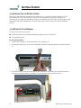
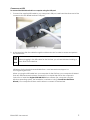
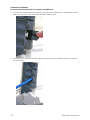
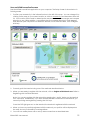
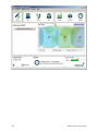
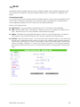
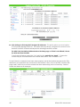
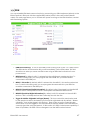
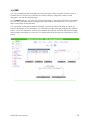
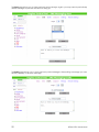
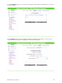
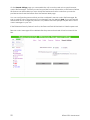
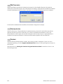
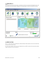
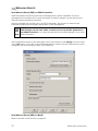
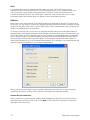
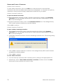
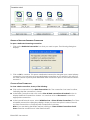
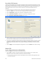
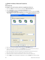
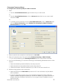
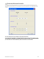
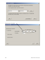
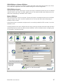
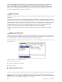
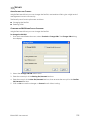
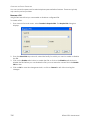
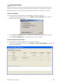
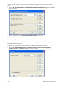
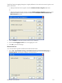
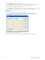
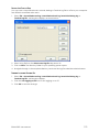
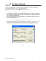
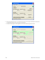
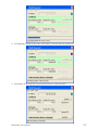
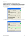
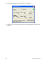
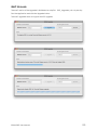
DELETING A DATA CONNECTION
To delete a connection:
1. In Profile Manager, click on the Connections tab.
2. Select an icon from the Existing icons screen.
3. Click on Delete. You are prompted to confirm the deletion.
4. Click on Yes to confirm the deletion, or click on No to exit without deletion.
HIDING AN ICON
The available data connections display in the BGAN LaunchPad Data connections window. You
can hide an icon if required using Profile Manager.
To hide an icon:
1. In Profile Manager, click on the Connections tab.
2. Select an icon you want to hide, and select the Hide icon radio button. The selected icon is
grayed out, and does not display when you open the BGAN LaunchPad Data connections
window.
Note: To restore the icon, repeat step 2 and deselect the Hide icon radio button.
3. If required, repeat step 2 for any other icon you want to hide.
104
BGAN 9201 User Manual
SECURITY
ABOUT SECURITY AND CONTROL
Using BGAN LaunchPad, you can change the SIM PIN, and enable a PIN to give a high level of
management control over security.
The Security and Control options are as follows:

Changing the SIM PIN

Enabling a PIN
CHANGING THE SIM PIN AND FACILITY PASSWORD
Using BGAN LaunchPad, you can change the SIM PIN.
To change the SIM PIN:
1. From the LaunchPad main menu, select Terminal > Change PINs. The Change PINs dialog
box displays:
2. Select the Change SIM PIN radio button.
3. Enter the current pin in the Existing Pin/Password text box.
4. Enter the new pin in the New Pin/Password text box, then re-enter the new pin in the Confirm
Pin/Password text box.
5. Click on Ok to save the changes, or Cancel to exit without saving.
BGAN 9201 User Manual
105
CHANGING THE FACILITY PASSWORD
You can control the password for selected phone personalization features. These are typically
only used by service providers.
ENABLING A PIN
Using BGAN LaunchPad you can enable or disable a configured PIN.
To enable a PIN:
1. From Launch Pad main menu, select Terminal > Require PINs. The Require PIN dialog box
displays:
2. From the Select PIN drop-down list, select the facility for which you want to enable or disable
the PIN.
3. Click on the Enable radio button to enable the PIN, or click on the Disable radio button to
disable the PIN. Before you can disable the PIN, you must enter the current PIN in the Enable
PIN text box.
4. Click on OK to save the changes and exit, or click on Cancel to exit without saving the
changes.
106
BGAN 9201 User Manual
SOFTWARE UPGRADE
BGAN LaunchPad can check for software updates for the LaunchPad, terminal and other
software. It can check for these updates using the BGAN system or a terrestrial connection.
BGAN LaunchPad can also install the appropriate software to the terminal or computer.
CHECKING FOR UPDATES
You can set the types of upgrade you want BGAN LaunchPad to check for.
1. From BGAN LaunchPad main menu, select Update > Check for Updates. The Check for
Updates screen is then displayed:
2. In the Check for update to: section, choose which software types you want to check for.
3. Click “Check for updates now”, or exit the window to skip the check.
SOFTWARE VERSIONS AND AVAILABILITY
You can install the software upgrades that LaunchPad has found.
1. From BGAN LaunchPad main menu, select Update > Versions and Availability. The following
screen is then displayed:
BGAN 9201 User Manual
107
2. Select which software you want to download or install on the terminal or on your computer.
3. Click on Download now if the software has not already been download followed by Install
now.
4. LaunchPad will inform you when the download has completed.
Note: Make sure that a loss of power will not interrupt the download process. You should install
the terminal’s battery and fully charge it, in case there is a power outage; and connect the AC
or DC power adapter in case the battery runs flat during the download. Similarly, if your
computer is operating from a battery, make sure the battery is charged and connect the
computer’s AC power adapter or charger.
Note: if you encounter problems downloading a file, check the firewall and other settings on
your PC such as McAfee Host Intrusion Prevention. These can sometimes block FTP.
For details using the terminal upgrader, refer to the Software Upgrader section on page 117.
108
BGAN 9201 User Manual
LOG FILES
BGAN LaunchPad maintains log files that detail the commands sent to the terminal, and the
responses obtained from the terminal. BGAN LaunchPad also records any unsolicited events
reported by the terminal. LaunchPad maintains four types of log file:

Event log file – reports details of all command and responses exchanged between BGAN
LaunchPad and the Terminal.

Network log file – reports network activity-related information, such as network usage, QoS
information, and unsolicited alerts reported by the network.

Debug log file – LaunchPad debug info

Terminal log file – generated by the terminal, and can be accessed from LaunchPad.
You can do the following for any of these log files:

Delete or Clear a Log File.

Display a Log File.

E-mail a Log File.

Print a Log File.

Save a Log File.
In addition, for event logs and network logs you can:

Turn Logging On and Off.
DELETING OR CLEARING LOG FILES
You can delete a LaunchPad event, network or debug log file, and clear a terminal log file from
BGAN LaunchPad main menu.
To delete an event, network or debug log file from your computer, do the following from BGAN
LaunchPad main menu:
1. Select File > LaunchPad event log, LaunchPad network log or LaunchPad debug log. The
Event Log dialog box is shown below:
2. Select a log file from the drop-down list.
3. Click on Delete. The log file is deleted from your computer.
BGAN 9201 User Manual
109
To clear a BGAN log file from your computer, do the following from BGAN LaunchPad main
menu:
1. Select File > Terminal Log File. The BGAN Terminal Log File Management dialog box displays,
as shown below:
2. Select a log file from the Select BGAN terminal log file drop-down list.
3. Click on Clear. The log file is cleared from your computer.
DISPLAYING LOG FILES
You can display the LaunchPad event, network or debug log file, or the Terminal log file from
BGAN LaunchPad main menu.
To display any of these files, do the following from BGAN LaunchPad main menu:
1. Select File > LaunchPad event log, LaunchPad network log, LaunchPad debug log or
Terminal Log File. The Event Log dialog box is shown below:
110
BGAN 9201 User Manual
The BGAN Terminal Logging dialog box is slightly different to the network or event log box, and
gives a choice to:
 display all the lines in the log file, check the Retrieve all lines of log file check box.
Or,
 display selected lines in the log file, uncheck Retrieve all lines of log file check box, and
enter the number of lines you want to retrieve in the Number of lines to retrieve from
BGAN terminal text box.
2. Click on Display to see the contents of the file you selected.
3. Clock the Turn logging on/off box to turn logging on or off.
4. Click OK to save the change.
EMAILING LOG FILES
You can email the log files from BGAN LaunchPad main menu.
1. Select File > LaunchPad event log, LaunchPad network log, LaunchPad debug log or
Terminal Log File. A dialog box displays, as shown below:
BGAN 9201 User Manual
111
2. Select the file to email from the drop down list.
3. Click on E-Mail to open a new message in your Email application, addressed to your support
contact and with the log file attached. You can type in a message, if required.
4. Select the file to email from the drop down list.
5. Click on E-Mail to open a new message in your Email application, addressed to your support
contact and with the log file attached. You can type in a message, if required.
PRINTING LOG FILES
You can print a log file from BGAN LaunchPad main menu.
1. Select File > LaunchPad event log, LaunchPad network log, LaunchPad debug log or
Terminal Log File. A dialog box displays, as shown below:
2. Select a log file from the drop-down list.
3. Click on Print to open your operating system's print dialog box, and print the log file.
112
BGAN 9201 User Manual
SAVING LOG FILES TO DISK
You can save a LaunchPad event, network, debug or Terminal log file to a file on your computer
from BGAN LaunchPad main menu.
1. Select File > LaunchPad event log, LaunchPad network log, LaunchPad debug log or
Terminal Log File. A dialog box displays, as shown below:
2. Select a log file from the Select event log file drop-down list.
3. Click on Save. The directory folder for your operating system opens.
4. Navigate through to the required directory, and save the log file under the selected name.
TURNING LOGGING ON AND OFF
1. Select File > LaunchPad event log, LaunchPad network log, LaunchPad debug log or
Terminal Log File. A dialog box displays.
2. Click the Turn logging on/off box to turn logging on or off.
3. Click OK to save the change.
BGAN 9201 User Manual
113
POWER-ON SELF-TEST
SATELLITE TERMINAL BOOT BEHAVIOR
When the terminal is powered up, it goes through a two-phase boot process. The first phase
loads a Minimum Boot ROM (MBR) module, which provides basic functionality, including self-test
and basic network connectivity.
When the self-test has completed with no failures detected, the MBR then proceeds to the
second phase, and loads the application module. This provides full terminal functionality.
If the applications module is not installed or is bad, a new application has to be installed. A bad
application could cause the terminal to stall in the second phase, or constantly reset. To prevent
this, the boot process can be stopped at the MBR phase, so that a new application can be
installed. This is achieved by holding down the audio button at the same time as the power
button is pressed.
If the audio button is accidentally pressed during power up, causing the boot process to stop at
the MBR phase, then simply power cycle the terminal and it will power-up through both phases
of the boot process.
If the terminal MBR module detects a failure during the self-test, it will stop the boot process and
indicate the source of the failure through the 6 LEDs used for pointing, as follow:
Pointing LED Color and Status
G
Solid green LED
R
Solid red LED
B
Blank or off LED
BG
Blinking green LED
BR
Blinking red LED
1
2
3
4
5
6
Description of Failure
Action
R
B
B
B
B
B
The main processor has failed to start
Note 1
G
BR
BR
B
B
B
The main processor has detected a fault in its
memory
Note 1
G
BR
BG
BR
B
B
The terminal SW is not properly installed
Note 2
G
BR
BG
BG
BR
B
The terminal SW is not properly installed
Note 2
G
G
BR
BR
B
B
The main processor has detected a fault in the
Ethernet interface
Note 1
G
G
BR
BG
BR
B
The main processor has detected a fault in the
USB interface
Note 1
G
G
BR
BG
BG
BR
The main processor has detected a fault on the
Note 1
114
BGAN 9201 User Manual
1
2
3
4
5
6
Description of Failure
Action
WLAN interface
G
G
G
BR
B
B
The main processor has detected a fault in the
ASIC
Note 1
G
G
G
BR
BG
BR
The main processor has detected a fault in the
transmitter
Note 1
G
G
G
BR
BR
BG
The secondary processor has detected a fault in
its memory
Note 1
G
G
G
BG
BR
BR
The secondary processor has failed to start
Note 1
Note 1: Remove all data cables and power cables from the terminal (remember to remove the
battery). Wait 30 seconds, then reconnect power and re-start the terminal. If this does not clear
the failure, follow the troubleshooting procedures below.
Note2: Re-load the terminal’s software.
TROUBLE SHOOTING BOOT MODE PROBLEMS
If a software upgrade fails, the UT will come up in boot mode and the LEDs will be lit up as
indicated in the above chart. A limitation in this mode is that the DHCP server is not enabled. If
the communication to the UT cannot be established, then you have to manually configure the
IP address of the connected PC by going to your Network Connection icon and right click and
select “Properties”. The following screen shot shows your Network Connections. You need to
select the connection that is tied to your Ethernet card (e.g. Local Area Connection 4). Right
click on the LAN connection (maybe named differently) and select “Properties”.
The following screen appears. Scroll down until you find the Internet Protocol (TCP/IP) and then
click on “Properties”.
BGAN 9201 User Manual
115
The following screen appears:
Click on the radio button that says “Use the following IP address”
The static IP address information below should be entered:
IP Address:
192.168.128.101
Subnet Mask: 255.255.255.0
Default GW: 192.168.128.100
Click on OK to confirm the entries…
To verify the connection to the terminal, open a DOS command window and at the DOS prompt
try pinging the UT by typing “ping 192.168.128.100”. If you get 4 replies back, you know you have
connectivity to the UT.
Once you have connectivity to the UT, then you can use the Hughes Upgrader to load the latest
software into the UT.
116
BGAN 9201 User Manual
SOFTWARE UPGRADER
The 9201 software upgrader for the latest release is available from the following web sites:
www.inmarsat.com/support and www.bgan.hughes.com.
INSTRUCTIONS FOR THE HUGHES 9201 SOFTWARE UPGRADER
The PC upgrader is distributed as a self extracting executable.
1. Run the exe file, which will unpack the BGAN upgrader into the c:\BGAN\a.b.c.d folder on
your computer. Note that a.b.c.d is the version of software that the upgrader will load onto
your Hughes 9201 satellite terminal.
2. Connect the Ethernet port of the BGAN modem to be upgraded to the LAN port of the PC
using a standard Ethernet cable.
3. Connect an AC/DC converter (supplied in the BGAN install kit) to the BGAN modem, if it
does not power on automatically, press the power button to turn it on.
4. Run the BGAN_Upgrader.exe file in the above folder. It will show the current terminal status. If
the New software version is higher than the Modem SW version then the unit can be
upgraded. If the PIC Info versions do not match then see the PIC upgrade section below.
5. Click the “Upgrade SW” box and then the "Upgrade" button:
BGAN 9201 User Manual
117
6. During the Upgrade process, it is imperative that the power supply and Ethernet connections
to the BGAN modem are not removed or interrupted.
7. The status and progress of the Upgrade is shown in the BGAN Upgrader window.
118
BGAN 9201 User Manual
8. The upgrade process will proceed. After about 2 minutes the unit will reboot.
9. After about 30 seconds the new Software version will be indicated.
BGAN 9201 User Manual
119
10. The terminal has been successfully upgraded, and the power and Ethernet connections can
be removed.
11. If you want to upgrade another terminal, there is no need to close the BGAN Upgrader
window. Just repeat steps 2 through 10, but omit step 4.
Note: if you encounter problems downloading a file, check the firewall and other settings on
your PC such as McAfee Host Intrusion Prevention. These can sometimes block FTP.
Note: The upgrader has to be run with Administrator privileges. If you see the following error on
Vista or Windows 7, right click on the ‘BGAN_Upgrader.exe’ and choose the option ‘Run As
Administrator’.
The following functions are also available from the pull-down menu items in the Upgrader
program:
File->
 Upgrade: upgrade modem software (same function as 5 above)
 Restore: restores the terminal software back to the version prior to the upgrade
 Upgrade PIC: upgrades only the PIC software, not the main modem software. The PIC
software is normally not part of the software release, so it is normally not upgraded at the
same time as the modem software. If the upgrader includes PIC software, then it will be
indicated in the PIC info field.
Tools->
 Configure Modem Interface: allows you to change the IP address the application uses if your
9201 has been changed from the default IP address.
 Get SW version: reads the software version loaded on your modem, and the version that is
available to be upgraded
 Reset Modem: turns the modem off and back on.
Help->
 About upgrades: shows the version number of the upgrader.
Once the upgrade is complete you can check the SW version on the Properties page of the
Web UI. You can also use the Diagnostic Report function under the LaunchPad Help pull down
window to validate that the download was successful.
120
BGAN 9201 User Manual
PIC UPGRADE
If the PIC versions do not match in the PIC Info area, you may upgrade the PIC software. You
should check the release notification to see if the PIC upgrade is required.
During the PIC Upgrade process, it is imperative that the power supply and Ethernet connections
to the BGAN modem are not removed or interrupted or the terminal may become unusable.
The PIC upgrade uses the same steps as the regular software upgrade and can be done at the
same time or separately.
1. If the new PIC version is newer than the Modem PIC version and you want to upgrade, click
the Upgrade PIC box and then click the Upgrade button:
2. During the Upgrade process, it is imperative that the power supply and Ethernet connections
to the BGAN modem are not removed or interrupted.
3. The status and progress of the Upgrade is shown in the BGAN Upgrader window.
4. The upgrade process will proceed. After about a minute the unit will reboot.
BGAN 9201 User Manual
121
5. After about 30 seconds the new Software version will be indicated.
6. The terminal has been successfully upgraded, and the power and Ethernet connections can
be removed.
122
BGAN 9201 User Manual
MAC UPGRADER
The MAC version of the Upgrader is distributed as a zip file: 9201_Upgrader_a.b.c.d_Mac.zip
Run the application and click the Upgrade button.
The MAC upgrader does not support the PIC upgrade.
BGAN 9201 User Manual
123
TROUBLE SHOOTING
Problem
Possible Cause
Possible Solution
Terminal will not turn on
Power button not pressed for
long enough
Press the button for 2 seconds
Discharged battery
Connect the AC or DC power adapter
Battery not fitted
Connect the AC or DC power adapter
Battery is defective (battery LED is
flashing red)
Replace battery
Battery temperature is outside
charging range
Battery will only be charged at
temperatures between 0°C and 45°C.
Cannot insert battery
into terminal
Battery incorrectly oriented
Ensure the battery is oriented as shown
in First Time Setup
Cannot insert USIM card
holder into terminal
USIM is not correctly seated in the
card holder
Ensure the USIM is pressed firmly into the
card holder
Card holder incorrectly oriented
Ensure the card holder is oriented as
shown in First Time Setup
Cannot lock the
terminal’s stand at the
desired protractor angle
Lock knobs are not tight enough
Ensure lock knobs are turned in the
direction shown on the knobs. Both
knobs will gradually tighten if you push
the unit to a lower angle. This can help
with locking the unit when the desired
protractor angle is close to 90 degrees.
Terminal’s lock knobs
cannot be loosened
Closing the stand has tightened
both lock knobs
Open the terminal’s stand; this will
automatically loosen the lock knobs.
The Terminal tips
forward.
The stabilizer has not been
deployed
See Terminal Stand Positioning
In a fixed installation, the
terminal will not turn on
and reconnect to the
BGAN system after a
power outage
Terminal’s automatic modes are
not set correctly
Set the automatic modes, see
Automatic Mode
The BGAN LaunchPad
will not connect to the
terminal
No interface connection
between the terminal and
computer
Ensure there is a WLAN, Ethernet or USB
connection between the terminal and
computer, see Connecting the Terminal
to the Computer
Battery does not charge
Terminal is in Boot Mode
Enhanced Security may be
enabled
124
Follow the instructions in
Troubleshooting Bootmode Problems to
recover the terminal from Boot Mode.
Try to access the UT via a browser. Enter
the security password when prompted.
BGAN 9201 User Manual
Problem
Possible Cause
Possible Solution
Cannot talk to the BGAN
terminal even though it
is on and appears to be
working
The IP address of the UT may
have been changed
From a PC cmd window enter the
ipconfig command to check the UT
address, which is shown as the Default
Gateway.
The IP address of the UT may
have been changed and DHCP
turned off
Enhanced Security may be on
The BGAN LaunchPad
will not connect to the
terminal over the WLAN
interface
Terminal will not accept
incoming ISDN calls
WLAN WEP is enabled on terminal
and the computer’s WLAN is not
programmed with the WEP key.
Power up the UT with no SIM installed.
The UT will enable the DHCP server and
should now assign the PC an address.
Use the ipconfig command to get the
Default Gateway address. This can
then be used as the UT address in
LaunchPad or the Web UI to talk to the
UT.
Try to access the UT via a browser. Enter
the security password when prompted.
Disable WEP, or use the same WEP keys
for both the terminal and computer. For
details, go to Connecting Terminal to
PC and other devices via WLAN
interface
WLAN signal is not strong enough
Locate the terminal and computer to
reduce any obstructions between
them, and locate them closer together.
The MSN programmed into the
ISDN device does not match the
MSN programmed into the
terminal
Ensure the appropriate MSN is
programmed into the ISDN device, see
Voice Telephony Services and ISDN
Data
Ensure the appropriate MSN is
programmed into the terminal, see
ISDN Equipment
Terminal will not make
outgoing ISDN calls
The ISDN interface is turned off
(Note the interface turns off
automatically when the terminal
is operating from battery power,
if no ISDN device is detected
within 5 minutes from power on)
Terminal is still in antenna pointing
mode
BGAN 9201 User Manual
Enable the ISDN interface from the
BGAN LaunchPad or web UI, see ISDN
Equipment
Alternatively, turn the terminal off, then
turn it on and immediately connect the
ISDN device
Exit antenna pointing
125
Problem
Possible Cause
Possible Solution
Terminal is connected to
the BGAN network, but
cannot obtain the
requested Quality of
Service
The terminal is not optimally
pointed at the satellite
Re-point the terminal, see Pointing the
Terminal.
Ensure the following minimum LEDs are
lit for the requested Quality of Service:
Streaming 256: 4 green LEDs
Streaming 128: 3 green + 1 red LED
Streaming 64: 2 green + 1 red LED
Streaming 32: 1 green + 1 red LED
background or standard: 1 red LED
ISDN data (64Kbps): 2 green + 1 red LED
CS voice (4): 1 red LED
Terminal does not obtain
a GPS fix
Terminal’s location limits visibility
of 4 or more GPS satellites.
See Field Service Bulletin FSB030601.pdf for instructions on
tightening chassis screws around
GPS antenna area.
You hear a continuous
beep from the terminal
when you connect an
ISDN device to the ISDN
port
The ISDN device is trying to draw
too much power from the
satellite terminal’s ISDN interface
None of the above
solutions resolve the
problem
Terminal may have a hardware
or software fault, and needs to
be re-booted.
The device you are connecting is
not an ISDN device. It might be
an Ethernet device that you are
accidentally connecting to the
ISDN port.
Move the terminal to a location where
there are few obstructions such as trees
or tall buildings, so that as much as
possible of the sky is visible; see
Obtaining a GPS fix
Only connect an ISDN device that
draws less than 70mA of current at 40V
(equivalent power 2.8W)
Make sure you connect only ISDN
devices to the ISDN port
Remove the power adapter, and
battery. Wait 30 seconds. Reconnect
the AC or DC power adapter or the
battery, and turn on the terminal.
As the terminal powers up, check the
status of the LEDs, see Satellite Terminal
Boot Behavior
126
BGAN 9201 User Manual
TECHNOLOGY OVERVIEW
GPS
The Global Positioning System (GPS) uses 24 orbital satellites to determine the position of the
Terminal anywhere on the globe.
OBTAINING A GPS FIX
In normal operation, a GPS receiver, such as that built in to the Terminal, needs to be able to
receive signals from at least four satellites so that it can then calculate a latitude, a longitude
and an altitude – this position fix is referred to as a 3-dimensional or 3-D fix. If only three GPS
satellites can be seen by the GPS receiver, then the last available altitude measurement is
assumed and the GPS receiver calculates a position fix based on latitude and longitude only.
This simpler position fix is referred to as a 2-dimensional or 2-D fix and is quicker and easier to
obtain than a 3-D fix, but may be less accurate.
The GPS receiver may take between a few seconds and 20 minutes to obtain a GPS fix,
depending on how frequently the GPS receiver is being used. The frequency of use determines
the how quickly the GPS Terminal is able to start.

Hot start  if the GPS receiver is being used frequently, (that is, in the last two hours), it is
regularly updated with data from the GPS satellites, and so only takes a few seconds to
obtain a GPS fix after being switched on.

Warm start  if a GPS receiver has not been used for more than two hours, then it will take up
to 45 seconds to obtain a GPS fix.

Cold start  if the GPS receiver has not been used for some time or is 300 km or more from
where it was last used, it can take as long as 15 minutes to obtain a valid position fix.
The time taken to obtain a valid GPS fix can also be affected by the visibility that the GPS
receiver has of the GPS satellites. The GPS system is relatively tolerant of atmospheric conditions
such as heavy cloud or rainfall. However, physical blockages, such as tall buildings or terrain can
significantly degrade the ability of the GPS receiver to obtain a fix. For this reason, ensure that
the GPS receiver has a clear view of as much open sky as possible.
GPS AND BGAN REGISTRATION
BGAN uses the accurate position and timing information obtained from GPS to help ensure
efficient registration of a BGAN Terminal with the BGAN network.
Following successful registration and providing the Terminal is left switched on and remains
stationary, the GPS is no longer needed. Periodically, the BGAN Terminal contacts the BGAN
network to inform the network that it is still switched on. In addition, the BGAN network
periodically checks each Terminal for activity, and if the Terminal has not automatically
contacted the BGAN network as described above, then the Terminal will be de-registered from
the network.
BGAN 9201 User Manual
127
ISDN
The Satellite Terminal provides an ISDN (Integrated Services Digital Network) interface to connect
devices for Circuit Switched voice and data services. It is a Basic Rate (also known as 2B+D)
interface and uses the Euro ISDN protocol. Note that the Satellite Terminal can only provide
service for one 64Kbps B-channel at a time.
DIALING AND NUMBERING
DIALING
As the ISDN numbering system follows the same pattern as the normal telephone system, dialing
is carried out in exactly the same manner as making a normal telephone call. The subscriber
number is used with the same international and area codes as any other telephone network.
MULTI-SUBSCRIBER NUMBERING (MSN)
ISDN supports Multi-Subscriber Numbering (MSN). MSN is a facility whereby more than one
telephone number can be allocated to an ISDN line. The BGAN Satellite Terminal assigns
different MSNs for Voice, 3.1KHz Audio, UDI and RDI devices. Each incoming call will be directed
to the appropriate MSN depending on the type of call. This allows to route incoming calls to the
correct ISDN device (e.g. ISDN phone, data card or Fax).
PDP CONTEXT
A Packet Data Protocol (PDP) Context defines connection aspects such as routing, Quality of
Service (QoS), security and billing between a mobile user terminal, such as the BGAN Terminal,
and a data network. PDP Contexts are essential to the General Packet Radio Service (GPRS)
system, which is used by GSM and UMTS-based 3G networks worldwide for transmitting data.
In order for a user to be able to transfer data across a network, a PDP Context must be
activated in the Terminal and associated Core Network. The procedure for this is as follows:
1. After registration with the network, the user activates a PDP Context using an application on
the computer or Terminal, and requests sufficient radio resources (that is, power and
bandwidth) to support the context activation procedure.
2. Once the resources are allocated, the Terminal sends the Activate PDP Context request to
the Core Network. This request includes key information about the mobile user's PDP address
(for example an IP address), PDP type (that is, static or dynamic address) the QoS requested
for this context, the APN of the external network to which connectivity is requested, the user's
identity (IMSI) and any necessary IP configuration parameters (for example, security settings).
3. On receiving the Activate PDP Context message, the Core Network checks the user's
subscription record to establish whether the request is valid. If the request is valid, a virtual
connection is established between the Terminal and the Core Network, and data transfer
can then take place between the Terminal and the external data network, within the scope
of the current PDP Context. The PDP Context is stored in both the Terminal and the Core
Network.
A single Terminal may have multiple PDP Contexts each with different QoS profiles. The primary
PDP Context is a PDP Context with default QoS profile attributes and is always activated first. All
other PDP Contexts with the same PDP Address are secondary PDP Contexts. Secondary PDP
Contexts share the same PDP Address and connect to the same APN but may have different
QoS profiles.
128
BGAN 9201 User Manual
WLAN
Wireless Local Area Networking (WLAN) enables two or more computers equipped with wireless
adapter cards to share resources.
A wireless network comprises of two or more computers each equipped with wireless adapter
cards forming a network. When the computers are within range of each other each computer
has access only to the resources of the other computer but not to any central server or other
resource. This type of basic configuration is known as an ad hoc network.
A more common and efficient use of a wireless network is one in which two or more computers
equipped with wireless adapter cards are linked to a WLAN Access Point. The Access Point
allows each computer to have access to shared resources, such as a broadband Internet
connection, as well as to other computers on the network. Such a configuration is known as
Infrastructure Mode. This is the default configuration for WLAN in the UT.
PERFORMANCE
The performance of a WLAN network will be influenced by several factors including the number
of users on the network, the location of the antenna, the distance from the antenna and the
degree of blocking from buildings and other infrastructure. Typical operating ranges are 200-300
meters outdoors and 30-60 meters indoors, the performance degrades gradually as the signal
strength decreases.
SSID
A wireless network is identified by a Service Set Identifier or SSID. An SSID is also referred to as a
Network Name because it is a name that identifies a wireless network. Wireless devices that wish
to communicate with each other must be configured with the same SSID. Several Access Points
can be set up using the same SSID so that users can roam from one Access Point to the other
without losing network access. The SSID is broadcast so that any wireless device in range can
read the SSID and ask permission to associate with it. The SSID is not intended as a security
measure  it is used only to identify different networks.
BGAN 9201 User Manual
129
TECHNICAL SPECIFICATIONS
Weight
2.8 Kg (terminal with battery)
Dimensions
27.5 cm x 34.5 cm x 5.0 cm
Battery Life
Transmit: 162 Mbytes
(actual performance
based on range of
factors and actual
usage)
Receive: 864 Mbytes
Humidity
95% RH at +40˚C
Temperature
-25˚C to +60˚C operating
36 hours standby time
(standard battery)
-25˚C to +80˚C storage
Water & Dust
IP-55 standard
Transmitter power
20dBW EIRP maximum
Antenna
characteristics
Nominal gain 15dBi, nominal 3dB beam width ±20 degrees.
The Satellite Terminal carries a warranty for 12 months from the date of sale. Contact you Service
Provider if you have questions about the warranty, or need to return the terminal for repair.
130
BGAN 9201 User Manual
DECLARATION OF CONFORMITY
Hughes Network Systems, LLC, of 9605 Scranton Road, San Diego, CA, 92121, USA, declares
under our sole responsibility that the product Hughes 9201 Satellite IP Terminal to which this
declaration relates, is in conformity with the following standards and/or other normative
documents:
ETSI EN 301 444 , ETSI EN 300 328, ETSI EN 301 489-1, ETSI EN 301 489-17, ETSI EN 301 489-20, IEC
60950-1, Council Recommendation 1999/519/EC.
We hereby declare that all essential radio test suites have been carried out and that the above
named product is in conformity to all the essential requirements of R&TTE Directive 1999/5/EC.
The conformity assessment procedure referred to in Article 10 and detailed in Annex [III] or [IV] of
Directive 1999/5/EC has been followed with the involvement of the following Notified Body(ies):
BABT, Balfour House, Churchfield Road, Walton-on-Thames, KT12 2TD, UK.
Identification mark: 0168 (Notified Body number).
The technical documentation relevant to the above equipment will be held at:
Hughes Network Systems, LLC, 9605 Scranton Road, San Diego, CA, 92121, USA
Signed by Peter Sroka (Senior Technical Director, August 12, 2005) and Bill Lindsay (Senior
Program Manager, August 12, 2005).
EU ROHS (RESTRICTION OF HAZARDOUS SUBSTANCES) DIRECTIVE
9201 units marked RoHS (MCN 3500058-0001) meet the European Union (EU) directive on
Restriction of Hazardous Substances.
EU WEEE (WASTE ELECTRICAL AND ELECTRONIC EQUIPMENT) DIRECTIVES
The European Union (EU) directive on waste electrical and electronic equipment mandates
recycling of electrical and electronic equipment throughout the EU by August 13, 2005.
Unless otherwise noted, all products, assemblies, and sub-assemblies manufactured by Hughes
and its sub-contractors will be compliant with this directive and any subsequent revisions or
amendments. This product carries the WEEE label below to demonstrate compliance.
For addition information, contact Hughes Network Systems at: www.hughes.com.
BGAN 9201 User Manual
131
GLOSSARY
APN: An Access Point Name (APN) provides access to an external network. By default, the SIM
Card in your terminal is configured with the APN of your Internet Service Provider. You may
want to configure further APNs if you have arranged with your Service Provider to use more
than one SIM Card.
ARP: Address Resolution Protocol is used to find out the physical Ethernet address of a host.
BGAN Satellite Terminal: Referenced throughout this document as the Satellite Terminal, “The
Terminal” or the UT (User Terminal)”, this device implements and manages BGAN satellite
communications between your computer and your Service Provider’s network.
CID: Context Identifier for a PDP context.
Quality of Service: Quality of Service (QoS) assigns a level of priority to certain types of data
traffic, in particular high bandwidth applications such as video and multimedia. QoS
attempts to maintain a guaranteed throughput level, and minimize error rates and end to
end latency, so providing a higher level of service than "best effort" protocols.
DHCP: Dynamic Host Control Protocol – a protocol used to assign an IP address to a host.
DNS Server: The Domain Name System (DNS) is an Internet service that is required because the
Internet does not recognize the text-based Web address or email address that you type into
your Web browser or email application. All or part of a Web address or an email address is a
domain name, and DNS translates this domain name into an IP address that is recognized by
the Internet.
A DNS Server holds a database of domain names and IP addresses, so that when you enter
a Web address or email address, you are directed to the correct IP address over the Internet.
Error correction: Error correction ensures that very little data is lost during transfer by asking for
dropped packets to be resent. However, because it holds subsequent data whilst the
packet is being resent, you may notice some jitter or delay in the received data. This is
normal for most data types.
For real-time applications, such as Voice over IP (VoIP) or video, it is recommended that you
remove error correction. Removing error correction minimizes delay and jitter..
Ethernet: Ethernet is a local area networking method used widely throughout the computer
industry. It is one of the three communications interfaces supported by the Satellite Terminal.
Fault Code: A number which uniquely references an error in a hardware or software system. In
the Satellite Terminal, if there is a fault detected, the fault code and a description are
displayed in suitable LaunchPad windows.
GPS: Global Positioning System. The GPS receiver in the Satellite Terminal receives signals from
the constellation of GPS satellites. It uses these signals to determine the Terminal’s location on
earth. That location is used during registration to gain access to the BGAN system.
Header Compression: A header is the component of a data packet that precedes the data that
you are sending. The header contains information such as source and destination address,
error checking and other administrative details. In most data types this does not noticeably
affect the data transmission rates. However in multimedia applications such as voice and
video, the header can significantly affect performance.
Inmarsat recommends that you switch on header compression for multimedia applications,
such as video.
IP Address: An Internet Protocol address, or IP address, is a number that identifies the computer
that is sending or receiving information transmitted over the Internet. An IP address is made
up of four groups of numbers between 0 and 255, separated by periods. For example,
207.115.79.4 is an IP address. In the BGAN system, IP addresses can be dynamic or static.
132
BGAN 9201 User Manual
Dynamic IP Address: A dynamic IP address is a temporary address that is assigned by your
Internet Service Provider (ISP) when you connect to the Internet. If you do not need a
permanent IP address, Inmarsat recommends that you obtain a dynamic IP address.
Normally, individual users of the Internet use a dynamic IP address.
Static IP Address: A static IP address is assigned permanently, and is used every time you
connect to the Internet. Normally, companies and other organizations that have their
own networks use static IP addresses.
MSN: Multiple Subscriber Number, for ISDN call types.
PDP: Packet Data Protocol.
SIM Card: Your Service Provider supplies you with a Subscriber Identification Module (SIM) Card
or a Universal Mobile Telecommunications System Subscriber SIM (USIM) Card.
A SIM or USIM Card is a card commonly used in a GSM phone. The card holds a microchip
that stores information and encrypts voice and data transmissions, making it difficult to listen
in on calls. The USIM Card also stores data that identifies the caller to the Service Provider.
Standard Connection: A standard connection is charged by volume of data sent. The
bandwidth you are allocated depends on terminal type and network availability, but is
always ‘best effort’, that is, you are allocated bandwidth depending on your requirements
and the requirements of other users of the BGAN network, or BGAN Terminal. This connection
class is suitable for most data types, other than multimedia.
Streaming: A streaming connection is charged by time. You are charged for the amount of time
the connection is active. Streaming enables multimedia data, such as video, to be sent in a
continuous data stream and converted into sound and pictures.
Symmetrical Rate: The rate at which streaming data is transmitted, in kilobits per second (Kbps).
This rate applies to transmitted (uplink) and received (downlink) data.
Desired Symmetrical Rate: From the drop-down list, choose the desired data rate for your
Streaming connection. This can be 32 Kbps, 64 Kbps, 128 Kbps, 176 Kbps or 256 Kbps. This
figure is guaranteed, unless the connection cannot meet this requirement because of
bandwidth restrictions. In this case, the rate defaults to the minimum symmetrical rate.
Minimum Symmetrical Rate: From the drop-down list, choose the minimum data rate that
you are prepared to accept for your Streaming connection. This can be 32 Kbps, 64
Kbps, 128 Kbps, 176 Kbps or 256 Kbps. This rate must be the same or lower than the
Desired Symmetrical Rate. If the connection cannot meet this requirement, an error
message is displayed.
TE: Terminal Equipment, e.g. your computer or ISDN phone.
Traffic Flow Template: A Traffic Flow Template, also called an Application Template, is a series of
data filters such as IP address or port number that allow the Core Network to classify packets
received from an external network into the correct PDP Context. When incoming data
arrives at an access point in the core network, a packet classifier will make a PDP Context
selection based on the Traffic Flow Template, and map the incoming data packets into the
PDP Context with the correct QoS attributes. The use of a Traffic Flow Template allows
multiple PDP Contexts to be associated with the same PDP address.
USIM Card: Your Service Provider supplies you with a Subscriber Identification Module (SIM) Card
or a Universal Mobile Telecommunications System Subscriber SIM (USIM) Card.
A SIM or USIM Card is a card commonly used in a GSM phone. The card holds a microchip
that stores information and encrypts voice and data transmissions, making it difficult to listen
in on calls. The USIM Card also stores data that identifies the caller to the Service Provider.
UT: User Terminal; BGAN Satellite Terminal.
Virtual Private Network: A Virtual Private Network (VPN) enables remote offices or users to gain
secure access to their organization's network over the public telecommunications network.
This provides the benefits of remote access without the expense of dedicated leased or
owned lines. VPNs work by using tunneling protocols, such as L2TP, to encrypt data at the
BGAN 9201 User Manual
133
sending end, and decrypt the data at the receiving end. This "tunnel" cannot be accessed
by data that is not properly encrypted.
134
BGAN 9201 User Manual