1
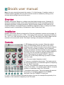
Braids user manual
Note: this user manual documents the version 1.5 of the firmware. If another version is
installed, please upgrade! You can find out which version is installed by clicking on the
encoder and scrolling to the end of the menu.
Overview
Mutable Instruments’ Braids is a voltage-controlled digital sound source. It features 33
waveform synthesis models, which cover techniques such as FM, wavetable synthesis,
waveguide synthesis or analog emulation. Most synthesis models are built with one or
several oscillators connected through crossfaders, modulators, filters, or delay lines. Each
synthesis model is controlled by 2 parameters, called Timbre and Color.
Installation
Mutable Instruments’ Braids is designed for Eurorack synthesizer systems and occupies 16
HP of space. It requires a -12V / +12V / +5V supply (2×8 connector), consuming 15mA from
the -12V / +12V rails and 85mA from the +5V rail. The red stripe of the ribbon cable must be
oriented on the same side as the “Red stripe” marking on the printed circuit board.
Controls
A: LED display and rotary encoder. When the module
starts, the LED display shows the name of the active
synthesis model, and the encoder can be used to select a
model. Click the encoder to display a list of additional
settings and options. Click the encoder to select an option
and modify its value. Once the value has been modified to
your liking, click the encoder to get back to the list of
options. Selecting the first option (“WAVE”), saves to
memory the current setup and brings you back in model
selection mode.
B, C: Fine and coarse frequency control.
D: Frequency modulation attenuverter. This knob controls
the amount and polarity of modulation applied to frequency,
from the FM CV input jack.
E: Timbre. This parameter controls the main evolution and
motion of the timbre – for example pulse width for a square
oscillator or modulation index for a FM model.
F: Modulation attenuverter. This knob controls the amount
and polarity of modulation applied to the TIMBRE
parameter, from the TIMBRE CV input jack.
G: Color. This knob controls a second dimension of sound, for example the symmetry of an
oscillator or the modulation frequency for a FM model.
Inputs and outputs
TRIG: This trigger input serves three purposes. 1/ Braids’ physical models need to be
“excited” by an impulse on this input to give birth to a sound. 2/ The other models will treat
the trigger as a reset signal, bringing the phase of the oscillator(s) to 0. 3/ This input can also
be used to trigger an internal AD envelope applied to the TIMBRE parameter, to create
sound animation and attacks without an external envelope module.
V/OCT: 1V/Oct frequency CV input.
FM: Frequency modulation CV input – the scale and polarity of this signal is set by the FM
attenuverter.
TIMBRE and COLOR: Control voltages for the Timbre and Color parameters. A value of 0V
corresponds to the minimum position of the knob. A value of +5V corresponds to the
maximum position of the knob. This CV is offset by the current position of the knob.
OUT: Signal output. Loudness is model-dependent – for example a pure sine wave is always
at maximum amplitude; while a ring-modulated sine-wave will have peaks and valleys due to
amplitude modulation, and will thus sound quieter.
Models
CSAW
This model is inspired by a quirk/defect of the Yamaha CS80 sawtooth wave shape,
consisting of a fixed-width “notch” after the raising edge. The width of the notch can be
controlled by TIMBRE; and its depth and polarity can be controlled by COLOR – producing
phasing effects.
/\/|-_-_
This model produces the classic waveform trajectory from triangle to sawtooth to square to
pulse found in synthesizers such as the RSF Kobol or the Moog Voyager. TIMBRE sweeps
through the waveforms. COLOR morphs from several tonal characters by increasingly
removing the high-frequencies with a 1-pole filter, and recreating them with a waveshaper.
/|/|-_-_
This model blends a sawtooth wave with dephasing control, with a square wave with PWM.
TIMBRE controls the dephasing amount or pulse width, and COLOR morphs the waveshape
from sawtooth to square.
SYNC
This model synthesizes the classic 2-oscillator hardsync patch, with both oscillators emitting
square waves. The main oscillator frequency controls the master frequency. The interval
between master and slave is controlled by TIMBRE. COLOR controls the balance between
the two oscillators.
FOLD
This model is built with sine and triangle oscillators sent into a wavefolder. TIMBRE controls
the wavefolder strength, and COLOR controls the balance between the sine and triangle
signals sent to it.
_|_|_|_|_
This digital synthesis algorithm generates a smooth sequence of waveforms, transitioning
from a sine wave to a Dirac comb, as controlled by TIMBRE. The intermediary steps are
reminiscent of a single formant. Two such waveshapes are blended together, with the
detuning amount controlled by COLOR.
/|/| x3, -_-_ x3
Three sawtooth (or square) oscillators which can be individually tuned. COLOR and TIMBRE
control the relative frequency of the second and third oscillator with respect to the main
oscillator. These two controls are quantized to “snap” on musical intervals like octaves or
fifths.
RING
Three sine wave oscillators are ring-modulated together, and colored by a waveshaper. The
main oscillator frequency controls the frequency of the first sine wave, and TIMBRE and
COLOR control the relative frequency of the second and third sine waves.
/|/|/|/|
This model simulates a swarm of 7 sawtooth waves. TIMBRE controls their detuning, and
COLOR applies a high-pass filter to the resulting sound.
/|/|_|_|_
This model generates a sawtooth waveform, and sends it into a comb filter (tuned delay
line). The frequency of the delay line tracks the frequency of the sawtooth oscillator, with a
transposition controlled by the TIMBRE knob. COLOR selects the feedback amount and
polarity: at 12 o’clock, no feedback is applied. From 12 o’clock to 5 o’clock, positive feedback
is increasingly applied. From 12 o’clock to 7 o’clock, negative feedback is progressively
applied.
TOY*
This model traverses a space of timbres typical of (circuit-bent) electronic musical toys.
TIMBRE simulates an alteration of the toy’s clock rate, while COLOR creates glitches or
short-circuits on a converter or memory chip’s data lines.
ZLPF, ZPKF, ZBPF, ZHPF
This family of models directly synthesize in the time-domain the response of a low-pass,
peaking, band-pass or high-pass filter excited by classic analog waveforms. Rather than
synthesizing the waveform and filtering it (which is what a VA synthesizer would do), this
approach directly aims at building the filtered waveshape from scratch. This technique has
been used in the Casio CZ or the Roland D series, but is extended here to cover different
filter types and waveshapes. TIMBRE controls the cutoff frequency of the filter. COLOR
continuously modifies the waveshape, from saw to square to triangle.
VOSM
This model uses a combination of 3 oscillators arranged in a clever ring-modulation/hardsync
patch to emulate formant synthesis – a technique named VOSIM and described by Kaegi
and Tempelaars. COLOR and TIMBRE control the relative frequencies of the two formants.
VOWL, VFOF
Both models synthesize vowel sounds. VOWL is a faithful recreation of early computer
speech synthesis programs. VFOF uses a simplified version of Rodet’s FOF synthesis
technique. Both have the same control layout: TIMBRE controls the vowel, morphing
between a, e, i, o, u. COLOR shifts the formants in frequency. Main oscillator frequency and
COLOR can be used altogether to simulate age and gender transformations.
FM, FBFM, WTFM
Three flavors of 2-operator phase-modulation synthesis. TIMBRE controls the modulation
amount. COLOR controls the relative frequency interval between modulator and carrier. FM
is a well-behaved implementation. FBFM uses feedback from the carrier to itself to produce
harsher tones. WTFM uses two feedback paths, from carrier to modulator and carrier to itself
to achieve droning, unstable tones.
BELL
This model established by Risset uses additive synthesis to recreate the tone of a bell.
TIMBRE controls the damping of the sound; and COLOR the inharmonicity of the sound.
This model needs to be “excited” by a trigger signal (or raising edge of a gate signal).
DRUM
This variant of the *BELL* model uses different parameters (partials frequencies and
amplitudes) to generate a sound reminiscent of a metallic drum. TIMBRE controls the
damping and COLOR the brightness.
PLUK
Raw plucked string synthesis. TIMBRE controls the damping, COLOR the plucking position.
This model needs to be “excited” by a trigger signal.
BOWD
Bowed string modeling. TIMBRE controls the friction level, COLOR the bowing position. A
trigger or gate signal is required. Note that this model does not include a body filter – which
would be necessary to simulate an actual string instrument.
BLOW, FLUTE
Reed or flute instrument model. TIMBRE controls the air pressure, COLOR the geometry of
the instrument. Note that this model does not include a filter – which would have been
necessary to simulate an actual instrument.
WTBL
WTBL is a classic implementation of wavetable synthesis. TIMBRE sweeps the wavetable,
and COLOR selects one of the 20 wavetables to play with. The waveforms are interpolated
when traveling through a wavetable, but not when switching from one table to another.
WMAP
WMAP is a two-dimensional implementation of wavetable synthesis. 256 waveforms have
been laid out in a 16×16 grid, so that adjacent waveforms are similar sounding. The TIMBRE
parameter scans the table in the X direction, and the COLOR parameter scans the table in
the Y direction, with smooth interpolation across the two directions.
WLIN
WLIN allows one dimensional scanning through the entirety of Braids’ wavetables. TIMBRE
moves through the waves, while COLOR selects the interpolation method. When COLOR is
at 7 o’clock, no interpolation is applied. When COLOR is at 10 o ‘clock, interpolation is
applied between samples, but not between waves. When COLOR is at 12 o’clock,
interpolation is always applied. When COLOR goes past 12 o’clock, interpolation is applied
between waves, but the resolution of the playback resolution is decreased.
WTx4
This mode is a 4-voice variant of WLIN. TIMBRE morphs through a small selection of 16
waves. COLOR selects the harmonic structures between the 4 voices – from a predefined
set of chords. When COLOR is at 7 o’clock, all voices are playing the same note with a
variable amount of detuning, creating a thick chorus effect.
NOIS
This model filters white noise with a state-variable filter. The main oscillator frequency
controls the cutoff frequency of the filter. TIMBRE controls the resonance of the filter.
COLOR realizes a crossfade between the low-pass and high-pass outputs of the filter.
TWNQ
This “Twin Peaks” model generates white noise and process it with two band-pass filters
(resonators). TIMBRE controls the Q factor of the filters, and COLOR changes their spacing.
The frequency of both filters track the main frequency.
CLKN
This model generates random samples at a given rate, determined by the main pitch control.
TIMBRE controls the periodicity of the generator (up to a 2 samples cycle), and COLOR its
quantization level (from 2 distinct values to 32 distinct values).
CLOU, PRTC
These granular synthesis models create natural textures by mixing short grains of windowed
sine waves (CLOU) or short decaying “pings” (PRTC). The frequency of the grains is
controlled by the main frequency control, but is randomized by an amount proportional to the
COLOR control. TIMBRE controls the density and overlap of the grains.
QPSK
This model generates – in the audio frequency range – the kind of modulated signals used in
digital telecommunication systems. The main oscillator frequency is the carrier frequency.
The bit-rate is controlled by the TIMBRE knob. The COLOR knob sets an 8-bit value which is
modulated into the carrier using QPSK modulation. A 16-byte synchronization frame is sent
on every trigger/gate, or every 256 data bytes.
Options
BITS selects the bit-depth of the data sent to DAC.
RATE selects the refresh rate of the DAC. Note that a handful of models are internally
rendered at 48kHz (instead of 96kHz); so the difference between 48kHz and 96kHz might be
inexistent for the most complex models. Note also that reversely, to reduce aliasing, the
simplest models are rendered internally at 192kHz or 384kHz.
TSRC selects a trigger source. EXT. uses the gate/trigger jack; AUTO additionally tracks
changes in the V/OCT frequency input larger than a semitone and generates a trigger on
each of these. This allows, for example, the physical models to be controlled by a note
sequencer which does not provide gate outputs.
DLY applies a delay between the moment the trigger is received and the moment the note is
“struck” on the physical models. We have observed that some CV-gate converters or
sequencers sometimes have slow settling times, or have a short timing errors between the
refresh of their analog and digital outputs. Delaying the processing of the trigger allows the
physical model to sample the accurate CV rather than a fluctuating one – which can cause
unwanted glitches or portamento-like effects at note onsets.
TDST selects what happens when a trigger is received on the TRIG input. SYNC simply
resets the phase of the oscillator to zero. TIMB applies an AD envelope to the TIMBRE
parameter. LEVL applies an AD envelope to the signal level (like a digital VCA). Finally,
BOTH applies both a timbre and level modulation with the internal AD envelope.
TENV selects a preset shape for the internal AD envelope. This envelope is triggered by the
TRIG input, and its destination is selected by the TDST parameter described in the previous
paragraph.
META allows the synthesis model to be selected by the FM CV. When this mode is active,
frequency modulation through the FM CV input, its attenuvertor, and the FINE knob are no
longer possible – but is replaced by CV-controlled model selection. This option is great for
creating sequences featuring the different synthesis models. Keep in mind that
discontinuities might be heard when switching from one model to the other! The EDIT
encoder can still be used to scroll through synthesis models; and the CV applies to the FM
input allows you to scroll forward (positive voltage) or backwards (negative voltage) in the
list.
RANG chooses the range of the “coarse” knob. EXT. adjusts the range of this knob +/- 4
octaves around the note received on the V/Oct input. Because of this, when no frequency
CV signal is sent to the module (which would be the equivalent to sending a CV of 0V –
corresponding to a very low note!), the coarse button will have a bias towards low
frequencies, which might not always be desirable. FREE adjusts the range of the coarse
knob to +/- 4 octave centered around C3 (261.5 Hz). This setting is recommended when the
module is used with no external signal on the V/Oct CV input. XTND (extended) provides a
larger frequency range, but disables accurate V/Oct scaling as a side effect. The last option
(440) locks the oscillator frequency to 440 Hz exactly – helpful for tuning another VCO.
OCTV is a transposition (by octave) switch.
QNTZ applies a quantification to the incoming V/Oct signal. The frequency can either be
quantized to semitones or to quarter tones. It is still possible to create smooth modulations of
the frequency, such as vibratos, by using the FM input – which is not quantized.
FLAT applies a detuning in the lower and higher frequencies, to recreate some of the tuning
imperfections of VCOs.
DRFT recreates the imperfections of a disastrously designed VCO, by combining power
supply hum, power supply fluctuations due to poor digital section decoupling and noise and
temperature instabilities. The combination of these factors is unique to each module built.
SIGN applies glitches/waveform imperfections to the output signal. The exact behavior of
this option is unique to each module built.
BRIG adjusts the screen brightness.
Calibration
Braids uses digital processing to scale its input control voltages. To calibrate the unit,
disconnect any signal from the FM input, and connect the note CV output of a well-calibrated
keyboard interface or MIDI-CV converter to the V/OCT input. Move the “Coarse” and “Fine”
knobs to 12 o’clock position. Go to CAL. in the options list, and keep the encoder pressed for
1s (this is not an option you want to select by mistake during a performance !). The screen
displays >C2 . Input a CV corresponding to a C2 note (1V). Click on the encoder. The screen
displays >C4 . Input a CV corresponding to a C4 note (3V). Click on the encoder to finish
calibration. Because Braids uses this software calibration procedure, it is compatible with the
1.2V/Oct standard too! Here is a tip: you can very well perform the calibration procedure with
another pair of notes 2 octaves apart, and with the COARSE knob in another position. This
can be used to shift up or down the range of the COARSE knob.
Toys
Following CAL. in the menu is a screen showing a visual representation of the internal ADC
readings for the TIMBRE, COLOR, V/OCT and FM inputs. This page is helpful for visualizing
the polarity and range of incoming CV signals.
The next option shows a scrolling line of text. TIMBRE controls the scrolling; and a
gate/trigger can be used to scroll the text left by one column. To edit the text, keep the
encoder pressed for more than 1s. Rotate the encoder to select the first character. Click to
move to the next character and continue editing. Once the line of text has been composed,
select the last character (all segments lit) to confirm. At any time, you can also hold the
encoder to leave the edit mode.
Firmware update procedure
Unplug all CV inputs/outputs from the module. Connect the output of your audio
interface/sound card to the FM input. Set the FINE knob to 12 o’clock, and the FM
attenuverter to 5 o’clock. Power on your modular system with Braids’ encoder pressed. The
screen will show _RDY, with a “snake” pattern on the first character.
Make sure that no additional sound (such as email notification sounds, background music
etc.) from your computer will be played during the procedure. Make sure that your
speakers/monitors are not connected to your audio interface – the noises emitted during the
procedure are aggressive and can harm your hearing. On non-studio audio equipment (for
example the line output from a Desktop computer), you might have to turn up the volume to
the maximum.
When you are all set, play the firmware update file into the module. The display shows the
number of data packets received. The firmware contains between 90 and 112 packets, and
the unit reboots after the last packet has been received. In case the signal level is too weak,
the unit will display @SYN. Try adjusting the position of the FM attenuverter, click the
encoder and retry from the start of the update file. The unit displays @CRC if a data packet
is corrupted. It is suggested in this case to retry the procedure from another computer/audio
interface, and to make sure that no piece of equipment (equalizer, FX processor) is inserted
in the signal chain. Hackers and modders will be happy to know that Braids can also be
reprogrammed with a USB->serial adapter and stm32loader.py, and that the board has a
mini-JTAG connector.
Warranty
This product is covered by Mutable Instruments’ warranty, for one year following the date of
manufacture. This warranty covers any defect in the manufacturing of this product. This
warranty does not cover any damage or malfunction caused by incorrect use – such as, but
not limited to, power cables connected backwards, excessive voltage levels, or exposure to
extreme temperature or moisture levels.
The warranty covers replacement or repair, as decided by Mutable Instruments. Please
contact our customer service ([email protected]) for a return authorization
before sending the module. The cost of sending a module back for servicing is paid for by
the customer.
Mutable Instruments encourages modding and hacking, but we will not service modified units
or provide any assistance in the realization of mods. We provide an “unbricking” (firmware
reinstallation and reinitialization) service in the event of a failed firmware upgrade procedure.
We do not “unbrick” devices if a custom firmware has been installed on them.