1
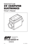
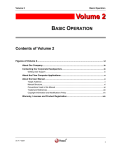
Last Updated: 04-April-2012 TB-990101D Technical Bulletin, Communicating with Instromet Q.Sonic Ultrasonic Gas Flowmeters OMNI FLOW COMPUTERS, INC. 12620 West Airport Boulevard, Suite 100 Sugar Land, Texas 77478 United States of America Phone-281.240.6161 Fax: 281.240.6162 www.omniflow.com 52-0004-0001/Rev D Page 1 of 14 TB-990101D Communicating with Instromet Q.Sonic Ultrasonic Gas Flowmeters NOTE: User Manual Reference - This Technical Bulletin complements the information contained in the User Manual Volume 3 Revision 23/27 Configuration and Advanced Operation. Table of Contents Scope ............................................................................................................................................3 Abstract .........................................................................................................................................3 Q.Sonic® Flow Meter Theory of Operation.............................................................................3 OMNI Flow Computer Logic...................................................................................................3 Wiring Installation...................................................................................................................5 Flow Meter Configuration .......................................................................................................6 Flow Computer Configuration ................................................................................................6 Miscellaneous Configuration Meter Run Settings ..................................................................6 Meter Run Setup Entries........................................................................................................7 Flow Computer Database Addresses and Index Numbers ....................................................8 Flow Computer User Displays..............................................................................................12 SV Module Serial Communications Port ..............................................................................12 Meter Run Data....................................................................................................................13 Figures Figure 1. Flow Computer Logic Flow Diagram for the Q.Sonic® Ultrasonic Gas Flow Meter .......4 Figure 2. Example of Wiring Q.Sonic Flowmeter to OMNI Flow Computer's RS-485 Port #1 of an SV Module................................................................................................................................5 52-0004-0001/Rev D Page 2 of 14 TB-990101D Communicating with Instromet Q.Sonic Ultrasonic Gas Flowmeters Scope This Technical Bulletin applies to firmware revisions 23.74+ and 27.74+ of OMNI 6000/OMNI 3000 Flow Computers for gas flow metering systems. Abstract The Q.Sonic® ultrasonic flow meter determines the linear gas velocity through the meter tube by using multiple acoustic pulse reflection paths. The Q.Sonic® analyzes these paths employing the Absolute Digital Time Travel (ADTT) measurement method. The OMNI Flow Computer totalizes either the flow meter pulse input signal or the profile corrected gas velocity data, received from the Q.Sonic®, to calculate the actual flow rate of gas. The OMNI compensates temperature expansion effects on the flow meter tube by equaling the flow to the profile corrected gas velocity multiplied by the temperature compensated tube area. If required, it can also directly use the non-compensated flow rate value transmitted by the ultrasonic meter as the actual flow rate. NOTE 1: Communicating With Instromet® Q.Sonic® Ultrasonic Flow Meters – The Instromet® Q.Sonic® ultrasonic flow meter measures gas flow with acoustic pulse reflection paths by using the Absolute Digital Time Travel (ADTT) method. This device communicates with OMNI Flow Computers via OMNI’s ‘SV’ process I/O combo module using a proprietary protocol with a fixed baudrate of 4800. To use the scaled pulse output of the Instromet flow meter, the flow computer must either have one (1) ‘A’, ‘B’ or ‘E’ combo module installed. Q.Sonic® Flow Meter Theory of Operation Instromet’s® ultrasonic gas flow metering technology incorporates multiple pairs of transducers into a smart digital inferential instrumentation device. The device is installed into a gas pipeline system to measure gas flow. Each pair of transducers emits ultrasonic (acoustic) pulses that travel bi-directionally, in either a single (axial or diagonal) or double (swirl) reflection path, to and from each transducer in the pair. The flow meters apply the Absolute Digital Time Travel (ADTT) method of ultrasonic pulse analysis, which is based on the fact that pulses travel (between a transducer pair) faster downstream with the flow than upstream against the flow. The gas flow velocity is determined from this upstream/downstream travel time differential of the ultrasonic pulses within the multiple reflection paths. When there is no gas flow in the pipeline, the upstream and downstream travel times are the same; i.e., the time differential is zero (0). The Q.Sonic® flow meter employs three (3) or five (5) transducer pairs with a minimum of one axial path and two swirl paths. This configuration allows for unique combinations of reflection paths to best take into account the different effects of gas flow profile variations, including swirl in the pipeline. The gas velocity can be determined for bi-directional (forward or reverse) fluid flow. OMNI Flow Computer Logic The OMNI Flow Computer can determine the actual flow rate from data either received serially from the Q.Sonic® flow meter or from a live pulse frequency signal input, if one has been connected and assigned. Totalization will be based on the flow pulse frequency input when the flow transmitted by the Q.Sonic® is in the correct direction (forward/reverse) and the pulse frequency is within limits. This live signal will also be used in the event of a communications failure between the Q.Sonic® and the OMNI. However, in order for the OMNI to use the pulse frequency signal, it must be wired to the Q.Sonic® and an I/O point assigned in the flow computer configuration. The flow computer will temperature compensate the meter tube area and calculate flow rate based on the profile corrected velocity of the gas transmitted serially by the flow meter (Figure 1). If the calculated flow rate is not within reasonable limits, the OMNI will directly use the transmitted flow rate as the actual flow rate. 52-0004-0001/Rev D Page 3 of 14 TB-990101D Communicating with Instromet Q.Sonic Ultrasonic Gas Flowmeters Start Q. Sonic Communications OK? No Yes Set Q. Sonic Communicati Failed Alarm on Clear Q. Sonic Communication Failed Alarm Is Transmitted Flow Rate in the Correct Direction? No Yes No Are Pulse I/O Assigned? No Set Pulse Signal Suspect Alarm No Set Pulse Signal Suspect Alarm Are Pulse I/O Assigned? Yes Yes Is Pulse and Q. Sonic Flow Rate within Limits? Yes No Clear Pulse Signal Suspect Alarm Is the Flow Based on Gas Velocity within limits? Yes Disable Totalizing Pulse AS Primary Set Run as Inactive No Yes Clear Flow Delta Alarm Set Flow Delta Alarm Calculate Actual Flow Based on Transmitted Flow Rate Clear Flow Delta Alarm Calculate Actual Flow Based on Gas Velocity & Temp Comp Area Calculate Actual Flow Based on Pulse Input Signal End Figure 1. Flow Computer Logic Flow Diagram for the Q.Sonic® Ultrasonic Gas Flow Meter 52-0004-0001/Rev D Page 4 of 14 TB-990101D Communicating with Instromet Q.Sonic Ultrasonic Gas Flowmeters Wiring Installation NOTES: Serial Data Communications – The serial interface between these devices is 2-wire RS485 mode utilizing a proprietary protocol at a fixed baudrate of 4800. All versions of the meters must be set for 4800 baud to communicate properly with the flow computer. Setting Up and Wiring to OMNI Combo Modules – In order to communicate with Q.Sonic® ultrasonic flow meters, the OMNI flow computer must be equipped with at least one (1) SV combo module (Model 68-6203). For instructions on jumper settings and other process I/O combination module setup information, refer to Volume 1, Chapter 2 of the OMNI User Manual. The typical wiring required for connecting a Q.Sonic® flow meter to the OMNI Flow Computer (Figure 2). A 2-wire RS-485 interface can be wired to either port (terminals 1 and 2 for port 1, or 3 and 4 for port 2) of the flow computer terminal block that corresponds to the SV combo module. You can install up to two (2) SV modules in the OMNI Flow Computer, which will give you four (4) available SV RS-485 ports. Although not required, it is recommended that the flow meter frequency pulse signals also be wired to the flow computer’s input channel #3 (forward direction) and input channel # 4 (reverse direction) of an ‘A’ combo module. Input channel #3 corresponds to terminals 5 and 6, and input channel #4 to terminals 7 and 8 of the back panel terminal block respective to the combo module. The actual terminal block numbers depend upon which backplane connector or slot the module is plugged. The ‘E’ combo module can also be used in this configuration with slight variations in wiring connections (Volume I, Chapter 212). Figure 2. Example of Wiring Q.Sonic Flowmeter to OMNI Flow Computer's RS-485 Port #1 of an SV Module 52-0004-0001/Rev D Page 5 of 14 TB-990101D Communicating with Instromet Q.Sonic Ultrasonic Gas Flowmeters Flow Meter Configuration The OMNI Flow Computer supports the data types for the specified Q.Sonic® flow meters (Table 1): Table 1. Data Types for Q.Sonic Flow Meters Code 35 36 37 Name Q_DATA Description Standard Q.Sonic-style data message used by: Q.Sonic-3/5 Q Meter (Stand-alone SPU) Q.Sonic-3/5 QL Meter (SPU+RU-II/III) Q_XDATA Extended Q.Sonic-style data message: Reserved for use in ‘SupervisorMode’ (a dedicated mode of operation) by: Q.Sonic-3/5 Q Meter (Stand-alone SPU) Q.Sonic-3/5 QL Meter (SPU+RU-II/III) AGA-9 Compliant Q-3/5 Meter (s/a SPU) U_DATA ‘Universal’ data message used by ‘Series-III and ‘Series-IV’ meters: Q.Sonic-2/3/4/5 Q/QL Meter (Stand-alone SPU) Q.Sonic-2/3/4/5 QL Meter (SPU+RU-II/III) The customer is responsible for ensuring their Q.Sonic® meter is configured to use the proper data type. NOTE: The Q.Sonic-4 must be configured for Code 37 to communicate with the OMNI Flow Computer. If set to Code 35 or 36, communications will fail. Flow Computer Configuration The flow configuration settings that are specific to the Q.Sonic® flow meter are entered in the miscellaneous configuration meter run menu and the meter run setup menu. You must enter the miscellaneous configuration meter run settings first and then proceed to the meter run setup entries. These configuration settings can be entered either via the OMNI Flow Computer’s front panel keypad or using OMNICOM configuration PC software (Chapter 2 ‘Flow Computer Configuration’ in Volume 3 of the OMNI User Manual, and the Technical Bulletin TB-960701 (52-0000-0001) ‘Overview of OMNICOM Configuration PC Software’). Miscellaneous Configuration Meter Run Settings The following miscellaneous configuration meter run settings correspond to the Q.Sonic® ultrasonic gas flow meter: Select Flow meter Device Type - Enter [4] for each meter run that you want to select the Instromet Q.Sonic® flow meter as the device type. Select SV Module Port - The OMNI Flow Computer can accept two (2) SV combo modules. With one (1) SV module you have two (2) SV ports available, and with two (2) SV modules four (4) ports are available. For each ultrasonic meter run, enter the SV port number (1 to 4) to which the RS-485 serial interface input from the Q.Sonic® flow meter is wired to the flow computer. Dual Pulse? (Y/N) - Enter [Y] for each meter run that will be providing dual pulse trains for Pulse Fidelity checking. NOTE: This feature became available in the flow computer for the Instromet® UFM in 23.74.20 and 27.74.20 firmware. Select Flow Direction - Q.Sonic® flow meters allow for bi-directional fluid flow measurement. You can setup the flow computer to totalize either forward or reverse flow on any meter run with an ultrasonic flow meter. 52-0004-0001/Rev D Page 6 of 14 TB-990101D Communicating with Instromet Q.Sonic Ultrasonic Gas Flowmeters Primary Flow - This setting instructs the flow computer to use either the pulse input channel or the SV serial communications data as the primary means of calculating flow. Options are: o 0 = Select Serial Data as primary flow. This means the SV serial communications data will be the primary and the pulse input channel, if assigned, will be used as a backup means of flow calculations by the flow computer. o 1 = Select Pulse Input as primary flow. This means the flow pulses received from the flow meter will be the primary and the SV serial communications data will be used as a backup means of flow calculations by the flow computer. NOTE: This feature became available in the flow computer for the Instromet® UFM in 23.74.20 and 27.74.20 firmware. o Assign Flow Pulse Frequency I/O Point - Flow meter pulse signals can only be assigned to Input Channels #3 and #4 of A and E combo modules, and input channel #3 of a B combo module. Enter the input channel number, which will be used to input the ultrasonic flow meter pulse signal. NOTE: An E-Combo module is required for Pulse Fidelity checking. Assign the flow computer input channel number that corresponds to the 3rd input channel on the Combo module where the A pulse train from the flow meter will be wired to. The flow computer will automatically assume the B pulse train will be wired to the next input channel. Meter Run Setup Entries The following meter run setup entries are available for the Q.Sonic® ultrasonic gas flow meter: Tube Diameter - Enter the diameter of the ultrasonic flow meter tube, in inches (firmware 23) or millimeters (firmware 27). This diameter is subsequently corrected for expansion due to temperature, and used together with the 'corrected gas velocity' through the meter to calculate flow rate. Tube Reference Temperature - Enter the temperature, as degrees Fahrenheit (firmware 23) or degrees Celsius (firmware 27), at which the ultrasonic meter tube was measured (Table 2). Tube Expansion Coefficient - The ultrasonic meter tube will expand and contract with temperature. The flow computer requires the linear coefficient of thermal expansion for the meter tube material in order to correct the meter tube area. Table 2. Tube Reference Temperature US Customary Units Mild Carbon Steel Plate -100 to 300 °F = 6.20 x e-6 -73.3 to 148.9 °C = 1.12 x e-5 304/316 Stainless Steel -100 to 300 °F = 9.25 x e-6 -73.3 to 148.9 °C = 1.67 x e-5 Q.Sonic® Maximum Flow Rate Deviation Percent - The actual user-entered flow used by the flow computer to totalize depends upon the following factors: o o o If a pulse signal is available and set as primary source, the flow computer will use it for calculations as long as the calculated flow rate is within this 'flow rate deviation percentage' of the flow transmitted serially by the Q.Sonic®. If a pulse signal is not set as primary source or has failed, the flow computer will use the 'corrected linear gas velocity' transmitted by the Q.Sonic® and calculate flow based on the 'temperature compensated area' of the meter tube. The flow rate calculated by this method must also be within this 'flow rate deviation percentage' of the flow transmitted serially by the Q.Sonic®. Summarizing, the flow computer first tries to use the pulse signal, then the transmitted gas velocity value and finally the transmitted flow rate. Minimum Automatic Gain Control (AGC) Ratio - The flow computer calculates the AGC ratio for each ultrasonic path in both path directions. An alarm will occur if the AGC ration of any path drops below this ratio. Nominal entries are 1.5 to 2. 52-0004-0001/Rev D Metric Units Page 7 of 14 TB-990101D Communicating with Instromet Q.Sonic Ultrasonic Gas Flowmeters o Minimum Percent Sample Ratio - This entry checks the ratio of good received data pulses verses total transmitted pulses for each ultrasonic path in both directions. A ratio below this setting will cause an alarm. Nominal entries are 50% to 70%. NOTE: Difference Between ‘Gas Velocity’ and ‘Velocity of Sound’ – The ‘gas velocity’ through the meter tube is directly proportional to the actual flow rate of the gas in the pipeline. The ‘velocity of sound’ (VOS) refers to the amount of time it takes a transmitted acoustic pulse to travel through the gas ultrasonic paths. The VOS will vary depending upon gas quality and flowing conditions. o Velocity of Sound (VOS) in Gas Deviation Percent - In some configurations, the flow computer can verify that the average VOS calculated for all paths agrees with the VOS of each individual path. This entry is the maximum percent that any one path VOS varies from the average VOS of all the paths. Gas Velocity Low Cutoff - Some gas movement can occur even when an ultrasonic meter is blocked-in. This is caused by convection currents within the meter tube. Enter a minimum gas velocity, in feet per second (Revision 23) or meters per second (Revision 27), below which you do not want to totalize. Consult with Instromet to determine this value. o Flow Computer Database Addresses and Index Numbers Tables 3 thru 9 list the Modbus database addresses within the OMNI have been assigned to the Q.Sonic® ultrasonic metering feature. These tables are categorized per data type. Table 3. Meter Run Alarm Status Points – Real Time Date Description Loss of Communication Loss of pulse impulse Flow rate delta alarm Path 1a - AGC ratio alarm Path 1b - AGC ratio alarm Path 2a - AGC ratio alarm Path 2b - AGC ratio alarm Path 3a - AGC ratio alarm Path 3b - AGC ratio alarm Path 4a - AGC ratio alarm Path 4b - AGC ratio alarm Path 5a - AGC ratio alarm Path 5b - AGC ratio alarm Database Address for Meter Run Number 1 2 3 4 2154 2155 2156 2157 2158 2159 2160 2161 2162 2163 2164 2165 2166 2254 2255 2256 2257 2258 2259 2260 2261 2262 2263 2264 2265 2266 2354 2355 2356 2357 2358 2359 2360 2361 2362 2363 2364 2365 2366 2454 2455 2456 2457 2458 2459 2460 2461 2462 2463 2464 2465 2466 Description Path 1 - sample error alarm Path 2 - sample error alarm Path 3 - sample error alarm Path 4 - sample error alarm Path 5 - sample error alarm Overall sample error alarm Path 1 - gas VOS alarm Path 2 - gas VOS alarm Path 3 - gas VOS alarm Path 4 - gas VOS alarm Path 5 - gas VOS alarm Notes: 52-0004-0001/Rev D Database Address for Meter Run Number 1 2 3 4 2167 2267 2367 2467 2168 2268 2368 2468 2169 2269 2369 2469 2170 2270 2370 2470 2171 2271 2371 2471 2172 2272 2372 2472 2173 2273 2373 2473 2174 2274 2374 2474 2175 2275 2375 2475 2176 2276 2376 2476 2177 2277 2377 2477 AGC = Automatic Gain Control VOS = Velocity of Sound Page 8 of 14 TB-990101D Communicating with Instromet Q.Sonic Ultrasonic Gas Flowmeters Table 4. 16-Bit Integer Registers — Real Time Data Database Address for Meter Run Number 1 2 3 4 Description Flow Dir (0=fwd,1=rev) Path 1 – performance (%)* Path 2 – performance (%)* Path 3 – performance (%)* Path 4 – performance (%)* Path 5 – performance (%)* Path 1a - AGC ratio* Path 1b - AGC ratio* Path 2a - AGC ratio* Path 2b - AGC ratio* Path 3a - AGC ratio* Path 3b - AGC ratio* Path 4a - AGC ratio* Path 4b - AGC ratio* Path 5a - AGC ratio* Path 5b - AGC ratio* Number of paths Number of samples taken Path 1 – valid sample Path 2 – valid sample Path 3 – valid sample Path 4 – valid sample Path 5 – valid sample 3155 3158 3159 3160 3161 3162 3163 3164 3165 3166 3167 3168 3169 3170 3171 3172 3173 3174 3175 3176 3177 3178 3179 3255 3258 3259 3260 3261 3262 3263 3264 3265 3266 3267 3268 3269 3270 3271 3272 3273 3274 3275 3276 3277 3278 3279 3355 3358 3359 3360 3361 3362 3363 3364 3365 3366 3367 3368 3369 3370 3371 3372 3373 3374 3375 3376 3377 3378 3379 3455 3458 3459 3460 3461 3462 3463 3464 3465 3466 3467 3468 3469 3470 3471 3472 3473 3474 3475 3476 3477 3478 3479 Description Path 1a – AGC level Path 1b – AGC level Path 2a – AGC level Path 2b – AGC level Path 3a – AGC level Path 3b – AGC level Path 4a – AGC level Path 4b – AGC level Path 5a – AGC level Path 5b – AGC level Path 1a – AGC limit Path 1b – AGC limit Path 2a – AGC limit Path 2b – AGC limit Path 3a – AGC limit Path 3b – AGC limit Path 4a – AGC limit Path 4b – AGC limit Path 5a – AGC limit Path 5b – AGC limit Notes: Database Address for Meter Run Number 1 2 3 4 3180 3181 3182 3183 3184 3185 3186 3187 3188 3189 3190 3191 3192 3193 3194 3195 3196 3197 3198 3199 3280 3281 3282 3283 3284 3285 3286 3287 3288 3289 3290 3291 3292 3293 3294 3295 3296 3297 3298 3299 3380 3381 3382 3383 3384 3385 3386 3387 3388 3389 3390 3391 3392 3393 3394 3395 3396 3397 3398 3399 3480 3481 3482 3483 3484 3485 3486 3487 3488 3489 3490 3491 3492 3493 3494 3495 3496 3497 3498 3499 AGC = Automatic Gain Control *Integer with two (2) implied decimal places. Table 5. 32-bit IEEE Floating Points — Real Time Data Description Database Address for Meter Run Number 1 2 3 4 Description Database Address for Meter Run Number 1 2 3 4 Max flow deviation (%) 17513 17613 17713 17813 Path 1 – velocity of sound 17527 17627 17727 17827 Min AGC ration (1 to 10) 17514 17614 17714 17814 Path 2 - velocity of sound 17527 17627 17727 17827 Min sample ratio (%) 17515 17615 17715 17815 Path 3 - velocity of sound 17527 17627 17727 17827 Max. VOS deviation (%) 17516 17616 17716 17816 Path 4 - velocity of sound 17530 17630 17730 17830 Gas velocity low cutoff 17517 17617 17717 17817 Path 5 - velocity of sound 17531 17631 17731 17831 Avg. path performance (%) 17520 17620 17720 17820 Path 1 - gas velocity 17532 17632 17732 17832 Velocity of sound (VOS) 17521 17621 17721 17821 Path 2 - gas velocity 17533 17633 17733 17833 Gas velocity 17522 17622 17722 17822 Path 3 - gas velocity 17534 17634 17734 17834 Pressure 17523 17623 17723 17823 Path 4 - gas velocity 17535 17635 17735 17835 Temperature 17524 17624 17724 17824 Path 5 - gas velocity 17536 17636 17736 17836 Gas flow rate 17525 17625 17725 17825 Net flow rate 17526 17626 17726 17826 Notes: VOS = Velocity of Sound 52-0004-0001/Rev D AGC = Automatic Gain Control Page 9 of 14 TB-990101D Communicating with Instromet Q.Sonic Ultrasonic Gas Flowmeters Table 6. 32-bit IEEE Floating Points Previous Hour’s Average Data Description Database Address for Meter Run Number 1 2 3 4 Table 7. 32-bit IEEE Floating Points Previous Day’s Average Data Description Database Address for Meter Run Number 1 2 3 4 Number of samples taken 17537 17637 17737 17837 Number of samples taken 17568 17668 17768 17868 Path 1 – valid sample 17538 17638 17738 17838 Path 1 – valid sample 17569 17669 17769 17869 Path 2 – valid sample 17539 17639 17739 17839 Path 2 – valid sample 17570 17670 17770 17870 Path 3 – valid sample 17540 17640 17740 17840 Path 3 – valid sample 17571 17671 17771 17871 Path 4 – valid sample 17541 17641 17741 17841 Path 4 – valid sample 17572 17672 17772 17872 Path 5 – valid sample 17542 17642 17742 17842 Path 5 – valid sample 17573 17673 17773 17873 Path 1a – AGC level 17543 17643 17743 17843 Path 1a – AGC level 17574 17674 17774 17874 Path 1b – AGC level 17544 17644 17744 17844 Path 1b – AGC level 17575 17675 17775 17875 Path 2a – AGC level 17545 17645 17745 17845 Path 2a – AGC level 17576 17676 17776 17876 Path 2b – AGC level 17546 17646 17746 17846 Path 2b – AGC level 17577 17677 17777 17877 Path 3a – AGC level 17547 17647 17747 17847 Path 3a – AGC level 17578 17678 17778 17878 Path 3b – AGC level 17548 17648 17748 17848 Path 3b – AGC level 17579 17679 17779 17879 Path 4a – AGC level 17549 17649 17749 17849 Path 4a – AGC level 17580 17680 17780 17880 Path 4b – AGC level 17550 17650 17750 17850 Path 4b – AGC level 17581 17681 17781 17881 Path 5a – AGC level 17551 17651 17751 17851 Path 5a – AGC level 17582 17682 17782 17882 Path 5b – AGC level 17552 17652 17752 17852 Path 5b – AGC level 17583 17683 17783 17883 Path 1a – AGC limit 17553 17653 17753 17853 Path 1a – AGC limit 17584 17684 17784 17884 Path 1b – AGC limit 17554 17654 17754 17854 Path 1b – AGC limit 17585 17685 17785 17885 Path 2a – AGC limit 17555 17655 17755 17855 Path 2a – AGC limit 17586 17686 17786 17886 Path 2b – AGC limit 17556 17656 17756 17856 Path 2b – AGC limit 17587 17687 17787 17887 Path 3a – AGC limit 17557 17657 17757 17857 Path 3a – AGC limit 17588 17688 17788 17888 Path 3b – AGC limit 17558 17658 17758 17858 Path 3b – AGC limit 17589 17689 17789 17889 Path 4a – AGC limit 17559 17659 17759 17859 Path 4a – AGC limit 17590 17690 17790 17890 Path 4b – AGC limit 17560 17660 17760 17860 Path 4b – AGC limit 17591 17691 17791 17891 Path 5a – AGC limit 17561 17661 17761 17861 Path 5a – AGC limit 17592 17692 17792 17892 Path 5b – AGC limit 17562 17662 17762 17862 Path 5b – AGC limit 17593 17693 17793 17893 Path 1 – gas velocity 17563 17663 17763 17863 Path 1 – gas velocity 17594 17694 17794 17894 Path 2 – gas velocity 17564 17664 17764 17864 Path 2 – gas velocity 17595 17695 17795 17895 Path 3 – gas velocity 17565 17665 17765 17865 Path 3 – gas velocity 17596 17696 17796 17896 Path 4 – gas velocity 17566 17666 17766 17866 Path 4 – gas velocity 17597 17697 17797 17897 Path 5 – gas velocity 17567 17667 17767 17867 Path 5 – gas velocity 17598 17698 17798 17898 Notes: 52-0004-0001/Rev D AGC = Automatic Gain Control Page 10 of 14 TB-990101D Communicating with Instromet Q.Sonic Ultrasonic Gas Flowmeters Table 8. Flow Computer Configuration Data — Miscellaneous Meter Run Configuration Description Database Address for Meter Run Number 1 2 3 4 Database Address for Meter Run Number 1 2 3 4 Description 3108 3208 3308 3408 Primary Measurement Source (0=Serial, 1=Pulses) 3157 SV module port # 3153 3253 3353 3453 Flow pulse freq. I/O point # 13001 13014 13027 13040 Flow Direction (0=Fwd, 1=Rev) 3155 3255 3355 3455 Flow meter device type 3257 3357 3457 Table 9. Flow Computer Configuration Data — Meter Run Setup Description Database Address for Meter Run Number 1 2 3 4 Description Database Address for Meter Run Number 1 2 3 4 Tube diameter 7145 7245 7345 7445 Minimum AGC ratio (1-10) 17514 17614 17714 17814 Tube coefficient 7146 7246 7346 7446 Minimum sample ratio (%) 17515 17615 17715 17815 Tube reference temperature Maximum flow deviation (%) 7147 7247 7347 7447 17513 17613 17713 17813 Max. VOS deviation (%) Gas velocity low cutoff 52-0004-0001/Rev D 17516 17616 17716 17816 17517 17617 17717 17817 Page 11 of 14 TB-990101D Communicating with Instromet Q.Sonic Ultrasonic Gas Flowmeters Flow Computer User Displays SV Module Serial Communications Port You can view live data received via RS-485 communications on the flow computer front panel LCD display only if a SV port is used to input the RS-485 interface from the Q.Sonic® flow meter. To view this data, press [Setup] [n] [Display] on the OMNI front panel keypad (where “n” equals the SV port number, 1 to 4, you want to display) when in the Display Mode. The following data will display: SV PORT 1 Q-SONIC Transaction 12345 V-Status 0 C/R Status 0 # of Paths 3 # of Samples 20 #1 ValSample 19 #2 ValSample 19 #3 ValSample 18 1a(Sw)AgcLevel 35123 1b(Sw)AgcLevel 27566 2a(Ax)AgcLevel 37521 2b(Ax)AgcLevel 29912 3a(Sw)AgcLevel 35976 3b(Sw)AgcLevel 26133 1a(Sw)AgcLimit 65535 1b(Sw)AgcLimit 65535 2a(Ax)AgcLimit 65535 2b(Ax)AgcLimit 65535 3a(Sw)AgcLimit 65535 3b(Sw)AgcLimit 65535 V-Sound 351.13 Gas Vel 2.175 Pres kPa 9.9990E+09 T Deg.K 9.9990E+09 am3/Hr 1.6725 nm3/Hr 9.9990E+09 Stability 3 #1V-Sound 320.45 #2V-Sound 352.56 #3V-Sound 352.17 #1GasVel 2.13 #2GasVel 2.21 #3GasVel 2.15 52-0004-0001/Rev D Page 12 of 14 TB-990101D Communicating with Instromet Q.Sonic Ultrasonic Gas Flowmeters Meter Run Data To view the meter run data on the flow computer LCD display, press [Meter] [n] [Display] on the OMNI front panel keypad (where “n” equals the meter run number, 1 to 4, you want to display) when in the Display Mode. The following data will display: METER #1 Q-SONIC Performance% 100.00 VOSm/s 352.137 Gas Vel 2.135 Flow m3/hr 1.625 Systematic swirl #1 Perform % 100.00 #2 Perform % 100.00 #3 Perform % 100.00 #1a Ratio 1.5 #1b Ratio 1.6 #2a Ratio 1.7 #2b Ratio 1.8 #3a Ratio 1.5 #3b Ratio 1.7 52-0004-0001/Rev D Page 13 of 14 TB-990101D Communicating with Instromet Q.Sonic Ultrasonic Gas Flowmeters DOCUMENT REVISION HISTORY DOCUMENT INITIAL RELEASE DATE.....................................................02-June-2003 REVISION A B C D DATE 02-June-2003 09-April-2009 12-November-2009 04-April-2012 PURPOSE / CHANGE REQUEST Maintained on the Web - Initial release DCR 090102 DCR 090311 DCR 120012 52-0004-0001/Rev D Page 14 of 14