1
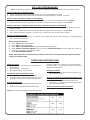
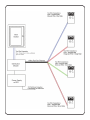
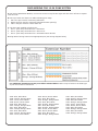
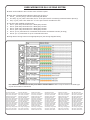
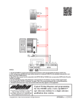
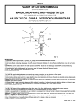
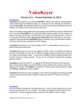
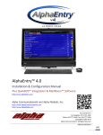
2400 Series (v2)
User Manual & Installation Instructions
AWD189
Rev 2
08/2017
ITEMS INCLUDED
•
•
•
1- Base Station
1- Distribution Module
1- Wiring Harness
INSTALLATION INSTRUCTIONS
1. For wall mount units install cabinet in desired location. For desk mount install stand (included) on back of
unit
2. Mount the Distribution Module and power supply with battery backup in an approved location.
3. Take one end of the Distribution Module Power Cable and plug it into the DC Adapter Port on the Distribution Module and the other end into the AlphaRefuge™ model PWRAPC (12-36 zone) or model PWRAPC112
(56- 112 zone) power supply with battery backup.
4. If 12-36 Zone Remove screws on back of unit and take cover off to expose internal ports.
5. Connecting Command Center to Distribution Module
A. The Command Center connects to Card 1 of the Distribution Module. (*Note: The maximum cable
length to Command Center is 6200’ for 22 GA cable and 3900’ for 24 GA cable.)
B. If Command Center includes auxillary Button Console, or Secondary Station connect to the Distribution Module per the following:
i. Button Console 1 or Secondary Station (12-16 Zone): (See pages 4 & 5)
ii. Button Console 2 and/or a Secondary Station (28-112 Zone) with Button Consoles(s): Locate
additional DKP port(s) on additional card and wire out with appropriate pair for extenstion on port.
6. Connecting Call Boxes to the Distribution Module
A. Call Boxes connect to the Distribution Module via the included wiring harnesses.
B. Plug the RJ45 connectors of the wiring harness into the ports of the Module following
C. Wire the Locations to single pair 24 or 22 gauge UTP cable, following EIA/TIA Standards. the Diagrams on Pages 4-5.
D. Connect the cabling to the Distribution Module (Note: The maximum cable length to Call Boxes is
112,500’ for 22 GA cable and 70,300’ for 24 GA cable.)
7. Turn on AlphaRefuge™ Power Supply
8. Power On the Distribution Module
DISTRIBUTION MODULE
PROGRAMMING
Note: All programming for the Distribution Module will
be done from the Command Center Handset.
Programming Time Zone
1. Enter programming mode
• Dial 1#91
• Enter Password: 7284
2. Dial 1002 (time zone code)
• Eastern 111
• Central 112
• Mountain 113
• Pacific 114
3. Touch Check Mark Button in middle of Command
Center Phone.
4. Exit programming – Dial 00 - Touch Check Mark
Button
Programming Month – Day – Year
1. Enter programming mode
• Dial 1#91
• Enter Password: 7284
2. Dial 1001 (Month – Day- Year)
• Example: 1001 04152014 (April 15 2014)
3. Touch Check Mark Button
4. Exit Programming – Dial 00 - Touch Check Mark Button
Programming Time
1. Enter programming mode
• Dial 1#91
• Enter Password: 7284
2. Dial 1003 (Hours – Min – Sec)
• Example: 1003 143000 (2:30 p.m.)
3. Touch Check Mark Button
4. Exit Programming Dial 00 - Touch Check Mark Button
Alpha Communications • 42 Central Drive • Farmingdale NY 11735-1202
Toll-Free Technical Line 1-800-666-4800 • Phone: (631) 777-5500 • Fax: (631) 777-5599
Web: www.alphacommunications.com •
Email: [email protected]
Due to continuous product improvement, all colors, sizes, wiring and specifications are subject to change without notice.
©Copyright 2014 Alpha Communication®. All Rights Reserved.
CALL BOX PROGRAMMING
Note: Connect the Call Box to an active Port on Distribution Module and follow the instructions below
Call Box Calls the Command Center
1. For the Call Box to call the Command Center, it must be programmed to dial 0
2. Follow the directions that came with the Call Box to program Memory Location 1 to dial 0
Call Box Calls a Number Outside of the Building
1. For the Call Box to call a number outside the building, it must be programmed to first dial 3931
2. Follow the directions that came with the Call Box to program Memory Location 1 to dial 3931
Call Box Calls the Command Center First then a Number Outside of the Building
1. The Call Box can be programmed to call the Command Center first and if that call is not answered, call an
outside number.
2. Follow the directions that came with the Call Box to program Memory Location 1 to dial 3931
3. Then program Memory Location 2 to dial 9, Pause, Pause then the outside phone number.
Call Box Location Message
1. Set Message Frequency to option “3”. Record your message. At the end of the message, say “Top Stop Playback, Press The Pound Key”
At
1.
2.
3.
4.
the Command Center:
Press 1#91 (Enters Admin Mode)
Press 7284 (Admin Password)
Press 25011, Checkmark Button (Enters Message Programming)
Press 250201, Checkmark Button, wait 5 seconds, Checkmark Button (records dead air in place of
emergency message on Distribution Mode)
5. Press 00, Checkmark Button.
NOTE: The silence is to avoid message conflicts. If sound is recorded it will be heard along with
locally recorded mesage.
OPERATING INSTRUCTIONS
Indicator Status
1. Red LED Light – Incoming call or connected to
Ouside Party
2. Blue LED Light – Active Call
3. Blue LED Flashing – Call on Hold
Answering Call at Command Center
1. Lift Handset to answer first incoming call.
2. If multiple calls, press Red LED Light of next desired call (this will place original call On Hold)
Disconnecting Calls
1. Select the desired Flashing Blue LED and press
*, #
2. Each call must be disconnected individually.
Note: If you hang up handset before disconnecting
each call, LED(s) will remain lit. Lift Handset press
lit LED, 5, then *, # to disconnect, hang up handset.
Repeat for each lit LED.
Calling a Location
1. Pick up Handset and press desired Location key
(Blue LED will light)
Joining an Existing Conversation between Location & Outside Party
1. Pick up Handset and press Red LED, then 5
2. You will be in a 3-way conversation with the Outside Party and Location
Call the Last Phone that Dialed Out
1. Pick up the Handset and Dial 1092
CARD WIRING FOR 12-36 ZONE SYSTEM
A. On back of Distribution Module, remove two screws in top left and right and slide cover off unit to expose
internal cards
B.
1.
2.
3.
On top of each card there is a table indicating port usage.
SLT is the port used for connecting Call Boxes
DKP is the port used for connecting Command Center phone(s)
TWT is the port used for outside telco line
C.
1.
2.
1.
The first card installed will always be:
Port 1: (S01-S04) Connection for 4 Call Boxes
Port 2: (S05-S06) Connection for 2 Telco Lines
Port 3: (S07-S08) Connection for 2 Command Center Phones
D. Plug RJ45 of wiring harness into appropriate port (See wiring diagram below)
For additional extensions on SLT ports follow scheme below. Refer to top of cards to see what type
of port and number of extentions
2005:
2006:
2007:
2008:
2009:
2010:
2011:
2012:
2013:
2014:
2015:
Blue, Blue-White
Orange, Orange-White
Green, Green-White
Brown, Brown-White
Blue, Blue-White
Orange, Orange-White
Blue, Blue-White
Orange-Orange, White
Blue, Blue-White
Orange, Orange-White
Green, Green-White
2016:
2017:
2018:
2019:
2020:
2021:
2022:
2023:
2024:
2025:
2026:
Brown, Brown-White
Blue, Blue-White
Orange, Orange-White
Blue, Blue-White
Orange, Orange-White
Blue, Blue-White
Orange, Orange-White
Green, Green-White
Brown, Brown-White
Blue, Blue-White
Orange, Orange-White
2027:
2028:
2029:
2030:
2031:
2032:
2033:
2034:
2035:
2036:
Blue, Blue-White
Orange, Orange-White
Blue, Blue-White
Orange, Orange-White
Green, Green-White
Brown, Brown-White
Blue, Blue-White
Orange, Orange-White
Blue, Blue-White
Orange, Orange-White
CARD WIRING FOR 56-112 ZONE SYSTEM
A. Each card installed in 56-112 zone units will have 6 ports.
B.
1.
2.
3.
Each slot is labeled below indicating what type of slot it is.
S01-S__ are the port(s) used for connecting Call Boxes
The TD(1-2)(3-4) with a dot under the “D” is the port used for connecting Command Center phone(s)
TD(1-2)(3-4) with a dot under the “T” is the port used for outside telco line
C.
1.
2.
3.
4.
5.
6.
The first card installed will always be:
Port 1: (S01-S04) Connection for 4 Emergency Phones
Port 2: (S05-S08) Connection for 4 Emergency Phones
Port 3: (S09-S12) Connection for 4 Emergency Phones
Port 4: (S13-S16) Connection for 4 Emergency Phones
Port 5: (D1-2) Connection for Command Center Phone and Button Console (If Using)
Port 6: (T1-2) Connection for up to 2 outside Telco Lines
D. Plug RJ45 of wiring harness into appropriate port (See wiring diagram below)
For additional extensions on SLT ports follow scheme below. Refer to top of cards to see what type
of port and number of extentions
2017: Blue, Blue-White
2018: Orange, Orange-White
2019: Green, Green-White
2020: Brown, Brown-White
2021: Blue, Blue-White
2022: Orange, Orange-White
2023: Green, Green-White
2024: Brown, Brown-White
2025: Blue, Blue-White
2026: Orange, Orange-White
2027: Green, Green-White
2028: Brown, Brown-White
2029: Blue, Blue-White
2030: Orange, Orange-White
2031: Green, Green-White
2032: Brown, Brown-White
2033: Blue, Blue-White
2034: Orange, Orange-White
2035: Green, Green-White
2036: Brown, Brown-White
2037: Blue, Blue-White
2038: Orange, Orange-White
2039: Green, Green-White
2040: Brown, Brown-White
2041: Blue, Blue-White
2042: Orange, Orange-White
2043: Green, Green-White
2044: Brown, Brown-White
2045: Blue, Blue-White
2046: Orange, Orange-White
2047: Green, Green-White
2048: Brown, Brown-White
2049: Blue, Blue-White
2050: Orange, Orange-White
2051: Green, Green-White
2052: Brown, Brown-White
2053: Blue, Blue-White
2054: Orange, Orange-White
2055: Green, Green-White
2056: Brown, Brown-White
2057: Blue, Blue-White
2058: Orange, Orange-White
2059: Green, Green-White
2060: Brown, Brown-White
2061: Blue, Blue-White
2062: Orange, Orange-White
2063: Green, Green-White
2064: Brown, Brown-White
2065: Blue, Blue-White
2066: Orange, Orange-White
2067: Green, Green-White
2068: Brown, Brown-White
2069: Blue, Blue-White
2070: Orange, Orange-White
2071: Green, Green-White
2072: Brown, Brown-White
2073: Blue, Blue-White
2074: Orange, Orange-White
2075: Green, Green-White
2076: Brown, Brown-White
2077: Blue, Blue-White
2078: Orange, Orange-White
2079: Green, Green-White
2080: Brown, Brown-White
2081: Blue, Blue-White
2082: Orange, Orange-White
2083: Green, Green-White
2084: Brown, Brown-White
2085: Blue, Blue-White
2086: Orange, Orange-White
2087: Green, Green-White
2088: Brown, Brown-White
2089: Blue, Blue-White
2090: Orange, Orange-White
2091: Green, Green-White
2092: Brown, Brown-White
2093: Blue, Blue-White
2094: Orange, Orange-White
2095: Green, Green-White
2096: Brown, Brown-White