1
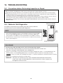
10. TROUBLESHOOTING
10-1. Precautions before Performing Inspection or Repair
After checking the self-diagnostics monitor, turn the power OFF before starting inspection or repair.
High-capacity electrolytic capacitors are used inside the outdoor unit controller (inverter).They retain an electrical charge
(charging voltage DC 310 V) even after the power is turned OFF, and some time is required for the charge to dissipate. Be
careful not to touch any electrified parts before the controller LED (red) turns OFF.
If the outdoor controller is normal, approximately 30 seconds will be required for the charge to dissipate. However, allow at
least 5 minutes for the charge to dissipate if there is thought to be any trouble with the outdoor controller.
After repairs are carried out, be sure to press and hold the TEST RUN button until the buzzer sounds 2 times to erase the
diagnosis results.
Main unit controller
10-2. Method of Self-Diagnostics
If the indoor unit operation lamp is blinking every 0.5 seconds, follow the
procedure below to perform detailed trouble diagnostics.
NOTE
TEST
RUN
button
1. If the operation lamp blinks every 0.5 seconds immediately when the power is turned ON,
there is an external ROM (OTP data) failure on the indoor circuit board or ROM socket
insertion problem, or the ROM has not been installed. Make sure the ROM is in existence.
2. The failure mode is stored in memory even when the power is not ON. Follow the procedure
below to perform diagnostics.
ON/OFF operation button
PROCEDURE
1. Turn the power supply switch ON. However, the A/C itself should remain stopped.
2. Press and hold the TEST RUN button on the main unit controller until the buzzer sounds 1 time.
At this time, releasing the TEST RUN button starts self-diagnostics.
3. If there is a sensor failure or a protective function has activated, self-diagnostics lamps 1, 2, and 3 will illuminate in the
following pattern: 5 seconds blinking (illuminated) + 2 seconds OFF. (Buzzer sounds once while lamps are OFF.)
NOTE
If there is no trouble, then self-diagnostics lamps 1, 2, and 3 do not illuminate, and the buzzer does not sound.
4. Diagnostics is completed when the buzzer sounds 3 times.
< IMPORTANT> After repairs are carried out, be sure to press and hold the TEST RUN button until the buzzer
sounds 2 times. When the TEST RUN button is released, the buzzer sounds 1 long beep, and
the diagnosis results are erased.
43
(1) Self-diagnostics Lamps
(3)
ION
lamp
(2)
TIMER
lamp
(1)
OPERATION
lamp
If there is no trouble, the lamps neither blink nor illuminate.
Since the indications cover various units, the corresponding parts listed below may not be present in some models.
.... OFF
Indication on indoor unit
Ion
Timer
Operation
(3)
(2)
(1)
Code
Diagnostics item
S01
Room temperature sensor failure
S02
Indoor heat exchanger sensor failure
S03
Humidity sensor failure
S04
NOTE
.... Blinking
.... Illuminated
Diagnostics contents
(1) Sensor open circuit or short circuit
(2) Contact failure at connector or open circuit at terminal crimping location (short-circuit
detection only for the humidity sensor)
Compressor temperature sensor failure
SH(Suction) sensor failure
S05
Outdoor heat exchanger sensor failure
S06
Outdoor air temperature sensor failure
S07
Electrical current detection failure
(1) Operating frequency is 45 Hz or higher and less than 0.5 A of current is flowing.
E01
Indoor/outdoor communications failure
(serial communications)
(1) Miswiring (2) AC power failure (3) Blown fuse (4) Power relay failure
(5) Indoor or outdoor circuit board failure
E02
HIC circuit failure
(1) HIC or power Tr failure (2) Outdoor fan does not turn. (3) Instantaneous power outage
(4) Service valve not opened. (5) Outdoor fan blocked. (6) Continuous overload operation
(7) Compressor failure (8) Outdoor circuit board failure
E03
Outdoor unit external ROM failure
(1) External ROM data failure (2) External ROM installation failure
E04
Peak current cut-off
(1) Operating current is 20 A or higher.
E05
PAM circuit failure
(1) PAM circuit abnormal voltage
E06
Compressor discharge overheat
prevention activated.
(1) Electric expansion valve failure (2) Capillaries choked (3) Shortage of refrigerant
(2) Protection for current
(1) Locked fan motor (2) Contact failure at connector
(3) Noise, instantaneous power blackout, or power waveform error due to lightning or other factor
E07
Indoor fan operating failure
Indoor zero-cross failure
E08
4-way valve switching failure
(1) 4-way valve failure (heat pump model only)
(2) Indoor heat exchanger temperature sensor disconnected.
E09
No-refrigerant protection
(1) Service valve not opened. (2) Shortage of refrigerant
E10
DC compressor drive circuit failure
(1) Open phase (2) Outdoor circuit board failure
E11
Outdoor fan operating failure
(1) Contact failure at connector
E12
Outdoor system communications failure
(1) Miswiring in inter-unit
E13
Freeze-prevention operation activated.
(1) Indoor fan system failure (2) Shortage of refrigerant (3) Low-temperature operation
(2) Outdoor circuit board failure
(2) Outdoor circuit board failure
If the operation lamp (orange) continues to blink immediately after when the power source has been supplied
to the air conditioner, there might be trouble with the external ROM (E14) in the indoor unit.
44