1
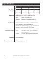
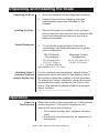
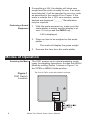
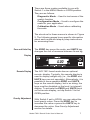
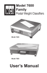
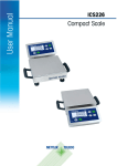
Model 7821
Bench Scale
User’s Manual
UNITED STATES
This equipment has been tested and found to comply with the
limits for a Class A digital device, pursuant to Part 15 of the FCC
Rules. These limits are designed to provide reasonable protection
against harmful interference when the equipment is operated in a
commercial environment. This equipment generates, uses, and
can radiate radio frequency energy and, if not installed and used
in accordance with the instruction manual, may cause harmful
interference to radio communications. Operation of this equipment in a residential area is likely to cause harmful interference in
which case the user will be required to correct the interference at
his own expense.
CANADA
This digital apparatus does not exceed the Class A limits for radio
noise emissions from digital apparatus set out in the radio Interference Regulations of the Canadian Department of Communications. Le present appareil numerique n’emet pas de bruits
radioelectroniques depassant les limites applicables aux appareils
numeriques de la Class A prescrites dans le Reglement sur le
brouillage radioelectrique que edicte par le ministre des Communications du Canada
CAUTION
Risk of electrical shock. Do not remove cover. No user
serviceable parts inside. Refer servicing to qualified
service personnel.
Weigh-Tronix reserves the right to change
specifications at any time.
11/19/02 PN 7424-15813E e1
2
Model 7821 Bench Scale User’s Manual
Table of Contents
Table of Contents ..................................................... 3
Specifications ........................................................... 4
Unpacking and Installing the Scale .......................... 5
Operation ................................................................. 5
Power Up ................................................................. 5
Modes of Operation ................................................. 6
Diagnostics Mode ................................................... 10
Configuration Mode ................................................ 14
Calibration Mode .................................................... 16
Gravity Mode .......................................................... 18
Error Codes ............................................................ 19
Communication ...................................................... 19
Troubleshooting ..................................................... 22
Spare Parts List...................................................... 23
Model 7821 Bench Scale User’s Manual
3
Specifications
Model
7821-70
Capacity and
Resolution
7821-75
7821-100
Approvals
Zero Window
#Capacity (lb)
150 x .05 lb
150 x .02 lb
200 x .05 lb
Capacity (kg)
60 x .02 kg
70 x .02 kg
75 x .02 kg
75 x .01 kg
100 x .02 kg
Divisions
3000d
3500d
3750d
7500d
4000d
5000d
Model 7821-70, 7821-75 and 7821-100
USA:
NTEP COC #95-070
Canada:
Ministry of Industry #AM5076
Initial automatic zero setting is ±10% of maximum capacity—active at power up.
Manual zero setting range is ± 2% of maximum
capacity—active using the ZERO key.
Transformer Voltage
Frequency
Power Requirements
4
Input:
120 VAC +10%, -15% Standard 3
wire w/ground
Output:
15 VDC @.3 Amps DC minimum
60 Hz Standard
0.1 Amp maximum
Model 7821 Bench Scale User’s Manual
Unpacking and Installing the Scale
Unpacking the Scale
1. Remove contents of the shipping container.
2. Inspect the scale for shipping damage.
Immediately report any damage to the
shipper.
Installing the Scale
Cutout Dimensions
Attaching Velcro™
Fasteners (Optional
remote display only)
1. Mount the scale on a stable, level surface
that is free from air currents and vibration. Be
sure the scale platter does not touch any
adjacent surfaces.
2. To install the scale surface flush with a
countertop, use these dimensions to guide
your construction:
7821 Platform
Dimensions
Minimum Cutout
Dimensions
14" (35.6cm) W x
12.5" (31.7cm) L
4.1" (10.4cm) Min Ht.
adjustable to 4.6" (11.7cm)
14.75" (37.5cm) W x
13.25" (33.7cm) L
For the optional remote display, attach Velcro™
fasteners to both the back of the display and to
the surface where the display is to be mounted.
To attach the Velcro fasteners, clean the mounting areas thoroughly and press the Velcro into
place. The adhesive adheres best to a smooth,
clean surface.
Velcro is a registered trademark of Velcro USA, Inc.
Operation
Power Up
Test Sequence
When the scale is first powered up, it will perform
a test sequence. During this sequence, the
display will show the following:
• The model number and software revision
level
• A numeric counting test for all segments of
the display
Model 7821 Bench Scale User’s Manual
5
If everything is OK, the display will show zero
weight and the scale is ready for use. If an error
was detected, it will be reported by an error code
as described in the section Error Codes. If the
scale is outside the ± 10% zero window, center
dashes are displayed “_ _ _ _.” Recalibration
may be required.
Performing a Normal
Weighment
1. With the scale powered on, make sure the
scale platter is empty and the display is at
zero. If it not, press the ZERO key…
0.00 is displayed.
2. Place an item to be weighed on the scale
platter…
The scale will display the gross weight.
3. Remove the item from the scale platter.
Modes of Operation
Accessing the Menu
Figure 1
7821 Switch
Location
6
The 7821 powers up in normal weighing mode
ready for weighing operations. Access the MENU
Mode by setting Switch 1 shown in Figure 1 to
the OPEN or MENU Mode position.
Top view of 7821 scale with platter removed.
Model 7821 Bench Scale User’s Manual
There are three modes available to you with
Switch 1 in the MENU Mode or OPEN position.
They are as follows:
Diagnostic Mode – Used to test areas of the
scale’s function
Configuration Mode – Used to configure the
scale for your application
Calibration Mode – Used when calibrating
the scale
The structure for these menus is shown in Figure
2. The following pages have specific information
about each mode and step-by-step instructions
for accessing them.
Zero and Units Key
The ZERO key zeros the scale, and UNITS key
changes the unit of measure between lb and kg.
Display
Remote Display
Gravity Adjustment
The NCI 7821 bench scale has an optional
remote display. Typically, the remote display is
used to display weight only (i.e., the ZERO and
UNITS keys are not operable). Alternatively, it is
possible to have operable ZERO and UNITS
keys on the remote display, but in so doing, the
keys must be disabled on the local (or internal)
display. To activate the ZERO and UNITS keys
on the remote display, set dip Switch 3 to the
OPEN position.
With Switch 2 set to OPEN, you can adjust the
local gravity value. Press the ZERO key to
increase the value or press the UNITS key to
decrease the value. See Gravity Adjustment
section for details.
Model 7821 Bench Scale User’s Manual
7
Figure 2
Menu Structure
8
Model 7821 Bench Scale User’s Manual
The NCI 7821 bench scale allows calibration of
the scale using less than full capacity weights.
The following tables show alternative weights that
can be used to calibrate the scale at its designated capacity. See Table 1 for alternate calibration span loads.
Alternative Calibration
Span Points
Table 1:
Alternative Calibration Span Points
Alternative
Capacity
Calibration
(lbs)
Weights (lbs)
150 x .05 lb 10, 50, 150
150 x .02 lb 10, 50, 150
Alternative
Capacity
Calibration
(kg)
Weights (kg)
60 x .02 kg
10, 30, 60
70 x .02 kg
10, 30, 70
75 x .02 kg
10, 30, 75
75 x .01 kg
10, 30, 75
200 x .05 lb 10, 100, 200 100 x .02 kg 10, 50, 100
Baud Rate and
Parity Options
Table 2:
Baud Rate and Parity Options
Display
12 E
48 E
*96 E
192 E
12 o
48 o
96 o
192 o
12 n
48 n
96 n
192 n
Baud
1200
4800
9600
19,200
1200
4800
9600
19,200
1200
4800
9600
19,200
Parity
Even
Even
Even
Even
Odd
Odd
Odd
Odd
None
None
None
None
*Factory Default Setting
Model 7821 Bench Scale User’s Manual
9
Scale lb/kg
Capacity and
Count-by Choices
Table 3:
Scale lb/kg Capacity and Count-by Choices
150 - 1
150 - 2
150 - 3
150 - 4
200
Capacity (lb)
150 x .05
150 x .05
150 x .05
150 x .02
200 x .05
Capacity (kg)
60 x .02
70 x .02
75 x .02
75 x .01
100 x .02
Diagnostics Mode
The Diagnostic (DIAG) Mode menu lets you test
specific areas of the scale’s function. These
areas are:
Display (DISP) – Shows the version and
revision of the software, followed by a display
segment test.
RAM (RA) – Performs a nondestructive test
of RAM in the processor. Displays PASS or
FAIL.
ROM (RO) – Performs a checksum of all
locations of ROM in the processor. Displays
PASS or FAIL.
Input/Output (I/O) – Data is output by the scale,
and through the use of a loopback connector, the
data is immediately read back into the receive
channel and verified against what was sent.
PASS or FAIL is displayed. Requires a jumper
(short) between transmit and receive data lines.
Division, Test w/AZT (HRESA) – Weight data is
normalized to 100,000 counts of displayed
resolution. AZT is enabled. Typically used by
service technicians.
Division, Test w/o AZT (HRESN) – Weight data
is normalized to 100,000 counts of displayed
resolution. AZT is disabled. Typically used by
service technicians.
10
Model 7821 Bench Scale User’s Manual
Step-by-Step
Instructions for
DIAG Mode
Follow these steps to access the tests in the
DIAG menu.
1. From normal weighing mode, move Switch 1
to the MENU Mode or OPEN position. (See
Figure 1).
Display shows DIAG.
Press the ZERO key to
scroll through lists of
selections.
Press the UNITS key
to make a selection.
2. Press the UNITS key…
DISP is displayed. This stands for
display.
3. Press the UNITS key to perform the display
test described earlier…
If you want to skip a
test, press the ZERO
key to scroll to the
next test.
Display test is performed and the display
shows DISP after the test is completed.
DIAG will flash every
10 seconds during the
high resolution test to
remind you that you
are doing a test and
not seeing normal
weight readings.
4. Press the ZERO key…
RA is displayed. This stands for the RAM
test.
5. Press the UNITS key to perform the RAM
test…
PASS or FAIL is displayed briefly, then
DISP. If the test fails, contact your local
Weigh-Tronix distributor for service.
6. Press the ZERO key to scroll to the ROM
test…
RO is displayed. This stands for the
ROM test.
Model 7821 Bench Scale User’s Manual
11
7. Press the UNITS key to perform the ROM
test…
PASS or FAIL is displayed. If the test
fails, contact your local Weigh-Tronix
distributor for service.
8. Press the ZERO key to scroll to the I/O
test…
I/O is displayed. This stands for the
Input/Output test.
9. With a loopback connector in place, press
the UNITS key to perform the I/O test…
PASS or FAIL is displayed. If the test
fails, check your connections and/or
contact your local Weigh-Tronix distributor for service.
10. Press the ZERO key…
HRESA is displayed. This stands for the
high resolution test with AZT enabled.
11. Press the UNITS key to perform this test…
The display shows the weight on the
scale at a resolution of 100,000 counts.
12. Press the UNITS key to stop the test…
HRESA is displayed.
13. Press the ZERO key…
HRESN is displayed. This stands for the
high resolution test without AZT enabled.
14. Press the UNITS key to perform this test…
The display shows the weight on the
scale at a resolution of 100,000 counts.
15. Press UNITS key to stop the test…
HRESN is displayed.
12
Model 7821 Bench Scale User’s Manual
16. Press the ZERO key. . .
LOC-G is displayed. This stands for local
gravity or current gravity setting.
17. Press the UNITS key. . .
The local or current gravity setting is
displayed.
18. Press the ZERO key. . .
CAL-G is displayed. This stands for
calibration gravity setting.
19. Press the UNITS key. . .
The calibration gravity setting is displayed.
20. When you are finished, press the ZERO key,
which displays DONE, and press the UNITS
key, DIAG is displayed, or place Switch 1
back to the closed position to return back to
normal weighing mode.
Model 7821 Bench Scale User’s Manual
13
Configuration Mode
The Configuration (CONF) Mode menu allows
configuration of the scale to the specific application need. The items you can configure are as
follows:
Filtering (FILT) – Choose between FAST
and SLO filtering. Slow should be chosen in
areas susceptible to vibration. Choose FAST
filtering for more stable conditions.
Baud (BAUD) – Choose a baud and parity
from table.
Protocol (PROT) – Choose serial communication protocol:
NCI - Ref. 8408-14788-01 (W, S, Z, H, U, M
Only)
8213 - Ref. 8408-14788-03
3835 - Ref. 8408-14788-12
Step-by-Step
Instructions for
CONF Mode
Follow these steps to access and configure the
items in the CONF menu. Refer to Figure 2.
1. From the normal weighing mode, move
Switch 1 to Menu Mode or OPEN position,
then press the ZERO key repeatedly until…
CONF is displayed.
2. Press the UNITS key…
FILT is displayed. This stands for filtering.
3. Press the UNITS key…
The current setting, FAST or SLO, is
displayed.
14
Model 7821 Bench Scale User’s Manual
10
4. Use the ZERO key to toggle between the two
choices. Press the UNITS key when the
choice you want is displayed…
The choice is accepted and the display
shows FILT.
5. Press the ZERO key…
BAUD is displayed.
6. Press the UNITS key…
The current baud and parity choice is
displayed.
7. Use the ZERO key to scroll the choices
found in Table 2. When the choice you want
is displayed, press the UNITS key…
The choice is accepted and the display
shows BAUD.
8. Press the ZERO key…
PROT is displayed.
9. Press the UNITS Key…
The current protocol is displayed.
10. Use the ZERO key to scroll between the
three protocol choices. When the protocol
you want is displayed, press the UNITS
key…
The choice is accepted and the display
shows PROT.
11. When finished configuring the scale, press
the ZERO key, which displays DONE, then
press the UNITS key, DIAG is displayed, or
place Switch 1 back to the closed position to
return back to normal weighing mode.
11
Model 7821 Bench Scale User’s Manual
15
Calibration Mode
The Calibration (CAL) Mode menu allows scale
calibration. The items in the Calibration menu are
as follows:
Pounds/Kilograms (lb or 1000G) – Selects
the unit of measure of your calibration test
weights.
Scale or Class – When calibrating the scale
for lb, calibrate the unit as a SCALE or as a
CLASS (weight classifier/postal rounding).
U On / U Off – When configured for U ON,
the scale will allow switching between lb/kg
using the UNITS key.
Capacity (100, etc.) – Selects the capacity of
the scale.
Follow these steps to calibrate the scale. Refer to
Figure 2.
Step-by-Step
Instructions for
CAL Mode
1. From normal weighing mode, move Switch 1
to the Menu Mode or OPEN position…
DIAG is displayed. Press the ZERO key
until CAL is displayed.
2. Press the UNITS key to start calibration…
LBS or 1000G (kg) is displayed.
Warning!
Entering this mode can
erase the calibration
already saved. Special
calibration weights are
needed to use
calibration mode.
16
3. Press the ZERO key to toggle between the
choices of unit of measure (lb or kg). When
the choice you want is displayed, press the
UNITS key to accept…
The choice is accepted and U ON is
displayed.
Model 7821 Bench Scale User’s Manual
12
4. Press the ZERO key to toggle between the
choices U ON or U OFF. Once your choice is
displayed, press the UNITS key. See above
for the definitions of calibrating the scale
using U ON or U OFF.
5. If LB was chosen for calibration, the scale will
display SCALE. Press the ZERO key to
toggle between SCALE and CLASS. Press
the TEST key. If kg was chosen, this step is
skipped. The scale then prompts one of the
capacities from Table 3.
6. Press the ZERO key to toggle between the
capacity choices. When the choice you want
is displayed, press the UNITS key…
The scale prompts LOAD 0.
7. Clear all weight from the scale platter and
press the UNITS key…
After a brief pause, LOAD xxx is displayed (xxx = Span Weight).
Alternate calibration points can be
chosen using the TEST key to toggle
between choices (see Table 1).
If no span weight is
applied, calibration will
be aborted. “CAL
ERROR ABORT” will
be displayed.
8. Place chosen span calibration weight on the
scale and press the UNITS key…
After a brief pause, DONE is displayed.
The scale then prompts DIAG.
9. Remove all calibration weights from scale.
10. Return Switch 1 to the closed position…
The scale returns to normal weighing
mode.
The scale is now tested, configured and calibrated. It is ready for use in your application.
Model 7821 Bench Scale User’s Manual
17
Gravity Mode
The Gravity Mode feature provides a means of
adjusting the scale’s internal calibration factors to
compensate for variations in acceleration due to
gravity at different geographic locations. These
differences can cause a given mass to indicate a
slightly different weight at an end-user’s (local)
site than it did at the Calibration (CAL) site.
To make the adjustment, you must know the
value of the gravity constant for the local site.
This value is expressed in meters per second,
per second (i.e., m/s2). It is not necessary to
calibrate the scale, therefore, no calibration
weights are needed to make this adjustment.
Warning: Using this
feature in “sealed”
applications may be
subject to approval by
the appropriate
governing agency
at the end-users site.
Gravity value roles
‘over’ at 9.8400 and
rolls ‘under’ at 9.7700.
The scale maintains two gravity setting values.
The first is the “calibration-site” value known as
CAL-G. The second is the end-user or “local-site”
value and is known as LOC-G. When the scale
was originally calibrated at the factory, the CAL-G
and LOC-G values were both set to 9.8040 which
is the gravity constant for the manufacturing site.
To adjust the displayed weight value to accurately reflect an applied test weight, you can
either recalibrate the scale or adjust the local
gravity setting.
To view the calibration or local gravity values, you
must access the DIAG menu and scroll to LOC-G
or CAL-G message and press the UNITS key.
To view or adjust the Local Gravity value, set
Switch 2 to the OPEN position. The display will
indicate the current “local” gravity value. Press
the ZERO key to increment the value or the
UNITS key to decrement the value. The gravity
value will change in steps of .0002. When the
correct value is displayed, return Switch 2 to the
CLOSED position. The scale will now use this
new relationship between calibration and local
gravity for its weight calculations.
18
Model 7821 Bench Scale User’s Manual
Error Codes
Any system errors detected by the scale will be
displayed as the letter E followed by a two-digit
error code. Press the UNITS key to continue
operation. If a calibration error occurs, the only
way to clear it is by recalibrating the scale.
The error codes are broken down into two
hexadecimal numbers, with each bit defining a
single error condition. The error codes are
defined as follows:
Communication
Interface Cable
The NCI 7821 scale comes factory configured
as a serial RS-232 interface device. There is one
9-pin DE type female connector accessible at the
rear of the unit. The functional pinout of this
cable is that of a standard PC which is as
follows:
Model 7821 Bench Scale User’s Manual
19
DE-9 Female Scale
Serial
Communications
Protocol
DE-9 Male Host
Pin
Name
Direction
Pin
Name
Direction
1.
2.
3.
4.
5.
6.
7.
8.
9.
JMP 1
TXD
RXD
JMP 1
SG
JMP 1
JMP 2
JMP 2
NC
OUT
IN
-
1.
2.
3.
4.
5.
6.
7.
8.
9.
DCD
RXD
TXD
DTR
GRD
DSR
RTS
CTS
RI
IN
IN
OUT
OUT
IN
OUT
IN
IN
For command/response descriptions, please
refer to the following Weigh-Tronix NCI Serial
Communications Documents:
NCI Standard Protocol: 8408-14788-01 (W, S, Z,
H, U, M only)
8213 Protocol: 8408-14788-03
NCI 3835 Protocol: 8408-14788-12
NCI
Communications
Protocol
20
This standard is used by all NCI bench scale
products.
SYMBOL KEY:
<ETX> End of text character (03/hex)
<LF>
Line feed character (0A hex)
<CR>
Carriage return character (0D hex)
<SP>
Space (20 hex)
x
Character from display including
minus sign
hh…
Two or more status bytes
uu
Unit of measure (lb, kg, oz, g, etc.
using ANSI standard abbreviations)
Model 7821 Bench Scale User’s Manual
W<CR>
Scale Response
<LF>xxxx.xxuu<CR>
<LF>hh...<CR><ETX>
Results
Returns decimal weight, units, plus scale status
S<CR>
Scale Response
<LF>hh…<CR><ETX>
Results
Returns scale status.
Z<CR>
Scale Response
<LF>hh…<CR><ETX>
Results
Scale is zeroed, returns status.
H<CR>Scale Response
<LF>xxxx.xxuu<CR>
<LR>hh...<CR><ETX>
Results
Returns decimal weight in 10x with units plus
scale status.
U<CR>
Scale Response
<LF>uu<CR><ETX>
Results
Changes unit of measure, returns new units.
M<CR>
Scale Response
<LF>xxxxxxxMM<CR>
<LF>hh...<CR><ETX>
Results
Returns normalized raw counts and count status.
All other commands
Scale Response
<LF>?<CR><ETX>
Results
Unrecognized command
Model 7821 Bench Scale User’s Manual
21
Troubleshooting
RECOMMENDED ACTION
SYMPTOM
Perform each step in sequence until the symptom is resolved. Once the symptom is resolved,
discontinue the troubleshooting steps and
continue with regular product usage.
No Display(s)
1. Check that the primary side of the cord is
plugged into the AC outlet, and the secondary side is properly connected to the power
jack on the back of the scale.
2. Replace power supply.
Missing or extra
segments on display
1. Replace display board.
Scale will not return to
zero, or incorrect weight
is displayed
1. Press the ZERO key.
2. Check for interference of weighing platform.
3. Power down, then power up the scale.
4. Recalibrate the scale.
Display shows
unrecognized
characters
1. Power down, then power up the scale.
2. Check software PROM for proper insertion.
3. Check display cables for the proper connection.
Display shows under
“ – – – – ” dashes
(indicates the scale is
below zero or under
capacity).
1. Verify that the weigh platter is on the scale.
2. Verify that nothing is interfering with or
rubbing against the weighing surface.
3. Press the ZERO key
4. Power down, then power up the scale.
5. Recalibrate the scale.
22
Model 7821 Bench Scale User’s Manual
Display shows center
“ – – – – ” dashes
(indicates the scale is
outside zero capacity of
±2%).
1. Verify that the weigh platter is on the scale.
2. Press the ZERO key.
3. Power down, then power up the scale.
4. Recalibrate the scale.
1. Remove all weight from the scale.
Display shows upper
“ – – – – ” dashes
(indicates the scale is
over capacity).
2. Press the ZERO key.
3. Power down, then power up the scale.
4. Recalibrate the scale.
Scale is not
transmitting data to the
host device
1. Check cable connection at both the rear of
the scale and the host device.
2. Check communication setting and baud rate
on both scale and host device.
3. Perform I/O loopback test.
4. Replace main PCB.
The ZERO key and TEST
key do not function.
1. Replace display panel.
2. Replace display PCB.
3. Replace main PCB.
Spare Parts List
Description
Keyboard Panel
Display PCB
Loadcell (100kg)
Main PCB
Power Supply
RS-232 Cable
Part Number
1163-15803
7405-15465
7154-16335-100
7405-14704-2
1148-15536
1140-13842
Model 7821 Bench Scale User’s Manual
23
Notes
24
Model 7821 Bench Scale User’s Manual
Notes
Model 7821 Bench Scale User’s Manual
25
26
Model 7821 Bench Scale User’s Manual
Model 7821 Bench Scale User’s Manual
27
1000 Armstrong Drive
Fairmont, MN 56031
Telephone: 507-238-4461
Facsimile: 507-238-4195
E-Mail: [email protected]
www.wt-nci.com