1
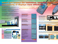
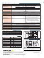
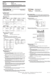
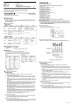
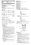
Main Specifications [Tester Specifications]
Model
3298 02 (tester) + 3298 11 (sensor)
3298 02 (tester) + 3298 21 (sensor)
Black and white
Color
Sensor type
Optical system
Enclosed cylinder type (minimum optical bore diameter: 10 mm; viewing angle: approximately. 30°)
Photodetector unit
Silicon photodiode
Measurement field of view
Distance to specimen
Visual bore in measurement
In contact
10 mm
Luminance measurement range
10 mm
19 mm
20 mm
25 mm
50 mm
42 mm
100 mm
73 mm
0.01 to 40,000 cd/m2
40.00/400.0/4,000/40,000 cd/m2
Luminance measurement range settings
Luminance measurement precision
400.0/4,000/40,000 cd/m2
±4% of indicated value + ±0.035% of full-scale value (at 23 ± 3°C,
±4% of indicated value + ±0.035% of full-scale value (at 23 ± 3°C,
70% RH or less, with type A standard light source, when the indication 70% RH or less, with type A standard light source, when the indication
2 of the set range's full-scale value)
is at least 2% and 2 cd/m
is at least 2% of the set range's full-scale value)
Flicker measurement range settings
2%/4%/8%/20% rms
±1% (Reference value; For sine wave of 200 cd/m2, 10% rms and 30 Hz at 23 ± 3°C, 70% RH or less)
Flicker measurement precision
Flicker measurement luminance range
Flicker measurement filter
5 to 40,000 cd/m2
(for sine wave of 10% rms and 30 Hz at 23 ± 3°C, 70% RH or less)
25 to 40,000 cd/m2
(for sine wave of 10% rms and 30 Hz at 23 ± 3°C, 70% RH or less)
Programmable low-pass filter, flicker base frequency can be selected from among 20, 30, 40, 50, 60, 70, 80 or 90 Hz
Approximates CIE 1931 standard spectral luminous efficiency response
Approximates CIE 1931 color matching functions
Spectral responsivity
Color system
–
Chromaticity coordinates: (x, y, L) or (u', v', L)
Tristimulus values: (X, Y, Z) or (R, G, B) or (RGB ratio)
Correlated color temperatures: (Tc, duv, L)
–
• ±0.002 or less, for type A standard light source (at 23 ± 3°C,
70% RH or less, and luminance of at least 2% of the set range's
full-scale value)
• ±0.03 or less, for combination of type A standard light
source/three-wavelength fluorescent lamp + color filters (at 23 ±
3°C, 70% RH or less, and luminance of at least 1% of the set
range's full-scale value)
Chromaticity precision
(deviation in x and y values)
User-defined luminance calibration coefficients
Linear correction of measured luminance values
–
User-defined color calibration coefficients
–
6 colors × 10 displays; XYZ measured values and entered values
Data memory
Up to 200 data for each measured item
Input
Trigger input (contact)
Output
Monitor output (0 to 2 V), DC luminance output (0 to 2 V), GO/NO-GO output (open collector)
Communication port
RS-232 (9,600 to 38,400 bps)
Operating temperature and humidity range
5 to 40°C, 70% RH or less
Sensor dimensions: approx. 67 (W) × 150 (H) ×40 (D) mm; tester dimensions: approximately. 107 (W) × 176 (H) × 55 (D) mm; weight: approximately. 1 kg
Dimensions and weight
128 ×128-pixel dot matrix LCD
Display
Power supply
Four AA batteries or optional AC adapter
Battery life
Approximately. 6 hours (for the alkaline batteries provided)
Model and Suffix Codes
Model
Suffix Code
Block Diagram
Specification
Silicon photodiode
I/V amp.
Optical filter
X
Amp.
Diffuser
Amp.
Multimedia display tester* with 1.5 meter long extension cable
329802
Language
-E
English display and user's manual
Y
-J
Japanese display and user's manual
Light
Black and white sensor, with rubber bumper
329821
Color sensor, with rubber bumper
LPF
Amp.
Distributor
lens
Monitor
output
Variable
low-pass
filter
* Excluding an AC adapter; order the proper adapter with the correct input voltage separately if necessary.
A/D
converter
LPF
Z
Multiplexer
329811
Display
(LCD)
LPF
DC luminance
output
GO/NOGO
CPU
RS-232
Trigger input
Flash
SRAM
Flicker
separator
Temperature sensor
Optional Accessories and Software
EEPROM
Product
AC adapter
Part Number
Specification
A1020UP
100 V AC adapter
A1022UP
120 V AC Adapter
Photodetector unit
B9108WB
220-240 V AC Adapter
Sensor cable
B8300LA
1.5 m long
Sensor cable
B8300LB
3.0 m long
Sensor cable
B8300LG
5.0 m long
RS-232 cable (for PC connection)
B8300LC
For 9-pin D-Sub connector on PC
RS-232 cable (for PC connection)
B8300LD
For 25-pin D-Sub connector on PC
Carrying case
329891
Case for storing tester
Recorder output plugs
B8300LJ
Four plugs
Rubber Bumper
B8300LH
Product
Light measurement data
management software
Part Number Suffix Code
Gain, color calibration
coefficients
Operation unit
Power
supply
unit
External power
supply input
Main unit
Dimensions
Unit: mm
● Luminance, contrast, flicker and chromaticity measurements
● Digital and bar graph indications
● Shading cylinder type optical system
● Luminance measurement range of 0.01 to 40,000 cd/m2
● Memory for measured data from 200 displays
● GO/NO-GO determination functions
● User-specified color calibration coefficients
● Light source color calibration coefficients
● Easy operation
● Compact and lightweight
● Battery-driven
Specification
329831
-J
Japanese version
329831
-E
English version
NOTICE
● Before operating the product, read the user’s manual thoroughly for
proper and safe operation.
● If this product is for use with a system requiring safeguards that directly
involve personnel safety, please contact the Yokogawa sales offices.
YOKOGAWA ELECTRIC CORPORATION
Test and Measurement Business Div./Phone: (81)-55-243-0313, Fax: (81)-55-243-0396
E-mail: [email protected]
YOKOGAWA CORPORATION OF AMERICA Phone: (1)-770-253-7000, Fax: (1)-770-251-2088
YOKOGAWA EUROPE B.V.
Phone: (31)-33-4641806, Fax: (31)-33-4641807
YOKOGAWA ENGINEERING ASIA PTE. LTD Phone: (65)-62419933, Fax: (65)-62412606
Subject to change without notice.
[Ed : 03/b] Copyright ©2003
Printed in Japan, 311(YG)
www.yokogawa.com/tm/
... and subscribe to “Newswave,”
our free e-mail newsletter
MS-12E
Bulletin 3298-02E
High cost-performance
Lets you measure luminance, contrast, flicker and chromaticity all with just one device. The lowcost design greatly reduces the product's price.
Digital and bar graph indications
Measurements for adjustment or inspection work are displayed both as digital values and bar
graphs. User-specified MIN, MAX and other criteria can be entered for GO/NO-GO testing of
production line samples.
Light source color calibration coefficients
Color correction coefficients for three light source types (type A standard light source, threewavelength fluorescent lamp and CRT display) ensure accurate chromaticity measurements for
each color and light source.
Excellent PC interface
In addition to a built-in memory with capacity to store measurement data for up to 200 displays,
an RS-232 interface port included as standard equipment makes data communication and
control from a PC simple.
Easy operation with contact-free system
The shading cylinder type optical system lets you make easy measurements just by moving the
sensor within range of the specimen.
Luminance Measurement
Shading cylinder type optical system
Lets you set any measurement area
Contrast Measurement
Measures the luminance of the
“white” and “black” displays to
instantaneously calculate and
display the contrast. The calculated
contrast is compared with the userset value for GO/NO-GO testing.
Flicker Measurement
Distance to specimen
Measurement field of view diameter
In contact
10 mm
20 mm
50 mm
100 mm
10 mm
19 mm
25 mm
42 mm
73 mm
Flicker Measurement
Flicker ratio
Programmable low-pass filter
Luminance
Measures the light's average luminance
(DC) and effective flicker value (ACrms) to
calculate and display the flicker ratio
(ACrms/DC). The flicker of base
frequencies between 20 and 90 Hz can be
measured by varying the programmable
low-pass filter's cutoff frequency.
The flicker correction function enables
conversions to flicker ratios (%, dB) defined
by JEITA and VESA standards.
ACrms
DC
×100
AC
DC
Received light amount
Displays luminance as a digital
value and bar graph in a range of
0.01 to 40,000 cd/m2. User-specified
MIN, MAX and other criteria can be
entered for GO/NO-GO testing.
Flicker frequency:
Can be selected from among 20, 30, 40, 50, 60, 70, 80 or 90 Hz.
Time
10
100
Frequency (Hz)
Flicker ratio (%)= ACrms ×100
DC
Flicker ratio (dB)=10 log ACrms
DC
High-Precision Chromaticity Measurement The characteristics of the color filters in
3298F's photodetector approximate the CIE 1931 color matching functions, and the tester performs optimization
calculations to minimize error. Each sensor is calibrated with a combination of a type A standard light source/threewavelength fluorescent lamp and color filters. The optimized coefficient calculated for each light source is used to
enable high-precision color measurement.
CIE 1931
Color Matching Functions
Displays flicker ratio (ACrms/DC) as
digital values (% and dB) and a bar
graph. Useful for flicker adjustment.
3298F Chromaticity Measurement (Example)
Type A standard light source + color filters Three-wavelength fluorescent lamp + color filters
2
3298F
standard spectral luminance meter
0.80
3298F
standard spectral luminance meter
0.80
1.5
Relative responsivity
1
0.60
0.60
y
0.5
y
0.40
0.40
0.20
0.20
0
Applications
Displays
LCD modules
Backlights
Chromaticity Measurement
Automated adjustment/inspection (example)
GP-IB
Plasma displays
Electroluminescent (EL) displays
LED displays
Products
with
displays
LCD TVs, plasma TVs
LCD monitors for PCs, laptops
Mobile phones, PDAs
Car navigation systems
Video game machines
Luminance,
contrast,
flicker
and RGB levels
750
850
0.40
0.60
0.80
0.00
0.00
0.20
0.40
0.60
0.80
x
White Balance Adjustment The 3298F displays RGBL levels for differences between Rm, Gm and
Bm values (calculated from measured tristimulus values) and Rs, Gs and Bs values (calculated from the target
color temperature/luminance) in real time. Displays can be adjusted to the target color temperature/luminance by
adjusting all their RGBL values to 100%.
Measurement Example
CIE 1931
color matching functions
RGB color system
(NTSC)
2
2
1.5
1
0.5
0
450
550
650
Wavelength (mm)
750
850
1.5
1
0.5
0
-0.5
350
450
550
650
750
850
Wavelength (mm)
Conversion of tristimulus XYZ values to RGB values
Measurement Functions
0.20
x
-0.5
350
Display modes
R, G, B, RGB ratio
650
0.00
0.00
Display modes
(x, y, L), (u', v', L), (X, Y, Z), (Tc, duv, L)
White balance measurement mode
Displays the difference between the
RGBL measured values and the
target values in real time.
550
Relative responsivity
Projectors
RS-232
Interface for
adjustment
450
Wavelength (mm)
Relative responsivity
Digital still cameras, video cameras
Display signal
generator
Chromaticity measurement mode
Displays GO or NO-GO for the
measured value based on the userspecified reference color and range.
A different color calibration
coefficient can be set for up to 10
different display types and 6
reference colors, enabling more
precise chromaticity measurements
for each color in each display.
-0.5
350
Displaying difference between
target color temperature/
luminance and measured values
After adjusting RGBL
values to 100%
Main Specifications [Tester Specifications]
Model
3298 02 (tester) + 3298 11 (sensor)
3298 02 (tester) + 3298 21 (sensor)
Black and white
Color
Sensor type
Optical system
Enclosed cylinder type (minimum optical bore diameter: 10 mm; viewing angle: approximately. 30°)
Photodetector unit
Silicon photodiode
Measurement field of view
Distance to specimen
Visual bore in measurement
In contact
10 mm
Luminance measurement range
10 mm
19 mm
20 mm
25 mm
50 mm
42 mm
100 mm
73 mm
0.01 to 40,000 cd/m2
40.00/400.0/4,000/40,000 cd/m2
Luminance measurement range settings
Luminance measurement precision
400.0/4,000/40,000 cd/m2
±4% of indicated value + ±0.035% of full-scale value (at 23 ± 3°C,
±4% of indicated value + ±0.035% of full-scale value (at 23 ± 3°C,
70% RH or less, with type A standard light source, when the indication 70% RH or less, with type A standard light source, when the indication
2 of the set range's full-scale value)
is at least 2% and 2 cd/m
is at least 2% of the set range's full-scale value)
Flicker measurement range settings
2%/4%/8%/20% rms
±1% (Reference value; For sine wave of 200 cd/m2, 10% rms and 30 Hz at 23 ± 3°C, 70% RH or less)
Flicker measurement precision
Flicker measurement luminance range
Flicker measurement filter
5 to 40,000 cd/m2
(for sine wave of 10% rms and 30 Hz at 23 ± 3°C, 70% RH or less)
25 to 40,000 cd/m2
(for sine wave of 10% rms and 30 Hz at 23 ± 3°C, 70% RH or less)
Programmable low-pass filter, flicker base frequency can be selected from among 20, 30, 40, 50, 60, 70, 80 or 90 Hz
Approximates CIE 1931 standard spectral luminous efficiency response
Approximates CIE 1931 color matching functions
Spectral responsivity
Color system
–
Chromaticity coordinates: (x, y, L) or (u', v', L)
Tristimulus values: (X, Y, Z) or (R, G, B) or (RGB ratio)
Correlated color temperatures: (Tc, duv, L)
–
• ±0.002 or less, for type A standard light source (at 23 ± 3°C,
70% RH or less, and luminance of at least 2% of the set range's
full-scale value)
• ±0.03 or less, for combination of type A standard light
source/three-wavelength fluorescent lamp + color filters (at 23 ±
3°C, 70% RH or less, and luminance of at least 1% of the set
range's full-scale value)
Chromaticity precision
(deviation in x and y values)
User-defined luminance calibration coefficients
Linear correction of measured luminance values
–
User-defined color calibration coefficients
–
6 colors × 10 displays; XYZ measured values and entered values
Data memory
Up to 200 data for each measured item
Input
Trigger input (contact)
Output
Monitor output (0 to 2 V), DC luminance output (0 to 2 V), GO/NO-GO output (open collector)
Communication port
RS-232 (9,600 to 38,400 bps)
Operating temperature and humidity range
5 to 40°C, 70% RH or less
Sensor dimensions: approx. 67 (W) × 150 (H) ×40 (D) mm; tester dimensions: approximately. 107 (W) × 176 (H) × 55 (D) mm; weight: approximately. 1 kg
Dimensions and weight
128 ×128-pixel dot matrix LCD
Display
Power supply
Four AA batteries or optional AC adapter
Battery life
Approximately. 6 hours (for the alkaline batteries provided)
Model and Suffix Codes
Model
Suffix Code
Block Diagram
Specification
Silicon photodiode
I/V amp.
Optical filter
X
Amp.
Diffuser
Amp.
Multimedia display tester* with 1.5 meter long extension cable
329802
Language
-E
English display and user's manual
Y
-J
Japanese display and user's manual
Light
Black and white sensor, with rubber bumper
329821
Color sensor, with rubber bumper
LPF
Amp.
Distributor
lens
Monitor
output
Variable
low-pass
filter
* Excluding an AC adapter; order the proper adapter with the correct input voltage separately if necessary.
A/D
converter
LPF
Z
Multiplexer
329811
Display
(LCD)
LPF
DC luminance
output
GO/NOGO
CPU
RS-232
Trigger input
Flash
SRAM
Flicker
separator
Temperature sensor
Optional Accessories and Software
EEPROM
Product
Part Number
Specification
AC adapter
A1020UP
100 V AC adapter
AC adapter
A1022UP
120 V AC adapter
AC adapter
B9108WB
220-240 V AC adapter
Sensor cable
B8300LA
1.5 m long
Sensor cable
B8300LB
3.0 m long
Sensor cable
B8300LG
5.0 m long
RS-232 cable (for PC connection)
B8300LC
For 9-pin D-Sub connector on PC
RS-232 cable (for PC connection)
B8300LD
For 25-pin D-Sub connector on PC
Carrying case
329891
Case for storing tester
Recorder output plugs
B8300LJ
Four plugs
Rubber Bumper
B8300LH
Product
Light measurement data
management software
Part Number Suffix Code
Photodetector unit
Gain, color calibration
coefficients
Operation unit
Power
supply
unit
External power
supply input
Main unit
Dimensions
Unit: mm
Specification
329831
-J
Japanese version
329831
-E
English version
NOTICE
● Before operating the product, read the user’s manual thoroughly for
proper and safe operation.
● If this product is for use with a system requiring safeguards that directly
involve personnel safety, please contact the Yokogawa sales offices.
YOKOGAWA ELECTRIC CORPORATION
Test and Measurement Business Div./Phone: (81)-55-243-0313, Fax: (81)-55-243-0396
E-mail: [email protected]
YOKOGAWA CORPORATION OF AMERICA Phone: (1)-770-253-7000, Fax: (1)-770-251-2088
YOKOGAWA EUROPE B.V.
Phone: (31)-33-4641806, Fax: (31)-33-4641807
YOKOGAWA ENGINEERING ASIA PTE. LTD Phone: (65)-62419933, Fax: (65)-62412606
Subject to change without notice.
[Ed : 01/b] Copyright ©2003
Printed in Japan, 311(YG)
MS-12E