1
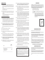
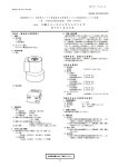
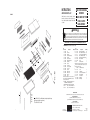
INSTRUCTIONS
AND REPAIR PARTS LIST
EXHIBIT A
9
CQB20 Brooder has a heater for brooding. CQGO20
Growout Pen is identical to CQB20 except that it has no
heater. CQB600 Caster Base is designed for either CQB20
or CQGO20.
9
15
14
! WARNING !
7
7
5
6
Be sure Power Cord Assembly is not connected during installation or cleaning. Remove heater before
cleaning. Do not touch either lug of the thermostat if power source is connected. Touch only the adjustment
knob. Do not defeat electrical ground afforded by 3-prong Cord Assembly. Model AT10 Adjustable
Thermostat and Model BRHTR20 should be repaired only by a qualified electrician. Failure to follow these
and other safety precautions could result in electrical shock causing serious injury or death!
15
18
14
2
READ ALL DIRECTIONS CAREFULLY BEFORE BEGINNING INSTALLATION
REPAIR PARTS LIST - See Exhibit A for location of Parts
7
8
7
NT
O
FR
8
10
11
10
11
7
6
4
10
11
3
7
12
16
13
1
CQB20 CHICK AND QUAIL
BROODER
CQGO20 GROW OUT PEN
CQB600 CASTER
BASE ASSEMBLY
Ref. 22
10-24
Nuts go
on the
inside
17
Ref.
Description
Quantity
Quantity No. Part No.
Washer, 3/16 Rivet Burr, Z
68
Leg
4 21 OF118*
Nut, 10-24 Nylon Lock Nut, SS
68
Front Panel
1 22 OF415*
Screw, 10-24 x 3/8 SL TR Mach, Z 15
Back Panel
1 23 OF3*
Nut, 10-24 HX Mach Screw, Z
15
Side Panel (Feeder Side)
1 24 OF53*
Adjust Screw, 1/4-20 Wing Plastic
5
Side Panel
1 25 VP115*
Nut, 1/4-20 Whiz, Z
5
Drop Pan Channel
2 26 OF335*
S Hook
1
Sliding Window Channel
6 27 43814*
Pilot Bulb, 7.5 Watt
2
Angle Brace
2 28 R7
Top Cover
2 Model CQB600 Caster Base is used for stacking up to 4 or 5 brooders
Floor Bracing
3 in one stack. We recommend a maximum of 4 brooders in one stack
Floor Crossing Brace
3 but our base will handle 5 brooders.
Caster Base Assembly
Floor Screen
1 CQB600
Caster
4
Drop Pan
1 28 70507
Caster Bracket
4
Window Screen
2 29 70252
1/4-20 x 1/2 Carriage Bolt, Zinc
8
Window Cover
2 30 OF341
Nut, 1/4-20 Whiz, Z
16
Back Door
1 31 OF335
1/4-20 x 3/4 Bolt
8
Feeder
1 32 OF12
NOTE: If you purchased Model CGO20, a single growout pen, you 33 CQB601
Long Bracing
2
will not receive Ref. No. 18 Caution: BRHTR20 should only be
34 CQB602
Short Bracing
2
Ref.
No.
1
2
3
4
5
6
7
8
9
10
11
12
13
14
15
16
17
Part No.
CQB201
CQB208
CQB209
CQB210
CQB211
CQB203
CQB204
CQB202
CQB212
CQB205
CQB206
CQB215
CQB207
CQB216
CQB214
CQB213
CQB502
Description
repaired by a qualified electrician.
18 BRHTR20 Heating Assembly with Thermostat 1
CQB20-HDWE Hardware Bag Assembly
Hardware Bag Assembly includes items marked with *
19 OF44*
Screw, 10-24 x 3/4 SL TR HD Mach, Z 8
20 OF214*
Screw, 10-24 x 1/2 SL TR HD Mach, Z 60
ISHMODEL NUMBER
The MODEL NUMBERS are: CQB20 Brooder; CQGO20 Grow-Out Pen and CQB600 Caster Base Assembly
WHEN ORDERING PARTS
Use Ref. Nos. 19, 21 and 22 fasteners in top holes (use the longer
3/4 screw in top hole at each corner)
Use Ref. Nos. 20, 21 and 22
(1) Show MODEL NUMBER and NAME: Example - CQB20 Brooder
(2) Show PART NUMBER and FULL DESCRIPTION of part: Example - CQB216 Window Screen
HOW TO ORDER PARTS
Repair parts may be ordered from your dealer.
EQUIPMENT FOR POULTRY • LIVESTOCK • PETS
5
COPYRIGHT © 2010
ALL RIGHTS RESERVED
Brower ®
PO BOX 2000 • HOUGHTON, IOWA 52631 USA
PHONE 319-469-4141 • FAX 319-469-4402
E-mail: [email protected] • Web: www.browerequip.com
ISBCQB20
Rev. 1.3
PRINTED IN U.S.A.
ASSEMBLY INSTRUCTIONS:
STEP 1: Attach Window Channels (Ref. No. 7) to Front Panel, Back Panel, and Side Panel, (Ref. Nos. 2, 3, 5),
using four (4) 10-24 x 1/2" screws, 3/16" washers, and 10-24 locknuts, (Ref. Nos. 20, 21, 22) each.
Window channel should fit flat against panels with form openings facing each other. Tighten all Window
Channels.
NOTE: When using Ref. Nos. 20, 21, 22, always place washer with screw, insert screw and washer
through the part and then place on the nut.
STEP 2: Attach Drop Pan Channels (Ref. No. 6) to the inside of both Side Panels, (Ref. No. 4 and 5) using
five (5) (Ref. Nos. 20, 21, 22) on each. Make sure three (3) 1/4" holes on each drop pan channel are
facing toward top.
NOTE: Ref. No. 22 Locknut must be placed on the outside of the Unit, so that the Drop Pan (Ref. No.
13) may slide in and out after assembly. Tighten locknuts.
DO NOT TIGHTEN ANY FASTENERS UNTIL INSTRUCTED TO DO SO.
STEP 3: Attach Two (2) Legs (Ref. No. 1) to each Side Panel (Ref. Nos. 4 and 5). Place leg over holes so that
edge of panel will be to the inside. On the top leg hole on each corner, use Ref. No. 19 10-24 x 3/4"
screw (the longer screw). There are 8 longer screws (1 for top hole of each leg on each side of leg - 2
per leg). Longer screws are needed here if you are going to stack brooders. (See Step No. 18). Use
Ref. Nos. 19, 21 and 22 fasteners at the top of each leg and use Ref. Nos. 20, 21 and 22 elsewhere.
STEP 4: Start the body assembly with the Feeder Side Panel (Ref. No. 4) and the Front Panel (Ref. No. 2).
(This will insure that all units will be identical, and that the drinker is always in the front of brooder).
Finger tighten Front Panel into the right leg that has been previously placed on the Front Panel.
NOTE: For easier assembly, turn unit upside down at this point so that all panels will rest on even
edges.
STEP 5: Attach Side Panel (Ref. No. 5) leg with the other end of the Front Panel.
STEP 6: Insert Back Panel (Ref. No. 3) and attach to remaining holes.
STEP 11: Start at any corner of the unit and tighten legs to the panels, making sure at all times that unit is as square as
possible. NOTE: If you have purchased multiple units, and plan on stacking them, DO NOT tighten the top
screw (Ref. No. 19) until you reach the stacking instructions in Step 18. This will save time later.
STEP 12: Place Floor Cross Bracing (Ref. No. 11) lengthwise on top of Ref. No. 10, with the bend at the front end,
with the form sloping down toward the floor. Use Ref. Nos. 23 and 24 fasteners again placing nut on the
underneath side of the bracings. Tighten all (15) screws.
NOTE: If you purchased CQB600 Caster Base Assembly, it is recommended you install it at this point.
Otherwise skip STEP 13 and proceed to STEP 18.
STEP 13: Turn unit upside down so that legs are facing upward. Using two (2) 1/4-20 x 3/4 bolts and 1/4-20 Whiz Nut
(Ref. Nos. 32 and 31) per bracing (Ref. Nos. 33 and 34), place bracing against the outside of the leg, second
hole from the bottom. Insert bolt from inside the leg, through the bracing, add whiz nuts. After all bracings
are connected, tighten. Caster Brackets (Ref. No. 29) fit over the bottom leg hole. Use two (2) carriage bolts
and two (2) flange nuts (Ref. Nos. 30 and 31) on each bracket. Tighten as each Caster Bracket is assembled.
Insert caster wheels (Ref. No. 28) into each caster bracket. Turn unit back to upright position.
NOTE: For the smallest game birds (such as various species of quail), we recommend you cover the 1/2" wire mesh
floor with paper towels or cage board for the first week or so. Do not use slick paper such as newspaper or
magazine print. Also, we do have 1/4" x 1/4" poly mesh which is precut to fit on top of the wire mesh floor
but it also long enough that it rounds out in all 4 corners. This mesh cover is an option. Order part number
PM2742, Poly Small Bird 1/4 x 1/4 Mesh, 27" x 42 3/4".
STEP 16: You have two (2) each of window screens and window covers (Ref. Nos. 14 and 15). Width 6-1/2". NOTE:
Covers are used to keep more heat inside unit in possible drafty areas. Use the option which will suit your
needs best. Slide either screen or cover between window channels (Ref. No. 7) on the front and side panels.
The back has a door cover only (Ref. No. 16). Width 6". Slide in same as windows.
STEP 8: Attach three (3) Floor Bracing (Ref. No. 10) across assembly from one Drop Pan Channel (Ref. No. 13)
to the other, using 10-24 x 3/8" screw and 10-24 nut, (Ref. Nos. 23 and 24), placing nut so that nut is
on the inside of Drop Pan Channel (otherwise you will have trouble sliding floor screen in and out).
STEP 17: Attach the BRHTR20 Heater Assembly (Ref. No. 18), through the back panel (Ref. No. 3). Slide completely in
and attach far end with S-Hook (Ref. No. 27). S-Hook attaches to end of Heater and a single hole in the angle
brace (Ref. No. 8). Thermostat Panel on the heater is fastened to the back panel with two (2) adjustment
screws and whiz nuts (Ref. Nos. 25 and 26).
NOTE: If you purchased CGO20 Growout Pen, skip STEP 17.
STEP 18: If you are stacking several brooders or growout pens (we recommend that you stack four (4) high but you can
go five (5) high if desired), you should have the top screws (Ref. No. 19) on each corner (total of 8) still loose.
After completion of your other brooders, remove these top screws. Set second brooder over the first. Legs
on upper unit should overlap ones on bottom. With a little adjustment, all eight holes will be visible. Replace
top screws and tighten. Repeat process on the next level.
STEP 19: Place two (2) sections of the top covers (Ref. No. 9) over edges of unit with centers overlapping.
BACK
EXHIBIT B
FRONT
Ref. No. 8
NOTE: If stacking units, insert top from side of brooder and then reaching through from front/back, lift edges
and place lip over panel. Remove in reverse order.
STEP 20: See Instructions for CD100 Cage Drinker Trough Assembly and Bottle enclosed in drinker package.
Note that vertical leg of angles are
positioned so vertical legs are near to
the front and near to the back.
EXHIBIT C
STEP 15: Slide the Drop Pan (Ref. No. 13) into the channels from the front of the brooder. Take the floor screen (Ref.
No. 12) and slide on top of the floor bracing, also from the front end of the brooder.
STEP 10: Visually adjust your assembly as close to square as possible. Start with tightening the locknuts placed
on in STEP 9. This will help keep your unit in place while tightening the rest.
Model BRHTR20 uses a 250 watt Cal Rod with a reflector shield to transfer the heat to the floor of the brooder. It is
thermostatically controlled. The heater uses 2 Model R7 7.5 Watt light bulbs. The bulb in the center of the brooder
always stays on. The bulb near the thermostat at the rear of the brooder is the heating indicator bulb. It is on when
the Cal Rod is heating. The heater assembly can be easily removed for thorough cleaning of the brooder. The heater
uses our Model AT10 Adjustable Thermostat. Pertinent information about the thermostat is as follows:
UL recognized and CSA Approved (CSA-120 Volt A.C. only)
Ratings: 120 Volt A.C. 16.7 Amperes/240 Volt A.C. 8.3 Amperes
Description: HT open on rise. Controls heating applications by keeping contacts closed below the set point
temperature.
Temperature Range: 70 degrees to 120 degrees F (21 degrees to 49 degrees C). The adjustment turns
180 degrees. Three degrees of turn is approximately equal to one degree F of
temperature change. We suggest that you find the 180 degree range and set the
switch at about the halfway point. Then adjust as necessary to find the appropriate
brooding temperature. Turning the adjustment knob to the right (clockwise) increases
temperature. See Exhibit C.
STEP 14: Install the feed trough (Ref. No. 17) with three (3) adjustment screws and whiz nuts (Ref. Nos. 25 and 26).
Slide bottom of feeder into rectangle slot next to the drinker, line up holes and tighten.
STEP 7: Stand Unit upright on four (4) legs. Unit will be slightly unstable and will not stay square until more
instructions are followed.
STEP 9: Place Angle Brace (Ref. No. 8) under the top lip of the unit and use Ref. Nos. 20, 21, 22 fasteners.
Finger tighten nut from the underneath side. See Exhibit B for view of direction the forms should face.
This is important for installation of Heating Unit (Ref. No. 18).
HEATER OPERATION
NOTE: You do not need to drill or cut a 2 inch hole as stated in STEP 1 of the drinker instructions. Use preexisting hole.
NOTE CONCERNING USE WITH QUAIL AND OTHER SMALL BIRDS
For the smallest game birds (various species of quail, etc.), we recommend you cover the 1/2" wire mesh
floor with paper towels or cage board for the first week or so. Do not use slick paper such as newspaper or
magazine print. Also, we do have a 1/4" x 1/4" poly mesh which is precut to fit on top of the wire mesh floor
but it is also long enough that it rounds out in all 4 corners. This mesh cover is an option. Order part number
PM2742. The description is Poly Small Bird 1/4 x 1/4 Mesh, 27" x 42 3/4".
3
Warmer–Turn Clockwise
BROODER OPERATING INSTRUCTIONS
Plug brooder cord into 110-220 volt A.C. circuit. Adjust thermostat as discussed above.
Start at 95 degrees F (35 degrees C) 1 inch above floor at a point in center of brooder chamber. Reduce heat by 5
degrees each week until chicks are transferred to finishing battery or growout pen.
Fill feeder full with no more feed than necessary to keep feed fresh daily. Always keep clean, fresh water for the
chicks. Drop pan should be cleaned daily. To facilitate cleaning pans, cover them each time with newspaper or litter
to absorb odors. Your water trough is self cleaning but you may want to periodically disinfect trough. Disinfect entire
brooder each time chicks are transferred to aid disease control.
Keep temperatures of the brooder room above 60 degrees F (16 degrees C) and provide ample ventilation without
drafts.
PLEASE NOTE: In event of insufficient heat, call your power company and have them check the line voltage. A drop
of ten volts will result in the loss of more than 20% of the heating power of your heater. Our experience shows that
in most cases of low voltage, the line leading into the brooder house is too light and needs to be of heavier gauge.
The greater the distance, from the meter to brooder, the larger the wires should be. Consult your power company for
correct wire gauges to insure full voltage of 110-115 volts reaching the brooder.
WHILE CLEANING, DISCONNECT POWER SOURCE AND REMOVE HEATER ASSEMBLY.
GROWOUT OPERATING INSTRUCTIONS
Our growout is designed for about 20-25 birds after brooding. For larger birds, you may want to consider Brower
Model 4200, which has about 14 inches of headroom. Keep feed fresh by adding to the feed trough about the amount
of feed that can be consumed in a day.
Always keep clean, fresh water for the chicks. Drop pan should be cleaned daily. To facilitate cleaning pans, cover
them each time with newspaper or litter to absorb odors. Your water trough is self cleaning but you may want to
periodically disinfect trough. Disinfect entire brooder each time chicks are transferred to aid disease control.
Keep temperatures of the brooder room above 60 degrees F (16 degrees C) and provide ample ventilation without
drafts.
4