1
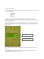
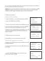
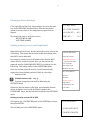
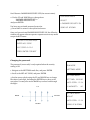
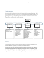
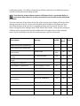
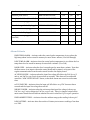
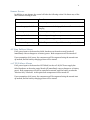
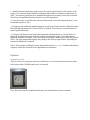
0
ULT FREEZERS Model: LABHP-17-ULTA, LABHP-17-ULTD,
LABHP-21-ULTA, LABHP-21-ULTD, LABHP-25-ULTD
OWNER’S INSTRUCTIONS
This manual describes how to operate and care for your appliance to get the best, most efficient,
performance.
READ THIS BOOK!
Note to Customer: This merchandise was carefully packed and thoroughly inspected before leaving our plant.
Responsibility for its safe delivery was assumed by the carrier upon acceptance of the shipment. As directed on
the side of your packing carton, claims for loss or damage sustained in transit must be made on the carrier as
follows:
A.) Visible Loss, Damage, Shortage External Evidence of Loss or Damage: This type of damage must be noted on
the freight bill and acknowledged by the carrier’s agent (driver) at time of delivery. Make sure you get a signed
copy. Send a written request for an inspection to the carrier.
B.) Concealed Damage: This type of damage may not be discovered until the unit is being unpacked. When
concealed damage is discovered, stop unpacking immediately and contact the carrier immediately to report
the claim and request an inspection. This should be done as soon as possible and, in any case, must be done
within 15 days or receiving the merchandise. If at all possible, do not move the item and save all packaging
material for carrier’s inspection.
C.) FAILURE TO FOLLOW THESE INSTRUCTIONS MAY RESULT IN THE CARRIER REFUSING TO HONOR YOUR
COMPANY’S CLAIM. UNDER NO CIRCUMSTANCES SHOULD THE MERCHANDISE BE RETURNED TO THE
MANUFACTURER. NO RETURNS WILL BE ACCEPTED WITHOUT PRIOR AUTHORIZATION.
Horizon Scientific
125 Varnfield Drive
Summerville, SC 29483
Phone: 800-648-4041
Fax:
843-821-8051
Warranty:
Two-Year Parts and Labor;
3 Years Compressor Parts
Revision Date
01/16/2015
1
Table of contents
Table of contents ............................................................................................................................. 0
Installation and start –up ............................................................................................................... 2
Control overview ............................................................................................................................. 3
Control operation ............................................................................................................................ 4
Setting the time and date. ........................................................................................................... 4
Changing the Temperature settings. ........................................................................................... 4
Changing Alarm Settings. ........................................................................................................... 5
Setting security access code (optional) ....................................................................................... 5
Control menus .................................................................................................................................7
Alarms ..............................................................................................................................................7
Alarm Criteria ............................................................................................................................. 9
Door Open ..................................................................................................................................10
Sensor Errors ............................................................................................................................. 11
AC Line Failure Alarm................................................................................................................ 11
12 V PS Failure Alarm ................................................................................................................ 11
Contacts and communications ...................................................................................................... 12
Remote alarm contacts............................................................................................................... 12
Maintenance intervals ................................................................................................................... 13
Maintenance procedures ............................................................................................................... 13
Air filter ...................................................................................................................................... 13
Condenser .................................................................................................................................. 13
Annual calibration...................................................................................................................... 13
Battery replacement ................................................................................................................... 13
Door gasket and vacuum relief port ........................................................................................... 14
Defrost ........................................................................................................................................ 14
Calibration.................................................................................................................................. 14
Options........................................................................................................................................... 15
Sample probe.............................................................................................................................. 15
Chart recorder. ........................................................................................................................... 15
Service and troubleshooting .......................................................................................................... 16
Chart recorder fuse..................................................................................................................... 16
Troubleshooting ......................................................................................................................... 16
Diagnostic mode ............................................................................................................................ 16
Specifications ................................................................................................................................. 21
Statement of Warranty ................................................................................................................. 22
2
Installation and start –up
NOTICE!
READ THIS MANUAL
It is necessary to read and understand this instruction
manual because failure to do so may result in (1)
substandard performance of your freezer, (2) damage to
your freezer and stored items, and also (3) possible
injury to operating personnel.
Placement clearance. The freezer must have a clearance of 5” in the rear and 6”
on each side so that sufficient air circulation is maintained for the removal of
exchange heat.
Start –up. Plug the ULT into power and engage the power switch/breaker located above the
power cord. The freezer will start, and the control panel will illuminate in the default status with
the words SYSTEM NORMAL in the message line, which is the top line of the control display.
The other lines will display available operating modes. You will note a pointer (˃) on the third
line.
The third line is always the active line, which means that you will enter that mode or menu by
pressing ENTER.
The default status:
Temperature Set Point (SP)
High temp alarm
Low temp alarm
Password security
Access code
-80ᵒC
SP+10ᵒC
SP-10ᵒC
OFF
1234
Power. The ULT requires a dedicated power outlet and circuit breaker: 20-amp circuit for 115V
mocels and 15-amp circuit for 230V models.
3
Control overview
The SYSTEM NORMAL display is a monitoring and access screen from which you may enter any
of the 4 control modes:
CONFIGURE
CALIBRATE
RUN
SETTINGS
The default setting will be sufficient for many hours while your freezer cools. You may
familiarize yourself with the control by setting the time, the date, and perhaps setting an access
code (numerical password).
Keys. The ENTER key serves to (1)accept menu selections and value changes and (2) advance
the active value through a row of values. The BACK key permits you to scroll back through the
values or menu.
UP and DOWN keys
BACK and ENTER keys
The UP and DOWN keys permit you to make numeric steps in settings and selections in the
menu
Warning lights are provided for Voltage boost (which means you should speak to your
maintenance department about low line voltage).
4
The Low battery warning light indicates that you need to replace the battery, the procedure for
which is explained in the chapter on Maintenance.
Alarms. Your freezer is protected with 21 alarm monitors. In the event of an alarm, an ALARM
MESSAGE will appear in the message line at the top of the screen and an alarm will sound.
Consult your owner’s manual. Consult the chapter on Alarms in this manual
Control operation
Setting the time and date.
SYSTEM NORMAL
1. Using the DOWN key, scroll to SETTINGS and press ENTER.
RUN MODE
2. Scroll to SET TIME and press ENTER
3. The active value in the date display (hours) will blink on and off.
Set the value using the UP and DOWN keys, and Press ENTER to
set the value (hour), and move to the next value (minutes).
Set minutes using UP and DOWN keys, press ENTER to save. The
active value will automatically scroll to the next settable value,
which is SET DATE.
˃SETTINGS MODE
SETTINGS MODE
˃SET TIME= 20:20:06
ACC CODE DISABLED
SETTINGS MODE
LO ALRM SET=
4. Follow the same process to set the date.
-80.0
˃SET DATE = 00/00/00
Pressing BACK at any time will cancel the entered values.
Changing the Temperature settings.
1.Navigate to the SETTINGS mode, and press ENTER to access the
SETTINGS mode menu.
2.Use the UP and DOWN keys to scroll to the TEMP SET line, then
press ENTER.
SETTINGS MODE
HI ALRM SET=
-60.0
˃TEMP SET =
-70.0
LOW ALRM SET=
-80.0
SETTINGS MODE
3. Use the UP and DOWN keys to set the temperature to the
desired value, then press ENTER
ADJUST
˃TEMP SET =
USING UP & DOWN
-70.0
5
Changing Alarm Settings.
1.The high (HI) and low (LO) alarm settings are set in the same
way as the TEMP SET described above. Note that the alarms
cannot be set any closer to the temperature set point than 10
degrees.
The alarms that may be set by the user are
HIGH TEMP ALARM
LOW TEMP ALARM
SETTINGS MODE
ACC CODE DISABLED
˃HI ALRM SET=
-60.0
TEMP SET=
-70.0
Setting security access code (optional)
When delivered, the freezer has the password security value in the
OFF setting. This means that access to modes and settings other
than RUN, can be addressed.
If you want to restrict access to all menus other than the RUN
menu, which is a read-only menu, then you may activate the
password security (PASSWRD SECURITY) by switching it to the
ON setting. This setting resides in the CONFIGURE menu.
Once you activate password security, you will automatically
acquire the factory default password, which is a four-digit
numerical code.
Default access code: 1 2 3 4
You may change the code itself by addressing the
SETTINGS menu.
Please note the two menus on the right, and remember that the
choice of whether or not a code is needed is made in the
CONFIGURE menu; but the code itself is edited in the SETTINGS
menu.
CONFIGURE MENU:
Ring-back delay
Password security
(status message)
LCD contrast
Run battery test
Battery back up
Sample
SETTINGS MENU:
Set time
Set date
Access code )
High alarm
Temperature set
Low alarm
Setting security access ON of OFF
1.Navigate to the CONFIGURE mode on the SYSTEM level menu,
then press ENTER.
This will take you to the CONFIGURE menu.
SYSTEM NORMAL
˃CONFIGURE MODE
CALIBRATION MODE
6
Scroll down to PASSWRD SECURITY OFF (the current status).
CONFIGURE MODE
2. Use the UP and DOWN keys to change from
PASSWRD SECURITY OFF to
PASSWRD SECURITY ON,
And press ENTER.
ADJUST
˃ PASSWRD SECURITY ON
You have now activated password protection
3. Press BACK to return to the system level menu.
USING UP & DOWN
Once you have activated PASSWRD SECURITY ON, the following
window will appear when an operator requests access to any menu
except the RUN menu:
SECURITY ACCESS REQD
ENTER ACC CODE
ACC CODE= 0 0 0 0
PRESS ENTER FOR NEXT
Changing the password.
SYSTEM NORMAL
The password (access code) is only required when the security
setting is ON.
RUN MODE
1. Navigate to the SETTINGS mode line, and press ENTER
˃SETTINGS MODE
2 Scroll to the SET ACC CODE, and press ENTER
SETTINGS MODE
3. Set the access code by using the UP and DOWN keys to change
the value of each digit, and using the ENTER key to move to the
next value. You may also use the BACK key to move back through
the digits.
SET TIME= 00:00:00
˃ACC CODE= 1 2 3 4
HI ALRM SET=
UP
-40
SETTINGS MODE
BACK
ENTER
ADJUST
˃ACC CODE= 1 2 3 4
DOWN
USING UP & DOWN
7
Control menus
Note that the RUN mode provides a “view only” menu in which you can verify settings. This is
the normal mode of operation for the freezer. To make changes in the settings themselves, you
must move to one of the other operation modes, CALIBRATE, CONFIGURE, or SETTINGS.
Operating modes and mode menus
System
Normal
CALIBRATE
CONFIGURE
See calibration
chapter for
calibration details.
Ring-back delay
Password security
(Access code)
LCD contrast
Run battery test
Battery back up
Sample
RUN
(View only)
Version details
(control)
Condenser temp.
Heat exchanger temp.
Ambient temp.
Control temp.
Line voltage
Cycle period
Battery life
SETTINGS
Set time
Set date
Access code
(status message)
High alarm
Temperature set
Low alarm
Alarms
A series of alarms monitor the various operating conditions of the freezer. These alarms are
presented differently depending on the severity of the alarm condition.
The table below lists these alarms and also shows the method of notification. The “Message”
column shows what message will be displayed in the message center. The “Audible” column
shows if the audible device is activated. The “Ring Back” column indicates if the audible alarm
is repeated after a specific time frame. The ring back delay is user selectable in the
8
Configuration mode. The “Relay” column shows whether each alarm is of sufficient priority to
warrant activating the remote alarm contacts.
Note that the remote alarm contacts will always have a 30 minute delay to
activate to allow time for on-site personnel to react to and resolve the alarm
condition.
Upon the occurrence of any alarm, the top line of the message center display will list the alarm
message as shown in the list. In the case of multiple alarm conditions, the display will show
each alarm message on the top line in a repeating sequence on three second intervals. The
alarms will appear on the message center ONLY when in RUN mode. If the operator changes to
a different mode, the alarm LED and the audible alarm will remain active, but the message
center top line will display whatever the normal message would be in that mode.
Audible
Ring
Description
Message
High control probe temperature
HIGH TEMP ALARM
yes
yes
yes
Low control probe temperature
LOW TEMP ALARM
yes
yes
yes
Door is open
DOOR OPEN
Yes if ˃ 1
min.
yes
yes
Power failure – loss of AC input
voltage
Power failure – loss of 12V power
supply
AC LINE FAILURE
yes
no
yes
12V PS FAILURE
yes
no
yes
Wrong power connected
WRONG POWER
yes
yes
yes
High Ambient Temperature
HIGH AMBIENT TEMP
no
n/a
no
Low battery voltage
LOW BATTERY
yes
yes
no
High stage system failure
H S SYSTEM FAILURE
yes
yes
yes
Low stage system failure
L S SYSTEM FAILURE
yes
yes
yes
Air flow alarm (determined from
temp probes)
AIR FLOW PROBLEM
yes
yes
no
Low voltage alarm
LOW LINE VOLTAGE
yes
yes
yes
High voltage alarm
HIGH LINE VOLTAGE
yes
yes
yes
Control Probe failure
CONT PROBE FAILURE
yes
yes
yes
Heat exchanger probe failure
HS HX PROBE FAILURE
yes
yes
no
Back
Relay
9
Condenser probe failure
COND PROBE FAILURE
yes
yes
no
Ambient probe failure
AMB PROBE FAILURE
yes
yes
no
Sample probe failure (if installed)
SAMP PROBE FAILURE
yes
yes
no
Control Probe Unplugged
CONT PROBE UNPLUGD
yes
yes
yes
Heat Exchanger Probe Unplugged
HTEX PROBE UNPLUGD
yes
yes
yes
Condenser Probe Unplugged
COND PROBE UNPLUGD
yes
yes
yes
Ambient Probe Unplugged
AMB PROBE UNPLUGD
yes
yes
yes
Sample Probe Unplugged (if
installed)
SAMP PROBE UNPLUGD
yes
yes
yes
Failed Battery Test
FAILED BATTERY TEST
yes
yes
no
Alarm Criteria
HIGH TEMP ALARM – Activates when the control probe temperature is at or above the
high temp alarm level as stored in memory for more than 1 minute. (Not Cold Enough)
LOW TEMP ALARM - Activates when the control probe temperature is at or below the low
temp alarm level as stored in memory for more than 1 minute. (Too Cold)
DOOR OPEN – Activates when the door is sensed open for more than 1 minute. Note that
the door sensor is an input to the main control board and its status is to be part of the
regular communication from the main control board to the display board.
AC LINE FAILURE – Activates when the input line voltage falls below 80 VAC for 115 V
unit or 160 VAC for 230 V unit for more than 10 seconds. This alarm will override and
cancel the “LOW LINE VOLTAGE” alarm, so that both alarms are not active at the same
time.
12V PS FAILURE – Activates when the input 12V falls below 10.5 VDC for more than 2
seconds and the input line voltage does not fail.
WRONG POWER – Activates when the unit senses that input line voltage is above 150
VAC for a 115 V unit or below 160 VAC for a 230 V unit. There is a jumper located on the
main control board that will indicate whether the unit is wired for 115V or 230V operation.
HIGH AMBIENT TEMP – Activates when the ambient temp probe reading is above 36 C.
LOW BATTERY – Activates when the results of a battery test returns a reading of less than
11.0 VDC.
10
H S SYSTEM FAILURE – Activates when the high stage heat exchanger probe is unable to
reach at least -33 C after running the high stage compressor for 30 minutes.
L S SYSTEM FAILURE – Activates when the high stage heat exchanger probe reaches a
reading of -50 C or below.
AIR FLOW PROBLEM – Activates when a calculation shows that the difference between
the ambient temperature and the condenser temperature probes is greater than 10 C.
LOW LINE VOLTAGE – Activates when the incoming AC power voltage is below 90 VAC
on a 115 V unit or 180 VAC on a 230 V unit for more than 1 minute.
HIGH LINE VOLTAGE – Activates when the incoming AC power voltage is above 135 VAC
on a 115 V unit or 265 VAC on a 230 V unit for more than 1 minute.
PROBE FAILURE (Control, Heat Exchanger, Condenser, Ambient, Sample) – Activates
when either of the following conditions is detected on this probe: A resistance value over
250 ohms, indicating an open sensor, or a reading below 20 ohms, indicating a shorted
sensor. The same criteria will apply to the remaining probe failure alarms.
PROBE UNPLUGGED (Control, Heat Exchanger, Condenser, Ambient, Sample) – Each
probe has a two-pin logic control as part of its connector, which will be used to detect that
the sensor is properly connected. This alarm shows that the system detected this probe is
not connected. This same description applies to all probes.
FAILED BATTERY TEST – Activates when the result of a battery test returns a reading of
bad battery.
INITIALIZING
If the display board is unable to initialize properly, the message center will not display any
valid information. This will serve as the indication of a display board initialization
problem. If the main board fails to initialize properly, it will not be able to communicate
with the display board and the display board will report a communication problem, as
described elsewhere.
Door Open
A door open message is displayed in the message center whenever the door is opened. If
the door remains open for more than 1 minute, an audible alarm will sound, subject to
normal silence and ring back functions. If the door remains open continuously for 30
minutes, the remote alarm contacts will activate.
11
Sensor Errors
In addition to any alarms, the control will take the following action if it detects any of the
unit’s sensors as being in error
Alarm
Result
Control Probe failure
Both compressors will turn on and remain on.
Heat exchanger probe failure
Compressor control during pull down will revert to timed
staging
Condenser probe failure
Alarm only, no change in compressor control
Ambient probe failure
Alarm only, no change in compressor control
Sample probe failure
Alarm only, no change in compressor control
Line/boost voltage sensing
Unit will operate normally, with boost voltage circuit Off
AC Line Failure Alarm
If AC power input to the freezer has failed, hardware on the main control board will
immediately cause a changeover to battery power. Both compressors will be turned off.
Upon resumption of AC power, the compressors will be sequenced using the normal start
up method, and the battery charging process will be started.
12 V PS Failure Alarm
If AC power input to the freezer has NOT failed, but the 12V AD/DC Power supply has
failed, hardware on the main control board will immediately cause a changeover to battery
power. Both compressors will still be controlled as normal, until the battery reaches the
“Monitor Only” threshold. At this point both compressors will be turned off.
Upon resumption of AC power, the compressors will be sequenced using the normal start
up method, and the battery charging process will be started.
12
Contacts and communications
ONLY Authorized, trained electricians should attempt any connection
behind the service panels!
Remote alarm contacts
The Remote Alarm provides a NO (normally open) output, a NC (normally closed) output, and a
Common. The Schematic below represents the alarm state and wire colors.
Note:
1) The Remote Alarm contacts will have a 30 minute delay once they are tripped.
2) Always double check the continuity of the NO and NC contacts.
3) This procedure is for the Alarm only. There is no analog output of the freezer
temperatures.
A 4-20mA signal is available.
RS-232 Communication is available at the main control box and is meant to be accessed by
trained service personnel only.
13
Maintenance intervals
Maintenance item
Recommended interval
Air cleaner and Condenser
3 months
Calibration
1 year
Battery
1 year
Door gasket and vacuum relief port
Monthly minimum
Defrost
As needed
Maintenance procedures
Air filter
In most laboratory conditions, the air filter should be inspected monthly and cleaned once every
three months. Press the top of the filter cover to release the catch. The door will swing forward
allowing easy access to the washable prefilter.
Condenser
Anytime that the air filter is removed for cleaning, the condenser fins and coils should be
inspected for dust that impedes the flow of air over the coils. Such dust should be removed with
a vacuum cleaner. The fins on the heat exchanger are very delicate and are easily bent , so be
sure to avoid placing any pressure or impact on the fins while cleaning.
Annual calibration
The control temperature probe should be calibrated once a year. This procedure is described in
the Maintenance Procedures chapter under Calibration.
Battery replacement
Warning! Only authorized, trained electricians should attempt any access behind
the service panels!
The battery is located in the lower left-hand (handle side) corner of the compressor
compartment. It may be accessed by either removing the front or left-side cover panel. The
14
battery is secured with two carriage bolts, but it is only necessary to loosen one bolt to remove
the battery.
Be sure to disconnect the leads from the control box before removing the battery.
Door gasket and vacuum relief port
Any time that dirt or frost accumulation prevents the door from closing properly, the gasket
should be cleaned with a soft cloth. As a general rule, a minimum of once a month is
recommended.
When the door gasket is operating as designed, the only means of pressure equalization for the
chamber is the vacuum relief port behind the control panel. The vacuum relief port is equipped
with a built-in heater to reduce frost accumulation, but some frost can accumulate behind the
port on the freezer door. It is important to make a visual check for such accumulation whenever
the door is opened and remove any accumulation found.
Defrost
1. Switch off the unit breaker switch and disconnect the freezer from power.
DISCONNECT battery to avoid deep discharge. To disable the battery, scroll to the
CONFIGURE MODE and press ENTER. Scroll to BATTERY BACK-UP ON, and press
ENTER
Use the UP and Down keys to change to OFF, then press ENTER. Upon restart, this
configuration will automatically revert to the ON setting
2. Empty the freezer of contents and transfer them to another freezer. Leave the inner
doors open.
3. Place moisture absorbing material such as paper or cotton towels in the bottom of the
freezer and on the floor in front of the freezer.
4. Allow frost to melt and loosen. The lose frost can be removed carefully in order to move
the process along more rapidly.
5. Once the freezer is free of frost, use a mild non-chloride cleaning agent, rinsing with
water.
6. Close doors and restore power.
7. Depending upon your temperature set point, storage temperature should be fully
restored in 8 to 12 hours.
Calibration
This procedure allows the temperature readout on the control panel to be adjusted to match
your temperature standard. The calibration allows for an adjustment to “offset” only. There is
no adjustment for “slope” or “span” available through the control panel.
15
1. Install reference temperature probe next to the control probe located on the interior of the
freezer. The reference probe should be calibrated and traceable to a known standard such as
NIST. The reference probe has to be installed through the access panel on the rear of the unit.
This is best accomplished when the freezer is at room temperature.
2. Turn the freezer on and allow the unit to pull down and cycle at the desired setpoint, or use
the default setpoint of -80 C.
3. Navigate to the calibration mode through the control panel, and access the calibration menu.
Scroll through the menu until “Control Probe” is reached. Press Enter to access the menu for
control probe calibration.
4. Using the Up/Down Arrows, adjust the temperature displayed next to “Control Probe” to
match the temperature readout from the reference temperature probe. The temperature is
displayed in tenths of a degree. Then Press Enter to accept the calibration for the control probe.
Note1: The large temperature display may change value when you press Enter, depending on
how much calibration is required.
Note2: The maximum calibration on the temperature probes is +/- 5 C. If further calibration is
required, contact the technical service department for assistance.
Options
Sample probe.
There is access to a probe port at the rear of the freezer. It is uncovered when the access plate,
held in place with 6 Phillips head screws, is removed.
Chart recorder.
The 7-day chart recorder is added at the factory. See manufacturer’s owner’s manual.
16
Service and troubleshooting
Chart recorder fuse
The system fuse is located to the left of the power switch.
115V power supply for
optional chart recorder
and its associated fuse
Power switch
Troubleshooting
For information in addition to that listed in this manual, please call the manufacturer and
request help. There is an additional technical troubleshooting guide available for qualified
serving personnel.
Diagnostic mode
ONLY Authorized, trained technicians should access the Diagnostic mode!
This mode provides the service technician access to detailed information for the purpose of
evaluating the operation of the freezer and troubleshooting problems. This mode is
accessible only by means of a special set of key presses. The information available in this
mode will be displayed on the message center as follows.
Control probe temperature
Ambient probe temperature
Heat exchanger probe temperature
Condenser probe temperature
Sample probe temperature (if installed)
Control probe temperature (default in line 3 position)
17
Sensed line voltage
Sensed compensated voltage
The menu has the ability to scroll in reverse chronological order through all
logged events. The display in this mode will consist only of the date/time stamp
and the event message, and will not include the sensor readings as described as
output through the RS232 port.
To enter DIAGNOSTICS MODE:
While in RUN mode, press the BACK and SILENCE keys simultaneously. The
display will change to:
ENTER DIAG MODE?
CALIBRATION MODE
>RUN MODE
SETTINGS MODE
After this display is showing, the operator then must press the BACK and DOWN
keys simultaneously. The display will then change to:
ENTER DIAG MODE?
PRESS ENTER TO
START - BACK TO
CANCEL OR ABORT
If the user then presses the ENTER key, the unit will change to DIAGNOSTIC
mode:
18
DIAGNOSTIC MODE
SAMPLE TEMP = -79.0
CONTROL TEMP = -80.0
LINE VOLTAGE = 120
Note that the active line designator “>” does not appear in diagnostic mode,
except for the “DUMP EVENT LOG”, “CLEAR EVENT LOG”, and “DISPLAY
EVENT LOG” lines, as described below.
Scrolling the up and down keys will cause the display to move through the
various diagnostic parameters listed above, similar to other modes. When the
user reaches the DUMP EVENT LOG line, the display will appear as follows:
DIAGNOSTIC MODE
COMP VOLTAGE = 122
>DUMP EVENT LOG
CLEAR EVENT LOG
If the user presses enter at this point, the display will change to:
DIAGNOSTIC MODE
PRESS ENTER TO
> SEND COMMAND
NOW
BACK TO CANCEL
19
Pressing Enter at this point will result in the entire contents of the Event Log being output to the
RS-232 port. The display will then revert to the previous display. Pressing Back will only cause
a return to the previous display.
In Diagnostics Mode, Scrolling to the Clear Events log will cause the display to appear as
follows:
DIAGNOSTIC MODE
DUMP EVENT LOG
> CLEAR EVENT LOG
DISPLAY EVENT LOG
Pressing Enter will cause the display to change to:
DIAGNOSTIC MODE
PRESS ENTER TO
> CLEAR EVENT LOG NOW
BACK TO CANCEL
Pressing Enter will cause the entire Event Log to be cleared. The display will then
revert to the previous display. Pressing Back will only cause a return to the
previous display.
In Diagnostics Mode, when the user reaches the DISPLAY EVENT LOG line, the
display will appear as follows:
DIAGNOSTIC MODE
CLEAR EVENT LOG
>DISPLAY EVENT LOG
PRESS ENTER TO GO
20
If the user presses enter at this point, the display will begin showing event logs in
reverse chronological order, formatted as shown below:
EVENT LOG
yyyymmddhhmmss
[event message line 1 ]
[event message line 2 ]
21
Specifications
Model Number
1768
2168
Temperature Range
Inventory capacity
2568
-50C to -86C
20 racks
25 racks
30 racks
320 / 240
400 / 300
480 / 360
78.25 x 34.38 x 34.75
78.25 x40.1 x34.75
78.25 x 45.75 x 34.75
(HWD) inches
49.88 x 23.38 x 22.8
49.88 x 29.1 x 22.8
49.88 x 34.75 x 22.8
Required area
12.85 ft₂
14.38 ft₂
15.94 ft₂
Box capacity (2”/3”)
Dimensions exterior
(HWD) inches
Dimensions interior
Inner doors
5 insulated
Security
Key lockable door. Passcode protectable control
Refrigeration
CFC free
½ HP x 1/2 HP cascade
Insulation
5.5” to 6” FIP urethane
Door gasket
3-point sealing
BTU rejection
2150
2370
2580
Shipping weight
595
625
675
Performance
2ᵒC
Average stability
Average uniformity
±4.5ᵒC
Average uniformity
±4.5ᵒC
300 Btu/h @ 25ᵒ
Reserve capacity
Warm-up time
Sound pressure level
Average energy
consumption
Electrical
Breaker requirement
Plug
Agency listing
-80 to -50 in 5 hours.
-80ᵒ to 0 in 12 hours.
55 to 65 db A scale @ 5 feet, depending on location and testing
15 kW Hour/day
16.5 kW Hour/day
18 kW Hour/day
115V 60Hz
230V 60Hz
20 amps dedicated
15 amps dedicated
NEMA 5-20
NEMA 6-15
UL 471
22
Statement of Warranty
HORIZON SCIENTIFIC, INC. PRODUCT WARRANTY
Horizon Scientific, Inc. warrants to the original purchaser every new Horizon Scientific, Inc. refrigerated unit, the
cabinet and all parts thereof, to be free from defects in material or workmanship, when such unit is installed, used,
and maintained in accordance with provided instructions, for a period of two (2) years. The warranty period starts
two weeks from the date of shipment from Horizon Scientific, Inc. This two week period allows ample shipping
time so that the warranty will go into effect at approximately the same time your equipment is delivered. Unless
subject to prior written agreement with Horizon Scientific, Inc., this warranty does not allow for any warranty start
deferment greater than two weeks from date of shipment due to a delayed installation and/or start-up. By purchasing
any product from Horizon Scientific, Inc., you and any entity for which you are purchasing acknowledge and agree
to each and every provision contained herein, and all other Notices and Terms provided to Purchaser by Horizon
Scientific, Inc., which are hereby incorporated.
Under this warranty, Horizon Scientific, Inc., through its authorized service organizations, will repair, or at its
option, replace any part found to contain a manufacturing defect in material or workmanship without charge to the
owner for parts, service labor or any shipping or cartage costs. Replacement or repaired parts will be warranted for
only the unexpired portion of the original warranty.
ADDITIONAL THREE YEAR COMPRESSOR WARRANTY
In addition to the two (2) year warranty stated above, Horizon Scientific, Inc. warrants its hermetically and semihermetically sealed compressors to be free from defects in both material and workmanship under normal use and
service for a period of three (3) additional years from the end of the initial two (2) year warranty period, but not to
exceed five (5) years after shipment from Horizon Scientific, Inc.
Compressors determined by Horizon Scientific, Inc. to have been defective within this extended time period will, at
Horizon Scientific, Inc.'s option, be either repaired or replaced with a compressor or compressor parts of similar
design and capacity.
The three (3) year extended compressor warranty applies only to hermetically and semi-hermetically sealed parts of
the compressor and does not apply to any other parts or components, including, but not limited to, cabinet, paint
finish, temperature control, refrigerant, metering device, driers, motor starting equipment, fan assembly or any other
electrical components.
Horizon Scientific, Inc.’s sole obligation under this warranty is limited to either repair or replacement of parts,
subject to the additional limitations below. This warranty neither assumes nor authorizes any person to assume
obligations other than expressly covered by this warranty.
NO CONSEQUENTIAL DAMAGES. Horizon Scientific, Inc. is not responsible for economic loss; profit loss; or
special, indirect or consequential damages, including without limitation, losses or damages arising from contents
spoilage claims whether or not on account of refrigeration failure, electrical failure, power failure, or compressor
failure. HORIZON SCIENTIFIC, INC.’S MAXIMUM CUMULATIVE LIABILITY RELATIVE TO ALL
CLAIMS AND LIABILITIES, INCLUDING OBLIGATIONS UNDER ANY INDEMNITY, WHETHER OR NOT
23
INSURED, SHALL NOT EXCEED THE COST OF THE PRODUCT(S) GIVING RISE TO THE CLAIM OR
LIABILITY.
WARRANTY IS NOT TRANSFERABLE. This warranty is not assignable and applies only in favor of the
original purchaser/user to whom delivered. Any such assignment or transfer shall void the warranties herein made
and shall void all warranties, express or implied, including any warranty of merchantability or fitness for a particular
purpose.
NO IMPLIED WARRANTY OF MERCHANTABILITY OR FITNESS FOR A PARTICULAR PURPOSE.
There are no other warranties, express, implied, or statutory, except the two (2) year warranty and the additional
three (3) year compressor warranty as described above. These warranties are exclusive and in lieu of all other
warranties, including implied warranty and merchantability or fitness for a particular purpose. There are no
warranties which extend beyond the description on the face hereof, whether based on contract, warranty, tort
(including negligence), strict liability, indemnity, or any other legal theory, and whether arising out of warranties,
representations, instructions, installations, or non-conformities from any cause. Purchaser further acknowledges that
the purchase price of the Product reflects these warranty terms and remedies.
ALTERATION, NEGLECT, ABUSE, MISUSE, ACCIDENT, DAMAGE DURING TRANSIT OR
INSTALLATION, FIRE, FLOOD OR OTHER EXTERNAL CAUSES.
Horizon Scientific, Inc. is not responsible for the repair or replacement of any parts that Horizon Scientific, Inc.
determines have been subjected after the date of manufacture to alteration, neglect, abuse, misuse, accident, damage
during transit or installation, fire, flood or other external causes. It does not apply to defects resulting from failure to
properly install, operate or maintain the product in accordance with the printed instructions provided, or damage
caused by the storage of any corrosive material that comes in contact with the interior or exterior portions of the
cabinet, or the use of spark producing equipment or containers (such as galvanized or carbonized steel containers)
that come in contact with any interior portion of the cabinet.
OUTSIDE U.S./CANADA. This warranty does not apply to, and Horizon Scientific, Inc. is not responsible for, any
warranty claims made on products sold or used outside the United States and Canada.
CHOICE OF LAW/VENUE. The laws of the State of South Carolina shall govern the validity, interpretation and
enforcement of this warranty, regardless of conflicts of law principles. Purchaser agrees that proper venue for any
action to enforce the terms of this warranty shall be the Dorchester County District Courts, South Carolina.
Purchaser submits the jurisdiction of such courts over the Purchaser and the subject matter of any such action. Any
action for breach of these warranty provisions must be commenced within one (1) year after that cause of action has
accrued.
WARRANTY CLAIMS. To obtain prompt warranty service, simply contact the manufacturer at 800-648-4041.
Horizon Scientific, Inc.’s shipping records showing date of shipment shall be conclusive in establishing the warranty
period. All claims should include: model number of the refrigerator, the serial number of the cabinet, proof of
purchase, date of installation, and all pertinent information supporting the existence of the alleged defect. Any
repairs must be authorized by Horizon in order for the warranty to be honored.
LabRepCo, LLC
101 Witmer Rd., #700
Horsham, PA 19044
Phone: 800-521-0754
Fax: 215-442-9202