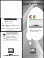
1
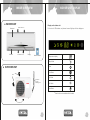
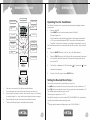
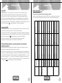
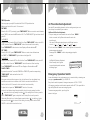
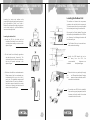
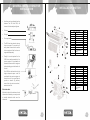
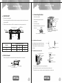
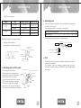
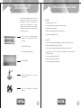
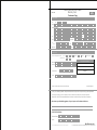
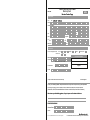
Warranty Registration System
3 STAR
2 STAR
Help us to serve you better by registering
your product for Warranty
Web
Register at www.onida.com
Telephone
Call Centre No. 0XX-39889000(0XX-STD Code of
State Capital)
Post / Visit
Post the Warranty Registration Card & Service Centre
Copy or Visit the Nearest Service Centre.
Model:
S09FLT-L3/ S12FLT-L3/ S18FLT-L3/ S24FLT-L3
S09FLT-L4/ S12FLT-L4/ S18FLT-L4
As per Government of India’s E-Waste (Management and Handling)
Rules, 2011(effective from May 1st, 2012) the product purchased by you
is to be considered as E-Waste and cannot be disposed off with your
general household waste. It should be disposed of through the company’s
collection center so as to prevent any damage to environment
Collection Center address
Mirc Electronics Ltd.Village Kudus,Bhiwandi Wada road,
Taluka Wada., Dist. Thane - 421312,Tel no. 952525 220375/377
Visit at : www.onida.com for details about collection Centers.
We request you to make a note of the above details and support us
in our endeavour to ensure an environmental friendly nation.
AIR CONDITIONERS
The unit displayed is for representational purposes only. Actual unit may vary.
Dear customer
Congratulation on buying ONIDA Air Conditioner.
Your Air Conditioner comes with ONIDA Guarantee of Quality
as detailed in the manual.
ONIDA takes great pride in providing its customers with stateof-the-art products that adheres to international quality
standards.
ONIDA is committed to following quality policy laid by our
chairman and managing director Mr. G. L. Mirchandani.
“We are committed to quality and strive for continuous
improvement through innovation and human development to
give customer better value for money always”
ONIDA stands committed to provide the ultimate customer
satisfaction, as nothing brings us greater joy than having
satisfied customers of ONIDA.
At ONIDA, feedback and suggestions based on your product
usage experience is greatly appreciated.
Please contact to us at [email protected]
G. Sundar
Chief Executive Officer
IMPORTANT :
Please read this owner’s manual carefully and thoroughly
before installing and operating your room air conditioners.
Please retain this owner’s manual for future reference after
reading it thoroughly.
CONTENTS
Salient Features
1
Inside Overview
2
Indoor Unit Display
3
Remote Overview
4
Operations
5
General Instructions for Installation
12
Installation Sketch
15
Installation of Model
16
Take care of your Air Conditioner
20
Precautions to be taken
21
Trouble Shooting Chart
23
Installation and Satisfaction Report
25
Warranty Terms & Conditions
27
Preventive Maintenance Service Coupon
29
Warranty Card(Customer Copy)
31
Warranty Card(service Centre Copy)
33
SALIENT FEATURES
0.8T/ 1.0T / 1.5T Split Air Conditioner
Model Code :
S09FLT-L3/ S12FLT-L3/ S18FLT-L3/ S24FLT-L3
S09FLT-L4/ S12FLT-L4/ S18FLT-L4
3 STAR
• Aesthetics:a) Unique Flat Panel
b) Sleek Indoor Unit
• Performance:a) 3 Star / 2 Star Energy Saver BEE Rated
b) High BTU Tropicalised Compressor
c) Trapezoidal Inner Grooved Tube
d) Large L - Shaped Condenser Coil
• Features:a) i-Cool Function- For Instant Cooling
b) Smart Sleep with 4 personal preference modes
c) Turbo- Cool Function for Cooling in adverse Condition
d) 3 Stage Filtration- For Better Air Quality
e) Auto-Restart
• Safety & Reliability:a) Low Deration Factor
b) Hydrophilic Fins
c) Full Function LCD Remote
d) Special Insulation on the Air Vent
e) 5-Stage Epoxy Polyester Painting
f) Rugged Construction With Thicker Gauge Steel
1
INSIDE OVERVIEW
n
INDOOR UNIT DISPLAY
INDOOR UNIT
Front panel
Deflector
Display on the indoor unit.
For the icon of LED windows, only relevant icons will light up with their displays on.
Return warm Air in
Conditioned Air out
Display
Remote controller
Temperature display
Sleep Mode
n
Timer
OUTDOOR UNIT
Cool Mode
Air in
Dry Mode
Connection
pipe and
connecting wire
Fan Mode
Heat Mode
*Heat mode is not available with all models.
Exhaust Air
2
3
OPERATIONS
REMOTE OVERVIEW
Signal ejecting window
OPERATION DISPLAY
Operating Your Air Conditioner:
MONEY SAVED
ENERGY SAVER
MODE
Your Split Air Conditioner can be conveniently operated using the intelligent cordless
remote control.
DISPLAY ON/OFF
BUTTON
CLEAN
1.
SWING FAN AUTO
TURBO MODE
RUN/STOP
TURBO
ENEGRY MONEY
MONEY DISPL
DISPLA
AY
SAVER SAVED ON/OFF
Your AC switches on with parameters that were set before power was switched
off. The unit receives the signal with "BEEP" tone and your AC starts operation.
OPERATION MODE
TEMPERATURE
ADJUSTMENT
TEMPERATURE
ADJUSTMENT
MODE
Time Delay: To protect the compressor, a time delay is incorporated in the circuit.
The Time Delay ensures that the compressor switches ON only after a delay of about 3
minutes.
TIMER ON/OFF
FAN SPEED
FAN SPEED
MANUAL/AUTO
SWING
SWING
TIMER ON/OFF
SLEEP
SLEEP
SLEE
P
i-Cool CONTROL
i-cool
C.F.
C.F
ON/OFF
Switch on the MCB.
Press ON/OFF button on remote handset to switch ON the AC.
All icons will glow once.
C.F
C.
F.
+
2.
Press the “MODE” Button for Auto, Cool, Dry, or Fan Mode selection.
3.
Press the "FAN” Button to set the Fan Speed. Each press changes the fan speed
from Low-Med.- High-Auto Fan speed. The selected fan setting symbol can be
C.F.
C.F
-
MANUAL
seen on the LCD.
i-cool CONTRO
CONTROLL
4.
The Set Temp. is displayed on LCD, Press button ”
“ to increase and “
“ to the
decrease the temperature.
BACK VIEW
5.
To switch off the AC, press the same ON/OFF Button.
Setting the Desired Room Temp.:
You can set the temp. at which you would like your room to be.
Press " " button to increase the set temp. On every press, the temp. increases by 1 OC.
1.
Open back cover and put 2 Nos. AAA size alkaline batteries.
Press "
2.
The remote signal can be reached upto six metres from the indoor unit.
The two digit display shows the set temp. on LCD.
3.
When the button is pressed on remote, indoor unit will “beep” once, indicating
the receipt of signal. If no “beep” sound is heard, press the button once again.
The setting temp. range is from 16- 31OC.
4.
Remove batteries if remote control has not been used for long time.
5.
*Heat mode & Money Saved
" button to decrease the set temp. On every press, the temp. decreases by 1OC
Your split AC operates in one of four modes, AUTO-COOL-DRY-FAN. The modes button
cyclically chooses between these operating modes.
is not available with all models.
*Cooling capacity measured at High speed, as per IS 1391:1992 Part 2
4
5
OPERATIONS
OPERATIONS
i-Cool (With Ceiling Fan Controller):-
The AUTO Mode :
1. Press "MODE" button to cyclically step through the AUTO-COOL-DRY-FAN modes and stop
when AUTO mode is selected.
2.
Auto symbol can be seen on the Remote panel.
3.
In this mode, the fan speed is changeable.
4. In the AUTO mode, unit will run in preset temperature and temperature can’t be changed.
The COOL mode:
In the cool mode, the compressor is in operation and your AC functions in the standard
operating mode, cooling your room to the desired set temp.
1.
2.
Press "MODE" button to cyclically step through the AUTO-COOL-DRY-FAN modes and stop
when cool mode is selected.
symbol can be seen on the Remote panel when you select the cool mode.
In this mode, you can change the temp. settings by pressing " " and “
” temp. buttons.
You can change the fan speed setting by pressing FAN button.
If the Room temp. is more than the set temp., then the compressor & outdoor FAN will
remain ON and perform the Cooling operation. If the room temp. achieves the temp. less
than set temp., then the compressor & outdoor FAN will remain OFF.
The DRY Mode:
One touch auto cooling control of AC & Ceiling Fan*.
This mode is activated by pressing i-cool key on remote. To enable mode to control Ceiling
Fan also, main switch of Ceiling Fan has to be in ON position.
In this mode initially the AC & Ceiling Fan start in special mode at super high speed
designed to give instant cooling and comfort. Compressor will start immediately in this
mode. After some time the AC and Ceiling Fan work at special mode which gives powerful
cooling along with energy savings. During this mode the speed of AC Fan and ceiling fan
changes automatically with time and temperature change. Set temperature also changes
automatically. During this operation both AC and Ceiling Fan are coordinated to ensure
speed cooling with energy savings. While AC is in this mode temp, Fan Speed, Timer, Sleep
keys are inactive and these parameters cannot be changed.
To quit i-cool mode Press MODE or TURBO or Energy Saver Button.
3.
In the DRY mode, your AC reduces the humidity within the room faster.
When the room temp. is more than 16OC then only the DRY mode operates.
1.
2.
Press "MODE" button to cyclically step through the AUTO-COOL-DRY-FAN modes and stop
when DRY mode is selected.
symbol can be seen on the Remote panel when you select the DRY mode.
3.
In DRY mode, Indoor FAN will run at low speed, Compressor & Outdoor Fan will remain
ON & run in preset temperature. Temperature cannot be changed.
The FAN Mode:
1. Press "MODE" button to cyclically step through the COOL, FAN, DRY & AUTO modes and
stop when FAN mode is selected.
2.
symbol can be seen on the Remote panel when you select the FAN mode.
3.
In FAN mode, only Indoor FAN will run at set speed and Compressor & Outdoor Fan will
remain off.
4.
In this mode, you can change the Indoor FAN Speed, but you can not set the desired TEMP.
6
i-Cool (Without Ceiling Fan Controller):In case i-cool ceiling fan controller which is an optional accessory has not been installed, the
AC will work in special i-cool mode on pressing i-cool key on remote. In this mode initially the
AC work start at super high speed designed to give instant cooling and comfort.
Compressor will start immediately in this mode. (Fan noise will be higher during this period
due to higher air throw).After some time the AC will work at special mode which gives
powerful cooling along with energy savings. During this mode the speed of AC Fan speed
changes automatically with time and temperature change. Set temperature also changes
automatically. While AC is in this mode temp, Fan Speed, Timer, Sleep keys are inactive and
these parameters cannot be changed. To quit i-cool mode Press MODE or TURBO or Energy
Saver Button.
* i-cool Ceiling Fan Controller is an optional accessory and is not part of the AC . Cost of icool ceiling fan controller and its installation is extra and not included in the AC.
7
OPERATIONS
OPERATIONS
Turbo MODE:
SMART-SLEEP MODE:
Pressing Turbo key on remote activates the Turbo function and air conditioner goes to
powerful cooling. During this Mode temperature and fan speed cannot be changed.
3 Stage Smart-Sleep with 4 personal preference modes,
8
Cools at Set Temp all along
Cools at Set Temp all along
Cools at Set Temp + 2ºC after 2 Cools at Set Temp + 2ºC after 2
hours
hours
Bio Sleep -Personal
Preference mode 3
Set Temperature - Cools at Set Temp + 1ºC / hour for
next 2 hours.
24ºC - 27ºC
Set Temperature - Cools at Set Temp all along
28ºC - 31ºC
Cools at Set Temp all along
Cools at Set Temp all along
Cools at Set Temp + 3ºC after Cools at Set Temp + 3ºC after
3 Hours
3 Hours
Cools at Set Temp + 1ºC after 7
hrs
Cools at Set Temp + 2ºC for
next 5 hours
Set Temperature - Cools at Set Temp + 1ºC / hour for
next 2 hours.
24ºC - 27ºC
Set Temperature - Cools at Set Temp all along
28ºC - 31ºC
Set Temperature - Cools at Set Temp + 1ºC / hour for
next 3 hours.
23ºC - 16ºC
Cools at Set Temp all along
Cools at Set Temp all along
Cools at Set Temp + 2ºC after 7
hrs
Cools at Set Temp after 8 hrs
Cools at Set Temp + 2ºC for
next 6 hours
Cools at Set Temp + 3ºC for
next 4 hours
Cools at Set Temp + 1ºC after 8
hrs
Cools at Set Temp + 3ºC for
next 5 hours
Set Temperature - Cools at Set Temp + 1ºC / hour for
next 3 hours.
23ºC - 16ºC
Set Temperature - Cools at Set Temp + 1ºC / hour for
next 2 hours.
24ºC - 27ºC
Set Temperature - Cools at Set Temp all along
28ºC - 31ºC
Set Temperature - Cools at Set Temp + 1ºC / hour for
next 3 hours.
23ºC - 16ºC
Stage 3
Cools at Set Temp + 2ºC after 2 Cools at Set Temp + 2ºC after 2
hours
hours
Bio Sleep -Personal
Preference mode 2
Smart Sleep Personal
Preference modes
When AC is in any mode other then i-cool mode, Ceiling fan speed can be controlled using
remote control. To enable this Ceiling fan mains have to be in ON position. Press C.F. ON key
on remote to start ceiling fan. Ceiling fan speeds can be changed by pressing C.F. + key on
remote to increase and C.F . – key on remote to decrease. The speeds can be varied by 5
steps by pressing C.F. + and C.F. – keys on remote. Press C.F. OFF key on remote to switch
off ceiling fan. (
symbol will appear on remote control display).
Temperature Set
Condition
Ceiling fan speed can be controlled only through AC remote control as all other manual
controllers are bypassed while installing i-cool fan controller.
Cools at Set Temp + 1ºC / hour for
Set Temperature next 2 hours.
31ºC - 16ºC
Ceiling Fan Manual Operation – only when optional i-cool ceiling fan
controller is installed:
Smart Sleep -Personal
Preference mode
Normal
Bio Sleep -Personal
Preference mode 1
.
Stage 2
Press again to cancel this operation. The unit will run in COOL Mode
Stage 1
In this mode temperature cannot be changed & Fan speed can be changed.
Wake Up stage
In this mode the AC works on a preset temperature of 25 degree centigrade at selectable fan
speed. Compressor will work in cyclical ON/OFF mode to keep the room temperature within 2
degree of set temperature. (
symbol will appear on remote control display).
Deep Sleep Stage
Energy Saver MODE:
Pressing Energy Saver key on remote activates Energy Saver function to keep room normal
temperature by reducing compressor run hours to get more savings.
To switch on Smart-Sleep operation, press “SLEEP” button on remote and the indoor fan
will run at low speed. Press the same button four times to quit the Smart-Sleep mode.
Initial Sleep Stage
In this mode the AC works on a preset temperature of 18 degree centigrade at high fan
speed. Compressor will start immediately in this mode and will continue to operate till set
temperature is achieved .Thereafter it will work in cyclical ON/OFF mode to keep the room
temperature within 2 degree of set temperature. Press again to cancel this operation. The unit
will run in COOL Mode. (
symbol will appear on remote control display).
123
9
OPERATIONS
OPERATIONS
TIMER Operation:
You can program your split AC to switch itself ON or OFF at particular time.
Air Flow direction Adjustment:
Maximum set time is 24 hrs, with 1.0 hr increment .
ON TIMER:
Your split AC has oscillating louvers for uniform cooling around your room.
When the AC is "OFF" (in standby), press "TIMER-ON/OFF" Button on remote to use this feature
as the TIMER. (make sure that MCB switch is "ON". The "TIMER-ON/OFF" light on Indoor unit will
glow ON.
For EXAMPLE:
Suppose you want to switch ON the AC after 8 hrs. Press "TIMER-ON/OFF" button, when AC is
in OFF condition. Press the “TIMER ON/OFF” button 8 times to set 8 hrs time delay.
Press "TIMER-ON/OFF" button to set on timer. Display on Remote will show "8”.
OFF TIMER:
You can stop the oscillation if you so desire.
Up/Down Air Direction Adjustment:
1. 5 step air swing can be achieved for the one time Press “ SWING ”
button on remote, the Up/Down air louvers will move to the
specific angle.
You can set 5 different angle settings, to set Up/Down louvers in
order of (1)
(2)
(3)
(4)
(5)
2. For the next Press “ SWING “ button to start Up/Down Air Louver which
starts swinging automatically.
Press again the “ SWING “ button to stop swinging at specific
position.
When the AC is "ON", press "TIMER-ON/OFF" Button on remote to use this feature as
the TIMER. The "TIMER-ON/OFF" light on Indoor unit will glow ON.
For EXAMPLE:
Suppose you want to switch OFF the AC after 8 hrs. Press "TIMER-ON/OFF" button, when AC
is in ON condition. Press the “TIMER ON/OFF” button 8 times to set 8 hrs time delay.
Press "TIMER-ON/OFF" button to set OFF timer. Display on Remote will show "8”.
CANCEL TIMER:
If you want to cancel the Timer either TIMER ON or TIMER OFF, press the corresponding
“TIMER-ON/OFF“ button and set the time to 0:0.
CLOCK SET:
Left/Right Air Direction Adjustment:
Move manually, the left right air
louver at desired position as shown
in following figure.
Emergency Operation Switch:
In case the batteries in the remote are worn out, or remote is faulty or misseing, use
emergency operation switch (*) to ON/OFF AC.
As long as remote controller is power on, the clock will run and it can be adjusted in any
condition even when the air conditioner is off. While the remote is electrified for the
Every time the switch is pressed, it changes in sequence of COOL Ý STOP.
first time, the time is 0:00, means the clock counts the time automatically.
To adjust the clock press the “TIMER ON/OFF” button for 10 seconds,
In Emergency operation mode the set temperature will be 24OC, Fan speed will be
high and Up/Down Air louvers are in swinging mode.
the time of hour flashes, during this period add the time of hours by pressing the button
To access emergency switch, open the grill as
“ “ and reduce the time by pressing the button” “ .After setting the time of hour, press the
button “TIMER ON/OFF” again to adjust the time of minute(Do not need to press for
10seconds.)When the time of minutes flashes, press the button “ “ to add time of minute,
and press the button“
“ to reduce it. Finish setting of minute, press the button TIMER
ON/OFF for the third time to confirm the clock.
shown in the figure.
10
11
GENERAL INSTRUCTIONS FOR
INSTALLATION
GENERAL INSTRUCTIONS FOR
INSTALLATION
Locating the Outdoor Unit
Locating the indoor and outdoor units
properly will help optimise the performance of
your airconditioner. While your Onida /
Dealer's Technician will be happy to guide you
on the best location for your airconditioner,
here are a few helpful hints.
The outdoor unit houses the compressor,
condenser fan and electrical components.
The heat removed from the room is expelled
to the atmosphere through the outdoor unit.
Locating the Indoor Unit
Once again, the Onida / dealer's Technician
will ensure optimal installation of the ODU for
you. However, the following information will
be of interest to you.
• Locate the IDU for the best cool air
circulation. Preferably, there should be
no obstructions nearby, as shown in the
adjacent figure.
• The Outdoor Unit can be mounted on a
wall, sunshade or skirting.
• Do not locate the unit directly opposite a
door which is opened frequently. The
cold air will go out of the room each time
the door is opened, as shown in the
adjacent figure.
• Ideally, the ODU should not be too
far a w a y f r o m t h e I D U ; t h e
recommended
distances are
marked in
the adjacent figure.
• Ensure that air can pass freely through
the
unit. Please allow at least 2 meters
free
space on the air outlet side, and 0.3
meters on the air inlet side.
• All indoor units will form condensate water.
Please ensure that the condensate can
be drained out of the room to a toilet /
pantry, etc. The installation engineer will
make sure that a "U" bend is provided in
the drain to prevent insects from coming
into the room through the drain tube, as
shown in the adjacent figure.
• If more than one ODU is to be installed,
they must be properly separated, so that
the warm air from the outlet of one does
not enter the inlet of the other.
12
13
GENERAL INSTRUCTIONS FOR
INSTALLATION
INSTALLATION SKETCH
• Avoid long and complicated routing
between the IDU and ODU, as
shown in the three adjacent figures.
15cm above
• Too long
1
2
Indoor unit accessories
15c
m le
ft
• Too high
G
• Too many bends
7
15cm
• The ODU must be placed on strong
frame or support. If mounted on a
wall, please ensure that the wall is
thick enough and that the frame is
supported adequately.
C
ove
• Finally, it is most important for the
ODU to be easily accessible to the
service engineer. It is advisable to
discuss the same with the engineer
before deciding upon the location of
the unit.
B
Mounting Plate
1
2
Tapping Screw ST4 X 25
5
3
Expansion Rubber Plug
5
4
Expansion Bolt
2
5
Battery
2
6
Remote controller
1
7
Felt
1
8
Adiabatic Underlay
1
9
Connecting Cable
10
Drain Joint(supplied by
customer)
remark
11
Clamping cover of pipe
1
1
D
11
Installation accessories
6
If the ODU is to be located on a high
ledge, adequate space must be
provided for the service engineer to
service the unit. It is a good idea to
provide a catwalk (a platform)
around the unit and access door /
window to the Unit.
After the location of the outdoor unit and
indoor unit is finalised, you must provide
a suitable electrical outlet near the
indoor unit.
F
H
250cm ab
Electrical outlet
right
Quantity
1
60cm above
5
Quantity
A
Connecting Cable
1
B
Bonding tape
1
C
Clamp
3
D
Cement nail
5
E
Drain hose
1
F
Opening cap
1
G
W all -hole cover
1
H
Indoor wall-hole cover
1
I
Putty
J
Air proof oil
Shockproof rubber
cushion(supplied by
customer)
e
v
abo
m
30c
30c
mab
To
O
DU
DU
O
To
ove
Air Outlet
MCB
K
E
1
e
bov
cma
200
9
1
remark
A
60c
ma
bov
e
STABILISER
A
A
14
15
INSTALLATION
INSTALLATION
n
n
INDOOR UNIT
Connecting of cables
1. Open the front panel
1. Fitment of mounting plate
Electrical box cover
2. Dismentle the electric box cover
The mounting plate should be fitted on the structural part of wall on which indoor unit
is to be installed.
Indoor unit
terminal
and fastener
Screw
3. Connect the cable
2. Drill two holes at a distance of 450 mm between them for the expansion bolts.
4. Reassemble the fastener and electric
fasten string at the central hole
at least
B from top
C or more
A or more
Diagram
box cover.
Fastener
Screw
from sidewall
from sidewall
Connecting cable
Indoor unit terminal
mounting
plate
Pull the Connecting cable’s
wire in completely
Connecting cable
plumb
n Installation of indoor unit
Model
1.0 T
1.5 T
A
175
175
After putting the pipe assembly through
the wall, attach the indoor unit to the
mounting plate on the wall as shown in
the figure.
Dimensions in mm
C
B
260
245
260
245
Mounting Plate
Indoor unit
Rib of indoor unit
Bottom
n Installation of outdoor unit
Connect diagram
Outdoor unit terminal
n
Drill on the wall
Indoor unit terminal
Connecting
cable
Confirm the position of holes and drill holes of diameter 65 mm on the wall
Connecting
cable
White
Blue
180mm
Yellow/Green
Outdoor unit terminal
18
10
Insert Ruler
• The connecting cables must be clipped together.
Center of Hole(Ø65mm)
Align Ruler with straight line
• Special cable to be used to connect indoor unit and outdoor unit.
• The electric box cover must be mounted on its position on outdoor unit.
16
17
INSTALLATION
INSTALLATION
n Connecting of pipes
Model
1.0 T
1.5 T
Pipe
Diameter of pipe
Torque (N • m)
Liquid pipe
6.35 mm
13.7--17.6
Gas pipe
Liquid pipe
Gas pipe
12.7 mm
6.35 mm
49.0--56.4
13.7--17.6
12.7 mm
49.0--56.4
n
Add refrigerant
• If the connecting pipe is longer than 7 meters, add refrigerant as needed. Add
amount A= (Lm-7m) 15g/m.
(A: add refrigerant amount, L: the length of connecting pipe)
the length of connecting pipe (m)
7
8
9
10
add amount (g)
0
15
30
45
• Add refrigerant with the spring balance, as specified above.
n Sealing the wall hole and clamping the pipe
connecting pipe
• Use putty to seal the wall hole.
Indoor unit
• Use pipe fastener to clamp the pipe on wall
Fixing Hook
Liquid side piping
Bottle of storage refrigerant
air proof with putty
Finally wrap it
with tape
n
Gas charging hole
Bottle’s valve of storage refrigerant
Mounting Board
Gas side
piping insulation
Mounting Board
Closing valve
Outdoor unit
Gas pipe
External connection
electric wire
Gas side piping
Liquid pipe
Liquid side
piping insulation
n
Water
drainage
pipe
• Proceed leak test (with leak detector or soap water.) and inspect connecting
cables before test operation.
Test procedure: (Control by emergency operation switch or remote
controller) For detailed operation, see OPERATION OF AIR CONDITIONER
in the manual.
Discharge the air of the units:
Liquid closing valve
It can be used as vaccum pump.
Remove screw cap of closing valve and
Gas closing
gas charging hole; Open the closing valve valve
with Allen wrench(turn 90 clockwise),
then push the gas hole for about 10 seconds,
(When a gas like fog appears, it indicates
that the air of unit has been discharged)
put back the screw cap of gas charging hole.
Do the leak test with leak detector or soap water.
Test
Liquid connecting pipe Cap
Allen Wrench
Gas connecting
pipe
Screw Cap
Screw Cap
Gas
Charging
Hole
18
19
TAKE CARE OF YOUR
AIR CONDITIONER
PRECAUTIONS TO BE TAKEN
Most of the maintenance work on your air
c o n d i t i o n e r, d u r i n g w a r r a n t y a n d
subsequently under the maintenance
contract, will be handled by a trained
technician. However, there are some simple
maintenance jobs that you, as a user, should
carry out on your own.
Do's (
)
• Seal all air gaps in the room
• Choose the right temperature to avoid over cooling
• Ventilate the room regularly.
• Switch off the power supply if not in use for long.
• Unplug the unit while cleaning.
• Lift the cover by applying gentle
pressure on both sides and lift it
upwards
Don't's (
X)
• Don't leave the doors and windows open when the air conditioner is on.
• Don't use hot water to clean your front grill
• The filters will be visible
• Don't use scouring powder, harsh soaps, wax or polish on the grill.
• Don't switch on the air conditioner immediately after switching it off.
Wait for 2 minutes.
• Lift the filters slightly upwards
• Don't operate with a clogged filter
• Don't block air intake & outlet vents
• Pull out the filters
• Don't change setting unnecessarily.
• Wash the filters under a tap until
they are clean
• Do not use detergents for cleaning
the filter.
20
21
TROUBLE SHOOTING CHART
Symptoms
Unit does not start
Possible Causes
MCB has tripped
Reset MCB
Fuse has burnt
Replace fuse wire
Input voltage to the
stabiliser is below
acceptable range
If the input voltage to
the stabiliser is below
the acceptable range,
the AC will not operate
The On/Off key is not
pressed
Units does not cool
(Even after the normal
Time Delay of approx.
2/3 minutes for
compressor to start)
Suggested Remedy
Press the On/Off key
on the control panel or
the remote
The airflow paths are
not free
Remove all
obstructions to make
the airflow paths free
The Units is in the fan
mode
Change to COOL
mode
Selected temperature is
more than room
temperature
Make the selected
temperature less than
room temerature
Air-filter is not clea
Clean the air-filter
Note: If the unit still does not work, or if any other types of symptoms are encountered,
shut off the mains (switch fuse unit) and call the service engineer.
22
23
INSTALLATION & SATISFACTION
REPORT
Customer Name :
Address
Phone[O]
[R]
Unit Model
Unit Serial Number
Dealer Name
Invoice Number
Date of Purchase
Date of Installation
MCB Rating
Current (Amps.)
Cable Size
Ambient Temp. ( OC)
Earthing
Room Temp. (OC)
Stabiliser
Grill Temp. (OC)
Input Voltage
Remote Operation
Customer's Response : To be filled up by the Customer
1. Installation completed within:
12hrs( ), 24 hrs( ) , 36 hrs ( ), more than 36 hrs ( )
2. How did you find the behavior of the Engineer :
Excellent ( J ), Good ( K ), Not satisfied ( L )
3. Overall rating of the service:
Excellent ( J ), Good ( K ), Not satisfied ( L )
4. Suggestion if any:
Job Number
24
Engineer's Signature
Customer's Signature
25
WARRANTY TERMS
AND CONDITIONS
M/S. MIRC ELECTRONICS LTD, WARRANTS THIS ONIDA AIR CONDITIONER[(except the front grill,
knobs, remote unit and add-on plastic parts) TO THE ORIGINAL PURCHASER TO BE FREE FROM
DEFECTS IN MATERIALS AND WORKMANSHIP WITHIN ONE YEAR FROM THE DATE OF PURCHASE
AS PROVIDED IN THE WARRANTY REGISTERATION CARD.
WARRANTY FOR COMPRESSOR:
MIRC ELCTRONICS LTD, HEREAFTER WARRANTS TO THE PURCHASER OF THIS ONIDA AIR
CONDITIONER THAT FOR A PERIOD OF SIXTY MONTHS FROM THE DATE OF INVOICE .
WE WILL REPAIR/REPLACE THE COMPRESSOR WHICH PROVES UPON INSPECTION BY US OR ANY
OF OUR AUTHORISED SALES DEALERS TO HAVE BEEN DEFECTIVE DUE TO MANUFACTURING
DEFECT.
This warranty is subject to terms and conditions as mentioned below:
26
1.
This warranty shall be valid only for the said period of 12 months as specified above, irrespective of
whether the said unit has been in use or not for any reason whatsoever, or the unit is moved from one
location to another. Warranty does not cover accessories external to the equipment.
2.
The warranty period specified above shall include time taken for repairs, replacements, break-downs,
transit time etc. No notice of expiry period of warranty will be given by the company.
3.
This warranty shall stand automatically terminated in the event of the said unit being serviced,
repaired, installed, de-installed, re-installed or otherwise attended to by any person or organization or
agency or by the said purchaser himself other than the authorized representative of the company.
4.
Parts of the unit replaced or repaired under the terms of this warranty are warranted only for the
remaining period of the original warranty period.
5.
For attending any service call under this warranty beyond the municipal limits of the locality in which
the authorized representative/dealer is situated (outstation locations), all to and fro travelling and
other incidental expenses as prevailing from time to time incurred in connection with the visit of the
service personnel, technicians, etc shall be borne by the said purchaser and shall be payable in
advance. Additionally, all expenses incurred by the authorized representative /dealer in collecting the
said unit or any part thereof from such outstation locations and its return to the original location shall
be borne by the said purchaser.
6.
Any loss of refrigerant caused due to sabotage, improper handling or treatment , carelessness,
accident, fire, flood earthquake or any natural calamity any corrosive action on the original refrigerant
pipes, fittings, valves etc for whatever reasons, shall not be covered under this warranty.
7.
In the event of any change in the location of the unit during the warranty period, this warranty shall
become null and void unless the fact of the proposed change is communicated in writing to the
authorized dealer at least seven (7) days prior to the said change. On receipt of such information the
authorized dealer or any of its counterparts shall arrange for de-installation of the said unit on
chargeable basis. However, in the event of any damage occuring to the unit or to any of its parts during
the course of its transit by the said purchaser, repair or replacement, the said unit or any part thereof
damaged shall not be covered by this warranty.
27
Customer Identification
Number:
8. It shall be the absolute discretion of the company to a) effect the repairs or replacement of parts
whether at the site of installation or at any service centre, and b) have the job attended to either by the
Company's service personnel or its authorised dealer
Preventive Maintenance Service 1
______________________
9. This warranty is in the nature of and for the purpose of set forth herein above and in particular the
Company shall not in any event be liable for direct, indirect, incidental or consequential loss or
damages to either the said purchaser and /or his property or any other third party.
10. The AC is designed to operate at a range (230V +/- 10%). Any failure due to operation of the machine
beyond these limits will not be covered by the above warranty.
Date: ________
Customer Identification Number: ___________________________________________
Unit Model: ___________
Name of the customer: ____________________________________________________
Sr. No: _______________
Installation address: ______________________________________________________
________________________________________________________________________
Name of Serviceman:
Customer shall ensure that a stabilizer is installed in those areas where voltage is not available within
the warranty range (230V +/- 10%). The stabilizer should be of any reputed manufacturer, tested and
recommended by the Company.
________________________________________________________________________
______________________
Phone: _________________ Mobile: __________________ Fax: ________________
Date: ______ Time: _____
E-mail: _________________________________________________________________
Unit model: ____________________________ Serial Number: __________________
11. The purchaser should preserve the original invoice for necessary verification and produce, as and
when required.
Service report number: ___________________________________________________
12. Warranty null and void if:
i.
Preventive Maintenance Service
Sign. of Serviceman
Customer's Signature: _______________________ Name: _______________________
The Air Conditioner is not purchased from the authorized dealers of the company.
ii. The Service Centre copy of warranty card is not received within 10days of date of purchase at the
nearest Authorised Service Centre.
iii. Any damage is caused by accident, mishandling, tampering with installation, or negligence in
following instructions of the user manual issued by Company.
iv. Any damage is caused by improper electrical circuit outside the unit or by any defective electrical
supply
Customer Identification
Number:
v. At any time, during the warranty period if any part of the unit is tampered with, altered, repaired or
serviced by any unauthorized person, not being the authorized representative of the company or
its authorized dealers
Preventive Maintenance Service
Preventive Maintenance Service 2
______________________
Date: ________
Customer Identification Number: ___________________________________________
vi. The serail number of the unit or any part thereof is damaged , defaced, altered, obliterated , or
tampered with or removal for any reason whatsoever
Unit Model: ___________
Name of the customer: ____________________________________________________
viii. The unit is unauthorisedly moved from its original place of installation or re-installation
Sr. No: _______________
Installation address: ______________________________________________________
________________________________________________________________________
13. None of the employees and /or Authorized Dealers of the Company have any authority whatsoever to
vary the terms and conditions of this warranty.
Name of Serviceman:
14. This warranty shall be deemed to have been issued at Mumbai, state of Maharashtra and courts at
Mumbai shall have exclusive jurisdiction on matters covered by or following from this warranty, and
the original purchaser alone shall have cause of action arising out of the transaction.
________________________________________________________________________
______________________
Phone: _________________ Mobile: __________________ Fax: ________________
Date: ______ Time: _____
E-mail: _________________________________________________________________
Unit model: ____________________________ Serial Number: __________________
Service report number: ___________________________________________________
Sign. of Serviceman
Customer's Signature: _______________________ Name: _______________________
28
29
MIRC Electronics Limited
Warranty Card
Serial No.
Customer Copy
Customer Details
Title:
Mr
Ms
Mrs
M/s
Name:
Residence Address:
Dist:
Pin:
State:
Occupation:
Tel:(_____)
Res(:_____)
Code
Fax:
Code
Mobile No:
Email:
Product Details
Please Tick The Appropriate Product
Colour TV
Microwave Oven
B&W TV
DVD
Washing M/C.
AC
Plasma TV
Rear Projection TV
LCD TV
Dealer’s Name & Address
Model No:
Serial No
Please Refer Sticker On Back Cover Of Your Product
Purchase Date
Day
Month
Year
Signature
Bill No.
I Accept The Terms And Conditions of The Warranty
Customer Signature
Thank you for selecting a World Class product and we assure you that it will perform as per your expectations
We thank you for taking your time to complete this form. All Information Provided by You will be Kept Confidential.
(Please Fill In, Tear off, Fold and Mail this form to Reach us within 10 days of the Product Purchase.)
We welcome your Valuable Suggestions, if any, to Improve our Products and Services :
FOR OFFICE USE ONLY
Customer Code:
Branch:
Mirc Electronics Ltd.
Note: Company Will Not Be Responsible For The Loss Of This Form During Transit.
For Other Details on Our Products & Services Log On To www.onida.com
MIRC Electronics Limited
Warranty Card
Serial No.
Service Centre Copy
Customer Details
Title:
Mr
Ms
Mrs
M/s
Name:
Residence Address:
Dist:
Pin:
State:
Occupation:
Tel:(_____)
Res(:_____)
Code
Fax:
Code
Mobile No:
Email:
Product Details
Please Tick The Appropriate Product
Colour TV
Microwave Oven
B&W TV
DVD
Washing M/C.
AC
Plasma TV
Rear Projection TV
LCD TV
Dealer’s Name & Address
Model No:
Serial No
Please Refer Sticker On Back Cover Of Your Product
Purchase Date
Day
Month
Year
Signature
Bill No.
I Accept The Terms And Conditions of The Warranty
Customer Signature
Thank you for selecting a World Class product and we assure you that it will perform as per your expectations
We thank you for taking your time to complete this form. All Information Provided by You will be Kept Confidential.
(Please Fill In, Tear off, Fold and Mail this form to Reach us within 10 days of the Product Purchase.)
We welcome your Valuable Suggestions, if any, to Improve our Products and Services :
FOR OFFICE USE ONLY
Customer Code:
Branch:
Mirc Electronics Ltd.
Note: Company Will Not Be Responsible For The Loss Of This Form During Transit.
For Other Details on Our Products & Services Log On To www.onida.com
BUSINESS REPLY ENVELOPE
ONIDA CUSTOMER RELATION CENTRE
Adonis Electronics Pvt Ltd.
Onida House - II Mukund Ground Floor,
Mahal Industrial Estate, off. Mahakali Caves
Road, Andheri East, Mumbai, Maharashtra,
India - 400093