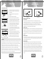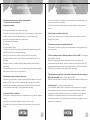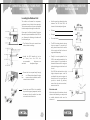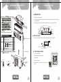
1
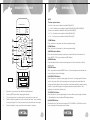
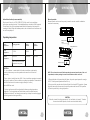
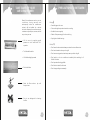
Warranty Registration System
Help us to serve you better by registering
your product for Warranty
Web
Register at www.onida.com
Telephone
Call Centre No. 0XX-39889000(0XX-STD Code of
State Capital)
Post / Visit
Post the Warranty Registration Card & Service Centre
Copy or Visit the Nearest Service Centre.
Model: INV18SMT7 / INV18SMT-S7
As per Government of India’s E-Waste (Management and Handling)
Rules, 2011(effective from May 1st, 2012) the product purchased by you
is to be considered as E-Waste and cannot be disposed off with your
general household waste. It should be disposed of through the company’s
collection center so as to prevent any damage to environment
Collection Center address
Mirc Electronics Ltd.Village Kudus,Bhiwandi Wada road,
Taluka Wada., Dist. Thane - 421312,Tel no. 952525 220375/377
Visit at : www.onida.com for details about collection Centers.
We request you to make a note of the above details and support us
in our endeavour to ensure an environmental friendly nation.
AIR CONDITIONERS
The unit displayed is for representational purposes only. Actual unit may vary.
Dear customer
Congratulation on buying ONIDA Air Conditioner.
Your Air Conditioner comes with ONIDA Guarantee of Quality
as detailed in the manual.
ONIDA takes great pride in providing its customers with stateof-the-art products that adheres to international quality
standards.
ONIDA is committed to following quality policy laid by our
chairman and managing director Mr. G. L. Mirchandani.
“We are committed to quality and strive for continuous
improvement through innovation and human development to
give customer better value for money always”
ONIDA stands committed to provide the ultimate customer
satisfaction, as nothing brings us greater joy than having
satisfied customers of ONIDA.
At ONIDA, feedback and suggestions based on your product
usage experience is greatly appreciated.
Please contact to us at [email protected]
G. Sundar
Chief Executive Officer
IMPORTANT :
Please read this owner’s manual carefully and thoroughly
before installing and operating your room air conditioners.
Please retain this owner’s manual for future reference after
reading it thoroughly.
CONTENTS
Salient Features
1
Inside Overview
2
Indoor Unit Display
3
Remote Overview
4
Operations
5
Operation Instructions
9
Operation Tips
10
General Instructions for Installation
13
Installation Sketch
16
Installation
17
Take care of your Air Conditioner
20
Precautions to be taken
21
Trouble Shooting Chart
22
Installation and Satisfaction Report
23
Warranty Terms & Conditions
25
Preventive Maintenance Service Coupon
27
Warranty Card(Customer Copy)
29
Warranty Card(service Center Copy)
31
SALIENT FEATURES
Model Code :INV18SMT7 / INV18SMT-S7
• Aesthetics:a) Unique Smart Model with High EER
b) Sleek Indoor Unit
• Performance:a) Imported High BTU Tropicalised Compressor
b) Trapezoidal Inner Grooved Tube
c) Large L - Shaped Condenser Coil
d) High RPM Fan Motor with High Static
• Features:a) Clean Air
b) Multi-Step Air Swing for Customized Cooling
c) Surround Air
d) Turbo
• Safety & Reliability:a) Hydrophilic Fins
b) Full Function LCD Remote
c) Special Insulation on the Air Vent
d) 5-Stage Epoxy Polyester Painting
1
INSIDE OVERVIEW
n
INDOOR UNIT DISPLAY
Display on the indoor unit.
INDOOR UNIT
For the icon of LED windows, only relevant icons will light up with their displays on.
Return warm Air in
Signal receiver
Front panel
(A)
Conditioned Air out
Display
Signal receiver
SET TEMPERATURE( C)
TURBO
HIGH
MED
LOW
AUTO
COOL
DRY
FAN
TEMP
MODE
ON/OFF
SWING
ENERGY
SAVER
FAN
TIMER ON/OFF
TURBO RESET LOCK
i-Cool
CLEAN
AIR
SELF
CLEAN
SLEEP/
DISPLAY
FOLLOW
ME
Remote controller
(B)
n
OUTDOOR UNIT
Air in
Connection
pipe and
connecting wire
Operation
OPERATION indication lamp This lamp illuminates when the air
conditioner is in operation.
Defrost
DEFROST indication lamp(For reverse cycle model only):
Lights up when the air conditioner starts defrosting automatically
or when the warm air control feature is activated in heating
Temp
DIGITAL DISPLAY indication lamp Displays the current setting temperature.
When the air conditioner is in FAN ONLY operation, itdisplays the actual room
temperature. When SELF CLEAN feature is activated, it displays
.
Ser timer
TIMER indication lamp
Lights up during Timer operation.
Exhaust Air
2
3
OPERATIONS
REMOTE OVERVIEW
NOTE:
*Indicates optional button.
。
SET TEMPERATURE ( C)
14 and 15 buttons are not available for Models RG51M2/(C)E.
AUTO
FAN
COOL
HIGH
DRY
MED
15 button is not available for Models R51M/(C)E and R51M/BG(C)E.
HEAT
LOW
4 ,6 ,7 ,14 ,15 buttons are not available for Models RG51M9/(C)E.
7 , 14 and 15 buttons are not available for Models RG51M3/(C)Eand RG51M3/BG(C)E.
6 ,7 ,14 ,15 buttons are not available for Models RG51M8/(C)E.
TEMP
1
MODE
ON/OFF FAN SPEED
3
4*
SWING
5
6*
SLEEP
RESET LOCK
AIR
DIRECTION
CLEAN
AIR
TIMER ON
TIMER OFF
LED
DISPLAY TURBO
7*
2
9
1)TEMP Button :
8
2)TEMP Button :
Push this button to decrease the indoor temperature setting.
Push this button to increase the indoor temperature setting .
10
11
12
3)MODE Selection Button:
Each time the button is pressed, the operation mode is shifted in the direction of the
arrow: (NOTE: COOL only model has no HEAT feature.)
13
4)SWING Button:
14*
Push this switch button to activate auto swing feature of the horizontal louver. Push it
15*
again to stop.
5)RESET Button:
When you press the recessed RESET button, all current settings are cancelled and the
control will return to the initial settings.
6)AIR DIRECTION Button:
Press this button to change the swing angle of the louver. The swing angle of the louver
BACK VIEW
is 6o for each press. When the louver swing at a certain angle which would affect the
cooling and heating effect of the air conditioner, it would automatically change the swing
direction . No symbol will appear in the display area when press this button. (Not
applicable to units without this function).
1.
Open back cover and put 2 Nos. AAA size alkaline batteries.
7)LED DISPLAY Button:
2.
Short one RESET piece after changing the batteries.
Press this button to clear the digit display in the air conditioner, press it again to activate
3.
The remote signal can be reached upto six metres from the indoor unit.
it (Not available for the units without LED display window).
4.
When the button is pressed on remote, indoor unit will “beep” once, indicating
the receipt of signal. If no “beep” sound is heard, press the button once again.
Used to select the Fan Speed in four steps- AUTO, LOW, MED or HIGH. Each time the
Remove batteries if remote control has not been used for long time..
button is pressed, the fan speed mode is shifted.
5.
8)FAN SPEED Button:
4
5
OPERATIONS
REMOTE OVERVIEW
9)ON/OFF Button:
Special function
Push this button to start operation, push the button again to stop operation.
CLEAN AIR function(on some models)
10)TIMER ON Button:
Improving the quality of indoor air is one of the mission of an air conditioner. This air
Press this button to initiate the auto-on time sequence. Each press will increase the auto-
conditioner is equipped with ionizer or Plasma Dust Collector(Depending on specific
timed setting in 30 minutes increments. When the setting time displays 10, each press
configuration of the model). With the anions generated by Ionizer, the air circulation
will increase the auto-timed setting 60 minutes increments. To cancel the auto-timed
of the air conditioner fills the room with refreshing, natural and healthy air. The Plasma
program, simply adjust the auto-on time to 0.0.
Dust Collector generates an high voltage ionization zone, through which the air is
11)SLEEP Button:
converted to plasma. Inside the air most of the dust, smoke, and pollen particles are
Press this button to go into the Energy-Saving operation mode. Press it again to cancel.
captured by the electrostatic filter.
This function is only can be used on COOL, HEAT and AUTO mode and maintain
themost comfortable temperature for you.
SELF CLEAN function
12)TIMER OFF Button:
§
Function used after the Shut Down of cooling operation to clean the
Evaporator and keep it as fresh for the next operation.
§
The unit will operate as following sequence :
Press this button to initiate the auto-off time sequence. Each press will increase the autotimed setting in 30minutes increments. When the setting time displays 10, each press will
increase the auto-timed setting 60 minutes increments. To cancel the auto-timed
FAN ONLY mode at Low fan speed--Heating operation with LOW fan
speed(applicable to cooling& heating modles only) ---FAN ONLY operation-Stop Operation---Turn off. This function is only available under COOL(AUTO
COOL, FORCED COOL) and
program, simply adjust the auto-off time to 0.0.
13)LOCK Button:
When you press the recessed LOCK button, all current settings are locked in and the
remote controller does not accept any operation except that of the LOCK. Press again to
§
cancel the LOCK mode.
DRY mode.
Before select the function, it is recommended to run the air conditioner under
14) TURBO Button:
Push this button to activate/cancel the Turbo function which enables the unit to reach the
preset temperature in the shortest time. On cooling mode, the unit will blow strong
cooling air with super high fan speed. On heating mode (applicable to the unit adopts
PTC only), the PTC will bring fast heating operation.
§
Cooling operation for about half an hour. Once the Self Clean function is
activated, all TIMER setting will be cancelled.
§
During Self Clean operation, when press the SELF CLEAN button on the
remote controller again will stop the operation and turn off the unit
automatically.
15) CLEAN AIR Button(on some models):
When push this button, the Ionizer or Plasma Dust Collector(depending on models) is
energized and will help to remove pollen and impurities from the air.
4
5
OPERATIONS
OPERATIONS
Manual operation
Manual operation can be used temporarily in case the remote controller is disable or
maintenance necessary.
Anti-mildew function(on some models)
When turns off the unit on COOL, DRY, AUTO (Cool) mode, the air conditioner
will continue operating for about 10 minutes(depending on models) at LOW fan speed.
This will help to dry up the condensed water inside the evaporator, and prevent the
breeding of mildew. Under Anti-mildew operation, do not restart the air conditioner until
the unit is completely off.
Operating temperature
AUTO/COOL
Manual control
Mode /
Temperature
Cooling operation
Room
temperature
Outdoor
temperature
Heating
operation
Drying
operation
≥17°C
≤30°C
>10°C
0°C~50°C
-15°C~30°C
0°C~50°C
button
(1)
Suspension bars
AUTO/COOL
(-15°C~50°C For the models with
low temperature cooling system)
Manual control
button
CAUTION:
1. If air conditioner is used outside of the above conditions, certain safety
protection features may come into operation and cause the unit to function
abnormally.
(2)
NOTE: The unit must be turned off before operating the manual control button. If the unit
is operational, continue pressing the manual control button until the unit is off.
2. Room relative humidity less than 80%. If the air conditioner operates in excess of
this figure, the surface of the air conditioner may attract condensation. Please sets the
vertical air flow louver to its maximum angle (vertically to the floor),
and set HIGH fan mode.
1) Grasp both sides of the panel and pull it down, the panel opened upward to an angle
of 15O . Push the panel upward and then lift it up.
2) One press of the manual control button will lead to the forced AUTO operation. If press
the button twice within five seconds, the unit will operate under forced COOL operation.
3) Close the panel firmly to its original position.
3. Optimum performance will be achieved within these operating temperature.
Suggestion: For the unit adopts an Electric Heater, when the outside ambient
temperature is below 0°C, we strongly recommend you to keep the machine plugged
in order to guarantee it running smoothly.
CAUTION:
This button is used for testing purposes only. You had better not choose it. To restore
the remote controller operation, use the remote controller directly.
6
7
OPERATING
INSTRUCTIONS
OPERATIONS
Airflow direction control
SLEEP
Ÿ Adjust the air flow direction properly otherwise, it
operation
7 hours timer off
SLEEP
operation
7 hours timer off
might cause discomfort or cause uneven room
Ÿ Adjust the horizontal louver using the remote
1 hour
controller.
Range
Ÿ Adjust the vertical louver manually.
1 hour 1 hour
Heating
How the air conditioner works
Perform this function while the unit is in operation.
AUTO operation
Use the remote controller to adjust the air flow
When you set the air conditioner in AUTO mode, it will automatically select cooling,
direction. The horizontal louver can be moved at
heating(cooling/heating models only), or fan only operation depending on what temperature
a range of 6O for each press, or swing up and
you have selected and the room temperature. The air conditioner will control room
down automatically. Please refer to the remote
temperature automatically round the temperature point set by you. If the AUTO mode is
controller operation manual for details.
uncomfortable, you can select desired conditions manually.
To set the horizontal air flow direction (left - right)
SLEEP operation
Move the vertical louver manually to adjust the air
When you push SLEEP button on remote controller during cooling, heating(cooling & heating
flow in the direction you prefer.
models only), or AUTO operation , the air conditioner will automatically increase (cooling) or
Ÿ IMPORTANT: Before adjusting the vertical louvers,
decrease (heating) per hour for the first 2 hours, then hold steady for the next 5 hours, after
the supply power must be disconnected. For some
that it will switch off. This characteristic maintains both enery saving and comfort in night
models, the vertical louver can be adjusted by
operation.
using the remote controller. Please refer to the
Range
1 hour
Cooling
Ÿ To set the vertical air flow (Up--Down) direction
Vertical
louver
Set
Temperature
Set
Temperature
temperatures.
DRYING operation
Remote controller operation manual for details.
The fan speed will be automatically controlled under dry operation. During the dry operation, if
the room temperature is lower than 10°C, the compressor stops operation and restarts until
CAUTION
the room temperature is above 12°C.
Do not operate the air conditioner for long periods with the air flow direction set downward in cooling
Optimal operation
or dehumidifying mode. Otherwise, condensation may occur on the surface of the horizontal louver
To achieve optimal performance, please note the following: Adjust the air flow direction
causing moisture to drop on to the floor or on furnishings. Do not move the horizontal louver manually
correctly so that it is not directed on people. Adjust the temperature to achieve the highest
unless it is necessary. Always use the remote controller. When the air conditioner is started
comfort level. Do not adjust the unit to excessive temperature levels. Close doors and
immediately after it was stopped, the horizontal louver might not move for approximately 10 seconds.
windows on COOL or HEAT modes, or performance may be reduced. Use TIMER ON button
Open angle of the horizontal louver should not be set too small, as COOLING or HEATING
on the remote controller to select a time you want to start your air conditioner. Do not put any
performance may be impaired due to too restricted air flow area. Do not operate unit with horizontal
object near air inlet or air outlet, as the efficiency of the air conditioner may be reduced and
louver in closed position. When the air conditioner is connected to power (initial power), the horizontal
the air conditioner may stop running. Clean the air filter periodically, otherwise cooling or
louver may generate a sound for 10 seconds, this is a normal operation.
heating performance may be reduced. Do not operate unit with horizontal louver in closed
position.
8
9
OPERATION TIPS
OPERATION TIPS
The following events may occur during normal operation.
running. This is caused by heat expansion and cold contraction of the plastic parts in the
1. Protection of the air conditioner.
unit when the temperature is changing.
Compressor protection
A noise may be heard due to louver restoring to its original position when power is first
turned on.
The compressor can't restart for 3 minutes after it stops.
Anti-cold air (Cooling and heating models only)The unit is designed not to blow cold air
4. Dust is blown out from the indoor unit.
on HEAT mode, when the indoor heat exchanger is in one of the following three
This is a normal condition when the air conditioner has not been used for a long time or
situations and the set temperature has not been reached.
during first use of the unit.
A) When heating has just starting.
B) Defrosting.
5. A peculiar smell comes out from the indoor unit.
C) Low temperature heating.
This is caused by the indoor unit giving off smells permeated from building material, from
The indoor or outdoor fan stop running when defrosting (Cooling and heating models
furniture, or smoke.
only). Defrosting (Cooling and heating models only)
Frost may be generated on the outdoor unit during heat cycle when outdoor
6. The air conditioner turns to FAN only mode from COOL or HEAT (For cooling and
temperature is low and humidity is high resulting in lower heating efficiency of the air
heating models only) mode.
conditioner.
When indoor temperature reaches the temperature setting on air conditioner, the
During this condition air conditioner will stop heating operation and start defrosting
compressor will stop automatically, and the air conditioner turns to FAN only mode. The
automatically.
compressor will start again when the indoor temperature rises on COOL mode or falls on
The time to defrost may vary from 4 to 10 minutes according to the outdoor temperature
HEAT mode (For cooling and heating models only) to the set point.
and the amount of frost build up on the outdoor unit.
7. Dripping water may generate on the surface of the indoor unit when cooling in a
2. A white mist coming out from the indoor unit
high relatively humidity (relative humidity higher than 80%).
A white mist may generate due to a large temperature difference between air inlet and
Adjust the horizontal louver to the maximum air outlet position and select HIGH fan speed.
air outlet on COOL mode in an indoor environment that has a high relative humidity.
A white mist may generate due to moisture generated from defrosting process when
8. Heating mode (For cooling and heating models only)
the air conditioner restarts in HEAT mode operation after defrosting.
The air conditioner draws in heat from the outdoor unit and releases it via the indoor unit
during heating operation. When the outdoor temperature falls, heat drawn in by the air
3. Low noise of the air conditioner
conditioner decreases accordingly. At the same time, heat loading of the air conditioner
You may hear a low hissing sound when the compressor is running or has just stopped
increases due to larger difference between indoor and outdoor temperature. If a
running.
comfortable temperature can't be achieved by the air conditioner, we suggest you use a
This sound is the sound of the refrigerant flowing or coming to a stop.
supplementary heating device.
You can also hear a low "squeak" sound when the compressor is running or has just
stopped
10
11
GENERAL INSTRUCTIONS FOR
INSTALLATION
OPERATION TIPS
Locating the indoor and outdoor units
properly will help optimise the performance of
your airconditioner. While your Onida /
Dealer's Technician will be happy to guide you
on the best location for your airconditioner,
here are a few helpful hints.
9. Auto-restart function
Power failure during operation will stop the unit completely.
For the unit without Auto-restart feature, when the power restores, the OPERATION
indicator on the indoor unit starts flashing. To restart the operation, push the ON/OFF
button on the remote controller. For the unit with Auto-restart feature, when the power
restores, the unit restarts automatically with all the previous settings preserved by the
memory function. For some models, the machine is special designed with Auto-restart
Locating the Indoor Unit
function for the open angle of the horizontal louver. Power failure during operation or
• Locate the IDU for the best cool air
circulation. Preferably, there should be
no obstructions nearby, as shown in the
adjacent figure.
pressing the ON/OFF button on the remote controller will stop the unit completely. When
the power restores or pressing the ON/OFF button on the remote controller again, the unit
restarts automatically with all the previous settings including the open angle of the
horizontal louver by the memory function. So we strongly suggest that the open angle of
the horizontal louver should not be set too small, in case the condensed water forms and
drops from the horizontal louver. Press the AUTO/COOL button under the front panel and
the open angle of the horizontal louver will be restored to the standard angle when the
condensed water forms on the horizontal louver.
• Do not locate the unit directly opposite a
door which is opened frequently. The
cold air will go out of the room each time
the door is opened, as shown in the
adjacent figure.
10. Lightning or a car wireless telephone operating nearby may cause the unit to
malfunction. Disconnect the unit with power and then re-connect the unit with power
again. Push the ON/OFF button on the remote controller to restart operation.
• All indoor units will form condensate water.
Please ensure that the condensate can
be drained out of the room to a toilet /
pantry, etc. The installation engineer will
make sure that a "U" bend is provided in
the drain to prevent insects from coming
into the room through the drain tube, as
shown in the adjacent figure.
12
13
GENERAL INSTRUCTIONS FOR
INSTALLATION
GENERAL INSTRUCTIONS FOR
INSTALLATION
Locating the Outdoor Unit
• Avoid long and complicated routing
between the IDU and ODU, as
shown in the three adjacent figures.
The outdoor unit houses the compressor,
condenser fan and electrical components.
The heat removed from the room is expelled
to the atmosphere through the outdoor unit.
• Too long
Once again, the Onida / dealer's Technician
will ensure optimal installation of the ODU for
you. However, the following information will
be of interest to you.
• Too high
• Too many bends
• The Outdoor Unit can be mounted on a
wall, sunshade or skirting.
• The ODU must be placed on strong
frame or support. If mounted on a
wall, please ensure that the wall is
thick enough and that the frame is
supported adequately.
• Ideally, the ODU should not be too
far a w a y f r o m t h e I D U ; t h e
recommended
distances are
marked in
the adjacent figure.
• Finally, it is most important for the
ODU to be easily accessible to the
service engineer. It is advisable to
discuss the same with the engineer
before deciding upon the location of
the unit.
If the ODU is to be located on a high
ledge, adequate space must be
provided for the service engineer to
service the unit. It is a good idea to
provide a catwalk (a platform)
around the unit and access door /
window to the Unit.
• Ensure that air can pass freely through
the
unit. Please allow at least 2 meters
free
space on the air outlet side, and 0.3
meters on the air inlet side.
• If more than one ODU is to be installed,
they must be properly separated, so that
the warm air from the outlet of one does
not enter the inlet of the other.
Electrical outlet
After the location of the outdoor unit and
indoor unit is finalised, you must provide
a suitable electrical outlet near the
indoor unit.
14
To
O
DU
DU
O
To
MCB
STABILISER
15
INSTALLATION
INSTALLATION SKETCH
3
15c
n
2
15cm abov
ml
e
eft
INDOOR UNIT
1. Fitment of mounting plate
1
The mounting plate should be fitted on the structural part of wall on which indoor unit
is to be installed.
2. Drill two holes at a distance of 450 mm between them for the expansion bolts.
150mm or more to ceiling
Left rear side
refrigerant
pipe hole 65
Air F
ilter
n
6.35(12000Btu/h)
Liquid Side
Connecting
12.7(12000Btu/h)
Gas Side
Pipe
9.53(18000Btu/h)
Assembly Liquid Side
16.0(18000Btu/h)
Gas Side
Remote Controller
Self-tapping Screw B ST3.9X10
Remote Controller Holder
6
Additional drain pipe
A
1
2
1
Align Ruler with straight line
mab
Wrapping tape
HEALTH
HIGH
MED
LOW
9
ADJUST
SWING
SLEEP
TIMER ON
CLEAR
AIR
RESET LOCK
TIMER OFF
Terminal board
e
bov
and fastener
3. Connect the cable
Mounting screw B
ST2.9x10-C-H
SET TEMPERATURE( C)
ON/OFF FAN SPEED
Connecting of cables
2. Dismantle the electric box cover
Air Outlet
ove
n
1. Open the front panel
Remote Controller
MODE
18
Center of Hole(Ø65mm)
Insert Ruler
ma
AUTO
COOL
DRY
HEAT
Confirm the position of holes and drill holes of diameter 65 mm on the wall
10
30c
7
Right rear side
refrigerant
pipe hole 65
Drill on the wall
Parts You
Must
Purchase
30c
120mm or more
to wall
180mm
60cm above
7
8
9
90
995
Q’ty
1
8
8
1
1
Name of Accessories
Installation Plate
Clip Anchor
Self-tapping Screw A ST3.9X25
Seal
Drain Joint
45
45
293
120mm or more
to wall
Number
1
2
3
4
5
Installation plate
Indoor unit outline
right
45
15cm
8
e
bov
B
a
0cm
Loop the
connective
cable.
20
60c
ma
AUTO FOLLOW
LED
ME
CLEAN
DISPLAY TURBO
Remote controller
holder
4. Reassemble the fastener and electric box
cover.
bov
e
Blue
Yellow-green
Black
Power connection wire
C
16
17
INSTALLATION
INSTALLATION
Discharge the air of the units:
n Installation of indoor unit
n
After putting the pipe assembly through
the wall, attach the indoor unit to the
mounting plate on the wall as shown in
the figure.
It can used as vaccum pump.
Liquid closing valve
Liquid connecting pipe Cap
Remove screw cap of closing valve and
Allen Wrench
gas charging hole; Open the closing valve Gas closing
valve
with Allen wrench(turn 90 clockwise),
Gas connecting
pipe
then push the gas hole for about 10 seconds,
(When a gas like fog appears, it indicates
Screw Cap
that the air of unit has been discharged)
put back the screw cap of gas charging hole.
Gas
Charging
Do the leak test with leak detector or soap water.
1 2(N) 3 4
n Installation of outdoor unit
Screw Cap
1
Hole
2(N)
n
Add refrigerant
• If the connecting pipe is longer than 7 meters, add refrigerant as needed. Add
amount A= (Lm-7m) 15g/m.
(A: add refrigerant amount, L: the length of connecting pipe)
• The connecting cables must be clipped together.
the length of connecting pipe (m)
7
8
9
10
• Special cable to be used to connect indoor unit and outdoor unit.
add amount (g)
0
15
30
45
• The electric box cover must be mounted on its position on outdoor unit.
• Add refrigerant with the spring balance, as specified above.
n Connecting of pipes
connecting pipe
Pipe
Diameter of pipe
Torque (N • m)
Liquid pipe
6.35 mm (1.0T)
13.7--17.6
Gas pipe
Liquid pipe
12.7 mm (1.0T)
9.52 mm (1.5T)
49.0--56.4
13.7--17.6
Gas pipe
16 mm (1.5T)
49.0--56.4
Indoor unit
Liquid pipe
Closing valve
Outdoor unit
Gas pipe
Gas charging hole
Bottle’s valve of storage refrigerant
Bottle of storage refrigerant
n Sealing the wall hole and clamping the pipe
n
• Use putty to seal the wall hole.
• Use pipe fastener to clamp the pipe on wall
Fixing Hook
Gas side piping
Liquid side piping
Mounting Board
Gas side
piping insulation
Mounting Board
External connection
electric wire
air proof with putty
Finally wrap it
with tape
Liquid side
piping insulation
Test
• Proceed leak test (with leak detector or soap water.) and inspect connecting
cables before test operation.
Test procedure: (Control by emergency operation switch or remote
controller) For detailed operation, see OPERATION OF AIR CONDITIONER
in the manual.
Water
drainage
pipe
18
19
TAKE CARE OF YOUR
AIR CONDITIONER
PRECAUTIONS TO BE TAKEN
Most of the maintenance work on your air
c o n d i t i o n e r, d u r i n g w a r r a n t y a n d
subsequently under the maintenance
contract, will be handled by a trained
technician. However, there are some simple
maintenance jobs that you, as a user, should
carry out on your own.
Do's (
)
• Seal all air gaps in the room
• Choose the right temperature to avoid over cooling
• Ventilate the room regularly.
• Switch off the power supply if not in use for long.
• Unplug the unit while cleaning.
• Lift the cover by applying gentle
pressure on both sides and lift it
upwards
Don't's (
X)
• Don't leave the doors and windows open when the air conditioner is on.
• Don't use hot water to clean your front grill
• The filters will be visible
• Don't use scouring powder, harsh soaps, wax or polish on the grill.
• Don't switch on the air conditioner immediately after switching it off.
Wait for 2 minutes.
• Lift the filters slightly upwards
• Don't operate with a clogged filter
• Don't block air intake & outlet vents
• Pull out the filters
• Don't change setting unnecessarily.
• Wash the filters under a tap until
they are clean
• Do not use detergents for cleaning
the filter.
20
21
INSTALLATION & SATISFACTION
REPORT
TROUBLE SHOOTING CHART
Customer Name :
Address
Troubleshooting Tips
If one of the following faults occurs, stop the air conditioner immediately, disconnect the power
and then connect it in again. If the problem still exists, disconnect the power and contact the
nearest customer service center.
OPERATION/RUN indicator or other indicators continue flashing.
Trouble
Phone[O]
Fuse blows frequently or circuit breaker trips frequently.
[R]
Unit Model
Unit Serial Number
Dealer Name
Invoice Number
Date of Purchase
Date of Installation
Other objects or water fall into the air conditioner.
The remote controller won't work or works abnormally.
If one of the following code appears on the display area :
E0,E1,E2,E3.....or P0,P1,P2,P3......
Malfunctions
Cause
Wait for power to be restored.
MCB Rating
Current (Amps.)
Unit may have become unplugged.
Check that plug is securely in wall
receptacle.
Cable Size
Ambient Temp. ( OC)
Fuse may have blown.
Replace the fuse.
Earthing
Room Temp. (OC)
Battery in Remote controller may
have been exhausted.
Stabiliser
Grill Temp. (OC)
Replace the battery.
Input Voltage
Remote Operation
The time you have set with timer
is incorrect.
Wait or cancel timer setting.
Unit not cooling
Inappropriate temperature
Set temperature correctly. For
or heating
setting.
detailed method please refer to
Unit does not
start
Power cut
What should be done?
Customer's Response : To be filled up by the Customer
"Using remote control" section.
(Cooling/ heating
models only)
Air filter is blocked.
Clean the air filter.
room very well
Doors or Windows are open.
Close the doors or windows.
while air flowing
Air inlet or outlet of indoor or
outdoor unit has been blocked.
Clear obstructions away first, then
restart the unit.
out from the air
conditioner
1. Installation completed within:
12hrs( ), 24 hrs( ) , 36 hrs ( ), more than 36 hrs ( )
2. How did you find the behavior of the Engineer :
Excellent ( J ), Good ( K ), Not satisfied ( L )
3. Overall rating of the service:
Excellent ( J ), Good ( K ), Not satisfied ( L )
4. Suggestion if any:
Compressor 3 minutes
protection has been activated.
Wait.
Job Number
If the trouble has not been corrected, please contact a local dealer or the nearest customer
Engineer's Signature
Customer's Signature
service center. Be sure to inform them of the detailed malfunctions and unit model.
Notes: Do not attempt to repair the unit yourself.
Always consult an authorised service provider.
22
23
WARRANTY TERMS
AND CONDITIONS
M/S. MIRC ELECTRONICS LTD, WARRANTS THIS ONIDA AIR CONDITIONER[(except the front grill,
knobs, remote unit and add-on plastic parts) TO THE ORIGINAL PURCHASER TO BE FREE FROM
DEFECTS IN MATERIALS AND WORKMANSHIP WITHIN ONE YEAR FROM THE DATE OF PURCHASE
AS PROVIDED IN THE WARRANTY REGISTERATION CARD.
WARRANTY FOR COMPRESSOR:
MIRC ELCTRONICS LTD, HEREAFTER WARRANTS TO THE PURCHASER OF THIS ONIDA AIR
CONDITIONER THAT FOR A PERIOD OF SIXTY MONTHS FROM THE DATE OF INVOICE .
WE WILL REPAIR/REPLACE THE COMPRESSOR WHICH PROVES UPON INSPECTION BY US OR ANY
OF OUR AUTHORISED SALES DEALERS TO HAVE BEEN DEFECTIVE DUE TO MANUFACTURING
DEFECT.
This warranty is subject to terms and conditions as mentioned below:
24
1.
This warranty shall be valid only for the said period of 12 months as specified above, irrespective of
whether the said unit has been in use or not for any reason whatsoever, or the unit is moved from one
location to another. Warranty does not cover accessories external to the equipment.
2.
The warranty period specified above shall include time taken for repairs, replacements, break-downs,
transit time etc. No notice of expiry period of warranty will be given by the company.
3.
This warranty shall stand automatically terminated in the event of the said unit being serviced,
repaired, installed, de-installed, re-installed or otherwise attended to by any person or organization or
agency or by the said purchaser himself other than the authorized representative of the company.
4.
Parts of the unit replaced or repaired under the terms of this warranty are warranted only for the
remaining period of the original warranty period.
5.
For attending any service call under this warranty beyond the municipal limits of the locality in which
the authorized representative/dealer is situated (outstation locations), all to and fro travelling and
other incidental expenses as prevailing from time to time incurred in connection with the visit of the
service personnel, technicians, etc shall be borne by the said purchaser and shall be payable in
advance. Additionally, all expenses incurred by the authorized representative /dealer in collecting the
said unit or any part thereof from such outstation locations and its return to the original location shall
be borne by the said purchaser.
6.
Any loss of refrigerant caused due to sabotage, improper handling or treatment , carelessness,
accident, fire, flood earthquake or any natural calamity any corrosive action on the original refrigerant
pipes, fittings, valves etc for whatever reasons, shall not be covered under this warranty.
7.
In the event of any change in the location of the unit during the warranty period, this warranty shall
become null and void unless the fact of the proposed change is communicated in writing to the
authorized dealer at least seven (7) days prior to the said change. On receipt of such information the
authorized dealer or any of its counterparts shall arrange for de-installation of the said unit on
chargeable basis. However, in the event of any damage occuring to the unit or to any of its parts during
the course of its transit by the said purchaser, repair or replacement, the said unit or any part thereof
damaged shall not be covered by this warranty.
25
Customer Identification
Number:
8. It shall be the absolute discretion of the company to a) effect the repairs or replacement of parts
whether at the site of installation or at any service centre, and b) have the job attended to either by the
Company's service personnel or its authorised dealer
Preventive Maintenance Service 1
______________________
9. This warranty is in the nature of and for the purpose of set forth herein above and in particular the
Company shall not in any event be liable for direct, indirect, incidental or consequential loss or
damages to either the said purchaser and /or his property or any other third party.
10. The AC is designed to operate at a range (230V +/- 10%). Any failure due to operation of the machine
beyond these limits will not be covered by the above warranty.
Date: ________
Customer Identification Number: ___________________________________________
Unit Model: ___________
Name of the customer: ____________________________________________________
Sr. No: _______________
Installation address: ______________________________________________________
________________________________________________________________________
Name of Serviceman:
Customer shall ensure that a stabilizer is installed in those areas where voltage is not available within
the warranty range (230V +/- 10%). The stabilizer should be of any reputed manufacturer, tested and
recommended by the Company.
________________________________________________________________________
______________________
Phone: _________________ Mobile: __________________ Fax: ________________
Date: ______ Time: _____
E-mail: _________________________________________________________________
Unit model: ____________________________ Serial Number: __________________
11. The purchaser should preserve the original invoice for necessary verification and produce, as and
when required.
Service report number: ___________________________________________________
12. Warranty null and void if:
i.
Preventive Maintenance Service
Sign. of Serviceman
Customer's Signature: _______________________ Name: _______________________
The Air Conditioner is not purchased from the authorized dealers of the company.
ii. The Service Centre copy of warranty card is not received within 10days of date of purchase at the
nearest Authorised Service Centre.
iii. Any damage is caused by accident, mishandling, tampering with installation, or negligence in
following instructions of the user manual issued by Company.
iv. Any damage is caused by improper electrical circuit outside the unit or by any defective electrical
supply
Customer Identification
Number:
v. At any time, during the warranty period if any part of the unit is tampered with, altered, repaired or
serviced by any unauthorized person, not being the authorized representative of the company or
its authorized dealers
Preventive Maintenance Service
Preventive Maintenance Service 2
______________________
Date: ________
Customer Identification Number: ___________________________________________
vi. The serail number of the unit or any part thereof is damaged , defaced, altered, obliterated , or
tampered with or removal for any reason whatsoever
Unit Model: ___________
Name of the customer: ____________________________________________________
viii. The unit is unauthorisedly moved from its original place of installation or re-installation
Sr. No: _______________
Installation address: ______________________________________________________
________________________________________________________________________
13. None of the employees and /or Authorized Dealers of the Company have any authority whatsoever to
vary the terms and conditions of this warranty.
Name of Serviceman:
14. This warranty shall be deemed to have been issued at Mumbai, state of Maharashtra and courts at
Mumbai shall have exclusive jurisdiction on matters covered by or following from this warranty, and
the original purchaser alone shall have cause of action arising out of the transaction.
________________________________________________________________________
______________________
Phone: _________________ Mobile: __________________ Fax: ________________
Date: ______ Time: _____
E-mail: _________________________________________________________________
Unit model: ____________________________ Serial Number: __________________
Service report number: ___________________________________________________
Sign. of Serviceman
Customer's Signature: _______________________ Name: _______________________
26
27
MIRC Electronics Limited
Warranty Card
Serial No.
Customer Copy
Customer Details
Title:
Mr
Ms
Mrs
M/s
Name:
Residence Address:
Dist:
Pin:
State:
Occupation:
Tel:(_____)
Res(:_____)
Code
Fax:
Code
Mobile No:
Email:
Product Details
Please Tick The Appropriate Product
Colour TV
Microwave Oven
B&W TV
DVD
Washing M/C.
AC
Plasma TV
Rear Projection TV
LCD TV
Dealer’s Name & Address
Model No:
Serial No
Please Refer Sticker On Back Cover Of Your Product
Purchase Date
Day
Month
Year
Signature
Bill No.
I Accept The Terms And Conditions of The Warranty
Customer Signature
Thank you for selecting a World Class product and we assure you that it will perform as per your expectations
We thank you for taking your time to complete this form. All Information Provided by You will be Kept Confidential.
(Please Fill In, Tear off, Fold and Mail this form to Reach us within 10 days of the Product Purchase.)
We welcome your Valuable Suggestions, if any, to Improve our Products and Services :
FOR OFFICE USE ONLY
Customer Code:
Branch:
Mirc Electronics Ltd.
Note: Company Will Not Be Responsible For The Loss Of This Form During Transit.
For Other Details on Our Products & Services Log On To www.onida.com
MIRC Electronics Limited
Warranty Card
Serial No.
Service Centre Copy
Customer Details
Title:
Mr
Ms
Mrs
M/s
Name:
Residence Address:
Dist:
Pin:
State:
Occupation:
Tel:(_____)
Res(:_____)
Code
Fax:
Code
Mobile No:
Email:
Product Details
Please Tick The Appropriate Product
Colour TV
Microwave Oven
B&W TV
DVD
Washing M/C.
AC
Plasma TV
Rear Projection TV
LCD TV
Dealer’s Name & Address
Model No:
Serial No
Please Refer Sticker On Back Cover Of Your Product
Purchase Date
Day
Month
Year
Signature
Bill No.
I Accept The Terms And Conditions of The Warranty
Customer Signature
Thank you for selecting a World Class product and we assure you that it will perform as per your expectations
We thank you for taking your time to complete this form. All Information Provided by You will be Kept Confidential.
(Please Fill In, Tear off, Fold and Mail this form to Reach us within 10 days of the Product Purchase.)
We welcome your Valuable Suggestions, if any, to Improve our Products and Services :
FOR OFFICE USE ONLY
Customer Code:
Branch:
Mirc Electronics Ltd.
Note: Company Will Not Be Responsible For The Loss Of This Form During Transit.
For Other Details on Our Products & Services Log On To www.onida.com
BUSINESS REPLY ENVELOPE
ONIDA CUSTOMER RELATION CENTRE
Adonis Electronics Pvt Ltd.
Onida House - II Mukund Ground Floor,
Mahal Industrial Estate, off. Mahakali Caves
Road, Andheri East, Mumbai, Maharashtra,
India - 400093