1
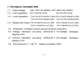
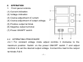
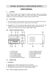
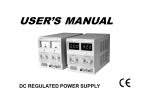
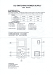
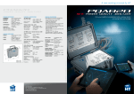
USER’S MANUAL
DC REGULATED POWER SUPPLY
DC POWER SUPPLY
BRIEF INTRODUCTION:
The HY1500 and HY1800 series variable DC power supply are very
stable, regulated DC power supplies allowing continuous adjustment of
both the output voltage and output current levels.
The HY1500 and HY1800 series have LCD displays, the HY1500C and
HY1800C have analogue displays.
MODELS:
HY1502C
HY1503C
HY1802C
HY1803C
HY1505C
HY1502D
HY1503D
HY1802D
HY1803D
HY1505D
0~15V
0~15V
0~18V
0~18V
0~2A
0~3A
0~2A
0~3A
MODEL
HY1502
HY1503
0~15V
0~15V
0~15V
0~5A
2A
3A
REGULAR
OUTPUT
VOLTAGE
REGULAR
OUTPUT
CURRENT
-1 -
1. TECHNICAL PARAMETERS
1.1 Input voltage :
104~127V AC (60Hz), 207~253V AC (50Hz)
1.2 Line regulation: CV≤0.01%+1mV
CC≤0.2%+1mA
1.3 Load regulation: CV≤0.01%+3mV(I≤3A) CC≤0.2%+3mA(I≤3A)
CV≤0.01%+5mV(I>3A) CC≤0.2%+5mA(I>3A)
1.4 Ripple and noise: CV≤0.5mVr.m.s (I≤3A) CC≤3mAr.m.s (I≤3A)
CV≤1.0mVr.m.s (I>3A)
CC≤6mAr.m.s (I>3A)
1.5 Protection: constant current and short-circuit protection
1.6 Voltage indication accuracy: LED/LCD ± 1%+2digits, analogue
display 2.5%
1.7 Current indication accuracy: LED/LCD ± 2%+2digits, analogue
display 2.5%
1.8 Environment: 0 ~ +40 0C relative humidity:<90%
-2 -
2. OPERATION
1. Front panel controls.
(1) Current indication.
(2) Voltage indication
(3) Coarse adjustment of current.
(4) Coarse adjustment of output voltage.
(5) Positive output terminal.
(6) Negative output terminal.
(7) Power ON/OFF switch
2.2 OPERATING PROCEDURE
2.2.1 For constant voltage mode adjust controls 3 clockwise to the
maximum position. Switch on the power ON/OFF switch 7 and adjust
controls 4 to set the desired output voltage. Connect the load to the output
terminals 5 & 6.
-3 -
2.2.2 For constant current mode adjust controls 4 clockwise to the
maximum position. Adjust controls 3 anti-clockwise to the minimum
position. Switch on the power ON/OFF switch 7 and connect the load to
the output terminals 5 & 6. Adjust controls 3 to set the desired output
current.
2.2.3 For restricted current protection mode switch on the power ON/OFF
switch 7, adjust controls 3 anti-clockwise to the minimum position, adjust
controls 4 clockwise to set the desired output voltage level and then connect
the load to the output terminals 5 & 6 Adjust controls 3 clockwise to set the
output current at the desired level for restricted current protection.
!
3.
ATTENTION:
3.1 In the event of a short circuit at the output the current will limit at the
value set by the current controls, however the unit should be turned off and
the short circuit removed before continuing use.
-4 -
3.2 The mains power must be switched off before servicing and servicing
should be referred to a qualified person.
3.3 The unit should be stored in a dry and well ventilated place and the
power cord removed if storing for long periods.
4. ACCESSORIES
4.1 Power cord-------------------------------one piece
4.2 Instruction manual----------------------one piece
-5 -