1
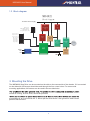
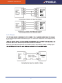
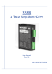
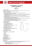
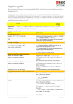
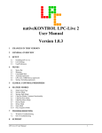
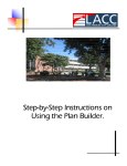
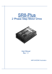
MSD4822
2 Phase Step Motor Drive
User Manual
MSD4822 User Manual
Contents
1 Introduction ............................................................................. 3
1.1 Overview ......................................................................................3
1.2 Features.......................................................................................3
1.3 Block diagram ..............................................................................4
2 Mounting the Drive ................................................................. 4
3 Connections ........................................................................... 5
3.1
3.2
3.3
3.4
Connector Diagram......................................................................5
Connecting to the Power Supply .................................................5
Connecting to a Motor .................................................................6
Connecting the Inputs and Outputs .............................................6
3.4.1 Step & Direction Inputs ........................................................................ 6
3.4.2 EN input ............................................................................................... 7
4 Switch Selecting ..................................................................... 9
4.1
4.2
4.3
4.4
4.5
4.6
4.7
Running Current ..........................................................................9
Idle Current ..................................................................................9
Microstepping .............................................................................10
Self test .......................................................................................10
Command Signal Smoothing ......................................................11
Load Inertia .................................................................................11
Digital Signal Filter ......................................................................11
6 LED Error Codes ................................................................... 12
7 Reference Materials .............................................................. 12
7.1 Mechanical Outline .....................................................................12
..............................................................................13
...................................................................... 13
............................................................. 13
2
MSD4822 User Manual
1 Introduction
Thank you for selecting the MOONS’ MSD4822 Step Motor Drive. We hope our commitment to
performance, quality and economy will make a successful motion control project.
1.1 Overview
The MSD4822 series drives are cost-effective, high performance 2 phase step drives. The design is
based on advanced digital current control technology, and features high torque, low noise, and low
vibration. The running current, microstep resolution and other parameters are switch selectable.
1.2 Features
• Power Supply - operates from a 12 to 48 volt DC power supply
• Output Power - switch selectable, 8 settings, maximum 2.2 amps peak
• Current Control - advanced digital current control provides excellent high speed torque
• Microstep Resolution - switch selectable, 16 settings: 200, 400, 800, 1600, 3200, 6400,
12800, 25600, 1000, 2000, 4000, 5000, 8000, 10000, 20000, 25000 step/rev
• Speed Range - speeds up to 3000 rpm
• Anti Resonance - raises the system-damping ratio to eliminate midrange instability and allow
stable operation throughout the speed range of the motor.
•
resonance gain settings
•
micro-steps
• Control Modes - Step & Direction or CW/CCW pulse
•
• Load Inertia Select - as part of the motor database each motor can be selected for use with
low or high load inertia.
• Idle Current - switch selectable for 50% or 90% idle running current reduction 1 second after
the motor stops
• Self Test - switch selectable, the drive will perform a 2 rev, 1 rps, CW/CCW move test
•
components from the command sequence, reducing jerk, limiting excitation of system resonance
3
MSD4822 User Manual
1.3 Block diagram
MSD4822
Block Diagram
12-48VDC Power Supply
Self Test
Smoothing Filter
Load Inertia
Step Noise Filter
Current Set 1
Current Set 2
Current Set 3
Idle Current
Step Res 1
Step Res 2
Step Res 3
Step Res 4
STEP
DIR
EN
10V
5V
switching
reg
3.3V
reg
reg
Voltage
Det.
Gate
Drivers
(4)
MOSFETs
(8)
motor
DSP
Over
Current
Det.
Optical
Isolation
Input
LED
2 Mounting the Drive
The MSD4822 Step Drive can be mounted on the wide or the narrow side of the chassis. If it is mounted
on the wide side, M3 screws should be used through the four corner holes. For narrow side
mounting applications, M3 screws can be used in the two side holes.
forced air cooling, as from a fan, should be provided.
surrounding air to be more than 40 °C. Never put the drive where it can get wet or where metal
particles can fall into it.
4
MSD4822 User Manual
3 Connections
To use the MSD4822 Step Drive, the following items are needed:
• A power supply (12 - 48 VDC)
• Pulse & Direction signal
• A compatible step motor
3.1 Connector Diagram
LED
Control Signal
Switches for selecting
Motor Connector
Power Connector
ENEN+
DIRDIR+
STEPSTEP+
SW8
SW7
SW6
SW5
SW4
SW3
SW2
SW1
BB+
AA+
VV+
Switches for selecting
SW12
SW11
SW10
SW9
Grounding screw
3.2 Connecting to the Power Supply
If the power supply does not have a fuse on the output or some kind of short circuit current limiting
device, a fast acting fuse is required. A 3 amp fast acting fuse should be installed in line with the
“+” power supply lead.
Connect the motor power supply “+” terminal to the drive terminal labeled “V+”. Connect the power
supply “-” to the drive terminal labeled “V-”.
Be careful not to reverse the wires.
5
MSD4822 User Manual
3.3 Connecting to a Motor
Red
Red/White
Red
Black
Red/White
Green
Green White Green/
White
Green/White
3.4 Connecting the Inputs
3.4.1 Step & Direction Inputs
The MSD4822 Step Drive has two high speed optically isolated inputs called STEP and DIR that accept
5 to 24 volt single-ended or differential signals, up to 2MHz. The maximum voltage that can be
applied to the input is 28V.
The motor executes one step with the falling edge of the STEP signal.
The direction of rotation is controlled by the DIR signal level. A low level signal (0 level) will result
in clockwise rotation, and a high level signal (1 level) will result in counterclockwise rotation.
6
MSD4822 User Manual
3.4.2 EN input
a 5 to 24 volt single-ended or differential signal. The maximum voltage that can be applied to the
input is 28V.
the motor will be free. When EN input is open, the drive is activated.
When the drive has encountered an error and the fault is removed from system, a falling signal
7
MSD4822 User Manual
8
MSD4822 User Manual
4 Switch Selecting
SW1
SW2
SW3
Running current
SW4
SW5
Idle current
SW6
SW7
SW8
Microstepping
SW9
SW10
SW11
SW12
Self test
Signal Smoothing
Load Inertia
Digital Signal Filter
4.1 Running Current
The output current of the MSD4822 Step Drive is set by the SW1, SW2, and SW3 switches and can be
changed as necessary. There are 8 settings available according to the ON/OFF combination of the
switches.
Peak
SW1
SW2
SW3
0.3A
ON
ON
ON
0.5A
OFF
ON
ON
0.7A
ON
OFF
ON
1.0A
OFF
OFF
ON
1.3A
ON
ON
OFF
1.6A
OFF
ON
OFF
1.9A
ON
OFF
OFF
2.2A
OFF
OFF
OFF
4.2 Idle Current
The running current of the MSD4822 drive is automatically reduced whenever
the motor hasn’t moved for 1 second. Setting the SW4 switch to ON
reduces the current to 50% of its running value. Setting this switch to OFF
maintains 90% of the running current. This 90% setting is useful when a
high holding torque is required. To minimize motor and drive heating it is
highly recommended that the idle current reduction feature be set to 50%
unless the application requires the higher setting.
9
4
4
ON
50%
OFF
90%
MSD4822 User Manual
4.3 Microstepping
The microstep resolution is set by the SW5, SW6, SW7, and SW8 switches. There are 16 settings.
Microstep(step/rev)
SW5
SW6
SW7
SW8
200
ON
ON
ON
ON
400
OFF
ON
ON
ON
800
ON
OFF
ON
ON
1600
OFF
OFF
ON
ON
3200
ON
ON
OFF
ON
6400
OFF
ON
OFF
ON
12800
ON
OFF
OFF
ON
25600
OFF
OFF
OFF
ON
1000
ON
ON
ON
OFF
2000
OFF
ON
ON
OFF
4000
ON
OFF
ON
OFF
5000
OFF
OFF
ON
OFF
8000
ON
ON
OFF
OFF
10000
OFF
ON
OFF
OFF
20000
ON
OFF
OFF
OFF
25000
OFF
OFF
OFF
OFF
4.4 Self test
Setting switch SW9 to ON after the drive is powered up will cause the drive
to perform a self test move of 2 revolutions both CW and CCW at 1rps.
Setting switch SW9 to OFF will disable this feature.
9
ON
10
9
OFF
SELF TEST
MSD4822 User Manual
4.5 Command Signal Smoothing
Setting switch SW10 to ON selects this function; setting it to OFF will disable
it. Command signal smoothing can soften the effect of immediate changes in
velocity and direction, making the motion of the motor less jerky. An added
advantage is that it reduces wear on mechanical components.This function
can cause a short delay in following the control signal, and should be used
with that in mind.
10
10
ON
OFF
Command Signal
Smoothing
4.6 Load Inertia
11
ON
High
11
Switch SW11 selects the load inertia. Set it to ON for high inertia
applications and to OFF for low inertia applications. The load inertia
selection can help the MSD4822 drive to calculate the current control parameter,
which is used in Anti-Resonance. If the load inertia is close to that of the
motor rotor, select the low (OFF) setting. If the load inertia is higher than
that of the motor rotor, select the high (ON) setting.
OFF
Low
Load Inertia
4.7 Digital Signal Filter
system works on the low microstep, select the 150 KHz (ON) setting. If the
system works on the high microstep, select the 2 MHz (OFF) setting.
12
12
ON
OFF
150 KHz
2MHz
Digital Signal
11
MSD4822 User Manual
6 LED Error Codes
The MSD4822 Step Drive has one bicolor (red/green) LED to indicate status. When the motor is
Code
Error
Solid green
Motor disabled
Flashing green
Motor enabled
3 red,1 green
Over temperature
3 red,2 green
Bad internal voltage
4 red,1 green
Over voltage
4 red,2 green
Under voltage
5 red,1 green
Over current/short circuit
6 red,1 green
Open motor winding
7 Reference Materials
7.1 Mechanical Outline
13
2-3.5
5
56
21
2-4.5
87.5
M3
85.5
92.5
Unit:mm
12
MSD4822 User Manual
Parameter
Min.
Typ.
Max.
Unit
Power Supply
12
-
48
VDC
Output Current (Peak)
0.3
-
2.2
Amps
STEP/DIR Input Signal Average Forward Current
6
10
15
mA
Step Frequency
2
-
2M
Hz
STEP Minimum Pulse Width Hi and Low
250
-
-
ns
DIR Minimum Pulse Width
50
-
-
us
Under Voltage Protection
-
10
-
VDC
Over Voltage Protection
-
52
-
VDC
4.0
-
28
VDC
-
-
2.5
S
Input signal Voltage
Driver Initialization time
Heat Sinking Method
Natural cooling or fan-forced cooling
Surrounding Air Conditions
Avoid dust, oily mist and corrosive air
Operating Temperature
0 - 40°C (32 - 104°F)
Maximum Ambient Humidity
90% non-condensing
Shock
5.9m/s² maximum
Storage Temperature
-10 - 70°C (14 - 158°F)
敏石系統有限公司
www.montrol.com.tw
330桃園市同德11街58號10樓之2
tel: 03-358-6008
e-mail: [email protected]
13
fax: 03-358-6009