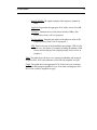
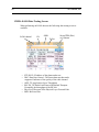
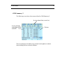
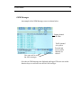
1
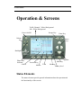
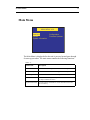
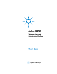
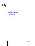
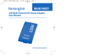
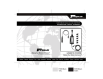
ZK-SAM, ZK-SAMp, ZKMPS
User Manual
ZK Celltest, Inc.
256 Gibraltar Drive
Suite 109
Sunnyvale, CA 94089
(Tel) 408.752.0449 (Fax) 408.752.0477
Web: www.zk.com
e-mail: [email protected]
Release Version: 9.0
Log Format Version 6.14
Release Date: January 26, 2007
ZK Celltest - User Manual
Table of Contents
Installation ....................................................................................................1
Configurations ..............................................................................................3
Features Table .......................................................................................................3
Compatible Phones ...............................................................................................3
Quick Start ....................................................................................................4
Voice Call Testing .................................................................................................4
Data Call Testing ..................................................................................................4
ZK-SAM ................................................................................................................5
ZK-SAMp ..............................................................................................................5
ZK-MPS .................................................................................................................5
Quick Start ....................................................................................................6
Voice Call Testing .................................................................................................6
Data Call Testing ..................................................................................................6
Operation & Screens ....................................................................................7
Status Elements .....................................................................................................7
Compact Flash Memory Card ....................................................................8
Phone 1, 2, 3, 4 and 5 Indicators ................................................................8
Removable Battery ......................................................................................8
Battery Level Indicator ...............................................................................9
Memory Indicator .......................................................................................9
Markers .......................................................................................................9
Time with GPS Available ............................................................................9
Summary of Screens ...........................................................................................10
Main Menu ..........................................................................................................11
SAM-ALL Screens ..............................................................................................12
CDMA Summary .......................................................................................12
Screen Elements ............................................................................12
EvDO Summary Screen ............................................................................14
CDMA/EAMPS Handoff ...........................................................................15
EvDO Handoffs .........................................................................................16
CDMA Message Screen ............................................................................17
CDMA EvDO Message Screen .................................................................18
PN Call Follow Screen .............................................................................19
CDMA Data Testing Screen .....................................................................19
CDMA EvDO Data Testing Screen ..........................................................20
PN Scan Screen .........................................................................................21
GSM Summary 1 .......................................................................................22
GSM Summary 2 .......................................................................................23
GSM Handoff ............................................................................................24
GSM Messages ..........................................................................................25
Confidential & Proprietary
GSM RSSI/BSIC Scanning Screen ............................................................26
GPRS/EDGE Data Testing Screen ...........................................................27
EAMPS Summary ......................................................................................28
Phone Summary ........................................................................................29
Replay ..................................................................................................................29
Audible Alerts .....................................................................................................31
Log Memory ........................................................................................................31
Configuration Menus ..........................................................................................32
Delete Log Files ........................................................................................32
Device Setup .............................................................................................32
Setting up a CDMA Phone ...........................................................33
Alerts Setup ...............................................................................................34
Setting up a CDMA Phone for Data Testing ............................................35
Data Testing: .................................................................................35
Auto Redial: ..................................................................................35
FTP Upload: ..................................................................................36
FTP Download: .............................................................................36
FTP Setup . . .: ..............................................................................36
HTTP Test: ...................................................................................36
HTTP Test Setup . . .: ...................................................................37
Link Setup . . .: ..............................................................................37
Dual-Port Setup . . .: .....................................................................38
Default Setup . . .: .........................................................................39
Setting up the Retriever Phone (PN Scanner) ..........................................39
Setting up the Comarco HPN (PN Scanner) .............................................41
Setting up a GSM Phone ...........................................................................42
Setting up a GSM phone for GPRS_EDGE Data Testing ............43
Data Testing: .....................................................................43
Auto Redial: ......................................................................44
FTP Upload: ......................................................................44
FTP Download: .................................................................44
FTP Setup . . .: ..................................................................44
HTTP Test: .......................................................................45
HTTP Test Setup . . .: .......................................................46
Link Setup . . .: ..................................................................47
Default Setup . . .: .............................................................47
Setting up the GSM Scanner Phone ..............................................48
User-defined channels for GSM Scanning .......................49
GSM/CDMA Cell Site ...............................................................................50
Global Setup .............................................................................................53
Auto Start ......................................................................................53
Auto Keylock ................................................................................53
GPS Setup . . . ...........................................................................................54
ZK Celltest - User Manual
Features . . . ..............................................................................................55
Appendix A - Cellsite File Format v4.1 1................................................A-1
Confidential & Proprietary
ZK User Manual
1
Installation
Use supplied mount and
screws to mount display
Display cable
Display
GPS
GPS Antenna
Power
PWR
Phone connections
P1/P4
P2/P5
P3/P6
+12VDC (Unswitched) - Red
Ignition Sense (Switched) - Yellow
Ground - Black
(Fuse taps and fuses included in
installation kit)
Installation: Your unit came with the fused vehicle power assembly.
Step 1 - Crimp one of the mini-fused leads to the Red (Constant Power)
wire of the Unit Power Assembly cable.
Step 2 - Crimp the other mini-fused lead to the Yellow (Ignition Sensor)
wire of the Unit Power Assembly cable.
Step 3 - Crimp the ring lug to the Black (Ground) wire of the Unit Power
Assembly cable.
Step 4 - Referring to your vehicle owner's manual locate a fuse position
with constant power for the Unit Power Assembly Red Wire.
Step 5 - Remove the existing fuse from the vehicle fuse position you
selected in Step 4 and insert it into the available fuse position in the minifused lead.
Step 6 - Insert the mini-fused lead into the vehicle fuse position you
selected in Step 4.
Step 7 - Referring to your vehicle owner's manual locate a fuse position
with ignition sensor for the Unit Power Assembly Yellow Wire.
Step 8 - Remove the existing fuse from the vehicle fuse position you
selected in Step 7 and insert it into the available fuse position in the minifused lead.
2
ZK Celltest, Inc.
Step 9 - Insert the mini-fused lead into the vehicle fuse position you
selected in Step 7.
Step 10 - Attach the Black lead of the Unit Power Assembly to a ground
surface of the vehicle.
ZK User Manual
3
Configurations
Features Table
Below is a table of the Features and Options available on each of the three
data collection products, ZK-SAM, ZK-SAMp and ZK-MPS.
Integrated Phone
Scanner scanners
Technologies
Simultaneous
phones
ZK-SAM ZK-SAMp ZK-MPS
Port 1
Port 2
Port 3
Port 4
Port 5
EAMPS Voice
CDMA Voice
GSM Voice
CDMA 2000
EvDO Rev O
GPRS/EDGE
UMTS
EvDO Rev A
HSDPA
Y
Y
Y
N
N
Y
Y
Y
Y
F
Y
Y
F
F
Y
Y
Y
Y
Y
Y
Y
Y
Y
F
Y
Y
F
F
Y
Y
Y
Y
Y
Y
Y
Y
Y
F
Y
Y
F
F
GSM/BSIC
Y
Y
Y
PN 850MHz
Y
Y
Y
PN 1900MHz
Comarco PN
Comarco GSM/BSIC
Comarco EvDO
Comarco UMTS
Portable
GPS
Y
N
N
N
N
N
Y
Y
N
N
N
N
Y
Y
Y
Y
Y
Y
Y
N
Y
Compatible Phones
Go to http://www.zk.com/support/release_info.html for an updated list of
compatible phones.
4
ZK Celltest, Inc.
Quick Start
NOTE: The Compact Flash memory card must be securely in its slot for
the unit to function properly. When removing the Compact Flash card you
must FIRST turn the unit off, otherwise you risk losing data and corrupting
the compact flash card file system.
Voice Call Testing
To get up and running right away do the following:
Step 1. Securely install the Compact Flash memory card in the unit.
Step2. After installation, turn on the phones, and turn on power.
Step 3. In the Phone Setup Screen select the correct phones for the phone
connections.
Step 4:In the Main Menu highlight SAM-ALL and press ENTER
Step 5: Use the arrow keys to change screens.
Data Call Testing
To get up and running right away do the following:
Step 1. Securely install the Compact Flash memory card in the unit
Step2. After installation, turn on the phones, turn on power.
Step 3. In the Phone Setup Screen configure for the CDMA or GSM phone
and connect the data-capable phone to the unit.
NOTE: Data testing works only when the direct connect cable is used.
Data testing will not work when the phone is connected to the
unit via the handsfree kit.
Step 4. Enable the Dual-Port Mode. See “Dual-Port Setup . . .:” on
page 38.
Step 5. Configure the Link. See “Link Setup . . .:” on page 37.
Step 6. In the Main Menu highlight SAM-ALL and press ENTER.
Step 7. Use the left/right arrow keys to change screens and go to the “Data
Test” Screen.
ZK User Manual
ZK-SAM
The vehicular only ZK-SAM can be configured with a choice of air interface technologies, phone-based scanners and up to three phone connections.
The ZK-SAM is typically used by Cellular Technicians to monitor and
troubleshoot network and cell site related problems.
ZK-SAMp
The vehicular/portable ZK-SAMp can be configured with a choice of air
interface technologies, phone-based scanners, internal 30KHz scanners and
up to five phone connections.
The portability option adds two batteries and a carrying case allowing
indoor walkaround measurements.
The ZK-SAMp is used for indoor/outdoor measurement applications and
for benchmarking.
ZK-MPS
The vehicular ZK-MPS can be configured with a choice of air interface
technologies, phone-based scanners, internal Comarco multi-technology
scanners and up to five phone connections.
The ZK-MPS is typically used by System Performance and RF Engineers
to optimize cellular networks.
5
6
ZK Celltest, Inc.
Quick Start
NOTE: The Compact Flash memory card must be securely in its slot for
the unit to function properly. When removing the Compact Flash card you
must FIRST turn the unit off, otherwise you risk losing data and corrupting
the compact flash card file system.
Voice Call Testing
To get up and running right away do the following:
Step 1. Securely install the Compact Flash memory card in the unit.
Step2. After installation, turn on the phones, and turn on power.
Step 3. In the Phone Setup Screen select the correct phones for the phone
connections.
Step 4:In the Main Menu highlight SAM-ALL and press ENTER
Step 5: Use the arrow keys to change screens.
Data Call Testing
To get up and running right away do the following:
Step 1. Securely install the Compact Flash memory card in the unit
Step2. After installation, turn on the phones, turn on power.
Step 3. In the Phone Setup Screen configure for the CDMA or GSM phone
and connect the data-capable phone to the unit.
NOTE: Data testing works only when the direct connect cable is used.
Data testing will not work when the phone is connected to the
unit via the handsfree kit.
Step 4. Enable the Dual-Port Mode. See “Dual-Port Setup . . .:” on
page 38.
Step 5. Configure the Link. See “Link Setup . . .:” on page 37.
Step 6. In the Main Menu highlight SAM-ALL and press ENTER.
Step 7. Use the left/right arrow keys to change screens and go to the “Data
Test” Screen.
ZK User Manual
7
Operation & Screens
Traffic Channel - Yellow Background
Idle - White Background
Power On/Off
Escape Key
Enter Key
Volume
Arrow
Keys
Backlight
Phone Port
Indicator
# SATS
Speaker
Shift Key
Function Keys
Marker
Time
Memory
Battery level
Status Elements
The status elements provide general information about the operation and
the functionality of the screens.
8
ZK Celltest, Inc.
Compact Flash Memory Card
A compact flash memory card is used to store log data. The units typically
ship with an extended temperature range version of these cards. If you purchase a card from another company we strongly recommend that you buy a
high quality one.
IMPORTANT: DO NOT REMOVE THE CARD WHEN THE UNIT
IS POWERED ON. ONLY REMOVE THE CARD AFTER YOU
HAVE TURNED THE UNIT OFF. CARDS LESS THAN 128MB ARE
NOT SUPPORTED.
ALSO, THE MINIMUM SIZE CARD THAT CAN BE USED IS
128MB AND THE MAXIMUM WE HAVE TESTED IS 1GB.
ONLY CF CARDS WITH FAT-16 FORMATTING ARE SUPPORTED.
Phone 1, 2, 3, 4 and 5 Indicators
There is an indicator on some screens that allows the user to switch
between phones. When the indicator is displayed in the lower left corner of
the display the user can press the up/down arrow keys to switch between
phone displays.
Removable Battery
The ZK-SAMp with the portability option comes with a removable battery.
A fully charged battery will provide approximately five to seven hours of
usage with the backlight turned off. Before removing the battery, make sure
that external power is disconnected and the unit is turned off. Loosen the
thumb screw to the battery compartment and remove the battery door. Pull
the battery cord to remove the battery.
Battery compartment
ZK User Manual
Battery Level Indicator
NOTE: Valid for portable ZK-SAMp. A battery icon is used to indicate the
current storage level of the main battery. The unit will power down when
the battery has only five-percent charge remaining.
When the battery goes below 20 percent chargeit will beep five times every
two minutes. Replace the battery with a fully charged one.
Performance Tip: A fully charged battery (two hours of charging time) typically provides five to seven hours of operation. To increase the battery life,
set the backlight to its lowest setting.
Memory Indicator
An icon is used to indicate the amount of free memory on the Compact
Flash card for data. When memory is full the data will be overwritten on a
first in - first out (FIFO) basis.
The amount of data stored is dependent on the disk space of the compact
flash card. Typically, up to 5MB of data per CDMA phone and up to 7MB
per GSM phone can be stored per hour.
Markers
Pressing the ENTER key inserts a marker into the data file for postprocessing. When a marker is entered, the “Pushpin” icon will be displayed
with the number of the marker next to it.
Time with GPS Available
The Time indicator appears on every screen. Units with GPS will display a
circle and, in the lower portion of the screen, the number of locked-in satellites.
The time is generated by an internal clock backed up by an internal lithium
battery. The average lifespan of the internal battery is ten years and must be
replaced by a factory-authorized technician.
For units with GPS receivers the internal clock is updated by GPS time (if
there is a current fix) each time the user goes into and out of the SAMALL.
9
10
ZK Celltest, Inc.
Summary of Screens
The summary table below shows all possible screens .
TABLE 1: SUMMARY OF ZK-SAM, ZK-SAM AND ZK-MPS DATA SCREENS
Screen
Name
Options Required
Description
CDMA Summary
CDMA Technology
Phone data summary of actives, top
candidates/neighbors
GSM/UMTS Summary 1
GSM Technology
Phone data summary of serving and
neighbor channels - graph
GSM/UMTS Summary 2
GSM Technology
Phone data summary of serving and
neighbor channels - table
EAMPS Summary
None
Phone data summary of serving
channeland scanning data
Phone Summary
Additional ports
Displays key data from multiple
phones on a single screen.
GSM/UMTS Handoff
GSM Technology
Serving channel and last 6 handoffs
including strongest neighbor prior to
handoff
CDMA/EAMPS
Handoff
CDMA Technology
Serving channel and last 6 hard/soft
handoffs
EAMPS scanning
screens
R8 and/or R19 CW Scanner
Scans user-defined 30KHz channels
and displays and reports the strongest
GSM Scanning
Screen
GSM Scanner
Scans GSM channels for RSSI and
BSIC
PN Call Follow
PN8 and/or PN 19
PN Scanner follows the call of
another phone and logs Missing
neighbors and Pilot Polluters
PN Channel Scanning
PN8 and/or PN 19
PN Scanner scans PNs of userdefined channels and displays and
logs the strongest
Data Testing
1xRTT, EvDO and GPRS/
EDGE Data Testing
Throughput and other data is displayed and logged on a data call
GSM Messages
GSM
Over-the-air messages
CDMA Messages
CDMA
Over-the-air messages
ZK User Manual
11
Main Menu
MAIN MENU V8.8
SAM-ALL
Utilities . . .
System Information
Configuration . . .
Firmware Updates
The Main Menu is displayed after the unit is powered on and goes through
it's start up procedure. The main menu contains the following functions:
TABLE 2:
Menu Item
Description
SAM-ALL
Live call follow, coverage and interference measuring
Firmware Updates
Information screen about software upgrade availability
Configuration
A list of menus to customize the configuration
Utilities
Screen for reformatting the Compact Flash card. Additional utilities may be added in the future.
System Information
Provides software and hardware version information and available free memory
12
ZK Celltest, Inc.
SAM-ALL Screens
The SAM-ALL data screens will appear when SAM-ALL is highlighted in
the Main Menu and the ENTER key is depressed.
CDMA Summary
Active Agg. Ec/Io
Serving Channel data (zoom line)
Hyperband
Active Set
Candidate Set
Neighbor Set
Strongest
Candidates
Neighbors
The Zoom Summary data screen is the one most commonly used because it
summarizes all the phone data collected.
Screen Elements
Zoom Line: Paging channels are shown as inverse video (light text on a
dark background). Traffic channels are shown as normal video (dark text
on a light background). The following values for the active channel appear
in the zoom line from left to right:
Hyperband Indicator: A lower case “p” indicates that the phone is
on a PCS channel; a lower case “c” indicates that the phone is
on a cellular channel.
Frequency Channel: Indicates the center frequency channel for the
CDMA channel
ZK User Manual
13
RxAGC (RSSI): The signal strength of the frequency channel in
dBm.
Agg EcIo: Represents the aggregate Ec/Io of the Active Set in dB.
Tx Power: Transmit power of the phone in units of dBm. (Displayed only when a call is in progress.)
Tx Gain Adjust: Transmit gain adjust of the phone in units of dB.
(Displayed only when a call is in progress.)
FER: Frame error rate of the downlink in percentages. FER is calculated every 100 frames (2 seconds) by taking the number of bad
frames and dividing by 100. (Displayed only when a call is in
progress.)
Table: The table shows the Active set, strongest candidates and strongest
neighbors PNs, Ec/Io and cellnames (color coded by neighbor set type).
Graph: The graph shows the aggregate Ec/Io of the Active set, strongest
candidates and strongest neighbors over a 40-second, scrolling time window (color coded by neighbor set type).
14
ZK Celltest, Inc.
EvDO Summary Screen
With the EvDO option an additional summary screen is available. Since the
EvDO phone is monitoriong both the CDMA channel and the EvDO channel an additional summary screen is provided.
EvDO channel
PN
SINR
TxPwr
Sector ID24 (hex)
or Cellname
ZK User Manual
15
CDMA/EAMPS Handoff
An example of the CDMA/EAMPS Handoff screen is shown below.
Serving Channel
Prior soft/hard
handoffs
This screen shows the last 10 soft/hard handoffs. The information displayed in the table is the last measured data just prior to the handoff.
The following describes the items in the columns:
• mm:ss - the time in minutes:seconds the handoff occurred
• Chan - Carrier frequency of the channel just prior to the
handoff
• Rssi - Received Signal Strength just prior to the handoff
• PN1 - Strongest PN of the Active Set
• PN2 thru 6 - Active Set members
16
ZK Celltest, Inc.
EvDO Handoffs
The following EvDO handoff screen is displayed when performing EvDO
testing.
EvDO channel
PN
Sector ID24 (hex)
SINR
TxPwr
or Cellname
This screen shows the last 10 soft/hard EvDO handoffs. The information
displayed in the table is the last measured data just prior to the handoff.
The following describes the items in the columns:
• mm:ss - the time in minutes:seconds the handoff occurred
• Chan - Carrier frequency of the channel just prior to the
handoff
• Rssi - Received Signal Strength just prior to the handoff
• PN1 - Strongest PN of the Active Set
• PN2 thru 6 - Active Set members
ZK User Manual
17
CDMA Message Screen
An example of the CDMA Message screen is shown below.
Current/serving channel data
Reverse link
Forward Link
Traffic channel
highlighted in yellow
Scroll up/down to see up
to 1001 messages
The CDMA message screen displays the over-the-air messages. Uplink and
downlink messages are colored. Voice channel messages are highlighted in
yellow. Parts of the Order messages are decoded.
All the messages are logged for further decoding and post-processing.
18
ZK Celltest, Inc.
CDMA EvDO Message Screen
With the EvDO option enabled an additional EvDO message screen is displayed.
EvDO channel
PN
Sector ID24 (hex)
SINR
TxPwr
or Cellname
The CDMA EvDO message screen displays the over-the-air messages.
Uplink and downlink messages are colored. Voice channel messages are
highlighted in yellow.
All the messages are logged for further decoding and post-processing.
ZK User Manual
19
PN Call Follow Screen
If the PN Scanner is set to the Call Follow mode, then the following screen
will be available for display. This screen shows the current channel information in the top row, the Active Set information just below it, and under
that one in the lower row, the Pilot Polluters and Missing Neighbors.
Active Set
Pilot
Polluters
Missing Neighbors
CDMA Data Testing Screen
With the data testing option enabled, the following screen will be available.
The throughput values are displayed in text and graphical formats. The bar
graphs are color coded based on the throughput level.
20
ZK Celltest, Inc.
CDMA EvDO Data Testing Screen
When performing an EvDO data test the following data testing screen is
available.
EvDO channel
•
•
•
•
•
•
PN
Sector ID24 (Hex)
SINR
TxPwr
or Cellname
FTP DL IP: IP address of the phone under test
DRC: Data Rate Control - The fastest data rate that can be
supported. Indicator of the quality of the radio channel.
APPL TP: Application Layer Throughput
RLP DL TP: Radio Link Protocol Downlink Throuput Essentially the throughput of the RF link.
Phys Fwd: Throuput of the Physical Layer Forward Path
BER: Bit Error Rate
ZK User Manual
21
PN Scan Screen
When the PN Scanner is set to scan user-settable channels, the following
screen is available.
Up to five CDMA carriers can be displayed on a single screen. The three
strongest PNs along with their Ec/Io are displayed for each carrier. The top
25 PNs are logged for each carrier.
If multiple PN Scanners are attached then each Scanner will be associated
with its own screen. The up/down arrow keys are used to switch between
scanners.
Strongest PNs in each carrier
Carriers
(up to 5)
The PN scanner can be programmed to scan up to 5 carriers. The top 3 PNs
in each carrier is displayed. The top 25 PNs in each carrier is logged.
22
ZK Celltest, Inc.
GSM Summary 1
The following screen shows the measured data for GSM Summary 1.
Serving channel data (zoom line)
Serving Channel
and neighbor RSSI
Serving and neighbor
channel, BSIC
and RSSI
Parameters shown are as follows:
• 6219 = channel number (ARFCN or BCCH)
• C = Time slot (0=A, 7=G)
• dBm=RSSI Sub (-92)
• BSIC (Base Station Identifier Code)=10
• CID (Cell Identity)=8513
• MAIO = 2
• PL (Mobile Transmit Power)=0
• TA (Timing Advance)=1
• RLT (Radio Link Timeout) = 32
• Q (RxQUAL Sub- Audio quality measurement)=4
• FER (Frame Error rate) = 0
• LAC (Location Area Code) = 235
ZK User Manual
23
GSM Summary 2
The following screen shows the measured data for GSM Summary 2.
Serving channel data (zoom line)
Serving Channel
and neighbor RSSI
and BSIC
Cellname
This screen displays the GSM serving channel and neighbors in tabular
form including the user-defined cellnames.
24
ZK Celltest, Inc.
GSM Handoff
An example of the GSM Handoff screen is shown below.
Paging channel
is in white
Traffic channel
is in yellow
This screen shows the last 9 handoffs. The information displayed in the
table is the last measured data just prior to the handoff.
Description of column headings:
• RSSI - Received Signal Strength just prior to the handoff
• dRSSI - delta in Received Signal Strength (Rssi after
minus Rssi before)
• BSIC- BSIC just prior to handoff
• N1 - Strongest neighbor channel just prior to handoff
• RSSI (N1) - RSSI of strongest neighbor channel just prior
to handoff
• BSIC (N1) - Color code (BSIC) of strongest neighbor
channel just prior to handoff
ZK User Manual
25
GSM Messages
An example of the GSM Messages screen is shown below.
Paging channel
is in white
Traffic channel
is in yellow
Forward and
reverse traffic
channels are
colored
User can scroll to view
last 1001 messages
Over-the-air GSM messages are displayed and logged. The user can use the
function keys to scroll and view the last 1001 mesages
26
ZK Celltest, Inc.
GSM RSSI/BSIC Scanning Screen
This screen requires the GSM RSSI/BSIC scanning option to display. The
following screen displays the GSM scanning information.
Graph of strongest GSM channels
Channel, BSIC and cellname
The user can select to decode BSIC or not. The BSIC will not be displayed
if the user chooses not to decode the BSIC. the user-defined cellname will
be displayed.
ZK User Manual
27
GPRS/EDGE Data Testing Screen
An example of the GPRS/EDGE Data Testing screen is shown below.
Serving channel
Test Type
Radio Link Layer
Throughput and
retries
Application layer
throughput
Time slots used
Three tests are performed http download, ftp upload and ftp download. The
current average and peak values for the session are displayed and logged.
Below is a description of the displayed parameters.
•
•
•
•
•
•
FTP DL IP: IP address of the phone under test
RLC TP: Radio Link Control Layer Throughput
RLC Ret: Radio Link Control Layer Retries
APPL TP: Application Layer Throughput
TS Used: Time Slots used
CS: Coding Scheme
28
ZK Celltest, Inc.
EAMPS Summary
If the phone switches to EAMPS mode then the screen automatically
switches to show EAMPS data.
Screen Elements
Zoom Line: Control channels are shown as inverse video (light text on a
dark background). Voice channels are shown as normal video (dark text
on a light background). The following values for the active channel
appear in the zoom line from left to right:
• Frequency Channel with Hyperband Indicator,
• Receive Power (signal strength) in dBm,
• Channel Set Abbreviation,
• SAT,
• Power Level (PL) Transmit power of the phone represented as 0 through 7 as defined in the EAMPS specification.
Hyperband Indicator: A lower case “p” indicating the phone is on a PCS
channel or a lower case “c” indicating the phone is on a cellular channel.
Graph: The graph will display the RSSI of the serving channel, adjacent
channels, and strongest analog and digital control channels.
IMPORTANT: The maximum RSSI reported by the some CDMA phones
in analog (EAMPS) mode is -80dBm. If the actual RSSI is -79dBm or
greater the phone will report -80dbm. The minimum value reported by
these phones is -105dBm. If the unit is equipped with an internal scanning
receiver the RSSI measurement will be reported from this receiver. The
RSSI range of the internal scanning receiver is -40dBm to -100dBm.
ZK User Manual
29
Phone Summary
This screen displays key information for up to five phones simultaneously.
The screen is a combination of text and graphics. Users can compare the
performance of different systems and technologies or view data from multiple phones on the same system.
Phone 1 data
Phone 2 data
Phone 3 data
Phone 4 data
Phone 5 data
Replay
Up to 30 minutes of log data for Replay is stored automatically. To enter
replay mode press the F4 function key and wait a couple seconds.
The bottom row of the display will look like the following:
The data on the display will be paused at the time you pressed the Replay
function key.
NOTE: Real-time data will continue to be logged to the Flash card while
you are in the Replay mode.
The double-left arrows increment backwards in time to the nearest event or
30 secinds, whichever comes first. The double-right arrows do the same in
the forward direction. The single arrow is Play. When data is playing the
single arrow turns into a double line which is the Pause button.
30
ZK Celltest, Inc.
To identify where you are in time press the Enter key (while in Replay
mode) and the following screen will appear.
The top half shows the events that have occured. The blue bar across the
middle-bottom part of the screen indicates your current position in time relative to the amount of data stored. In this case you are near the beginning of
the data. If the blue bar is filled then you would be near or at the end of the
data (time when you entered Replay). You can use the arrow keys to
maneuver the time at which you want to start Replay.
Press Enter to exit this screen and view the other screens.
To go back to Real time press the F4 (Real Time) function key.
ZK User Manual
Audible Alerts
The user can set up audible alerts. See .“Device Setup” beginning on
page 32
To view the alerts the following screen is displayed:
This screen shows the time of the alert, alert type, the value measured and
the threshold set by the user. When an alert occurs a voice announcement is
played through the display speaker.
Log Memory
Log data is stored directly to the compact flash card in the directory /zk/
logs.
Data is stored in 30-minute or one-session-length files, whichever is less.
When the disk is full the oldest log file is deleted and replaced by the newest log file.
Log data is an ASCII comma-delimited format. Contact ZK Celltest for a
detailed description of the log file format.
For mapping, the log files can be imported by EZ2Map, Actix, WindCatcher, converted to MapInfo by the CellMap program or can be uploaded
to the RMS Server for post-processing analysis. (See www.zk.com for
details on EZ2Map, CellMap and RMS Server).
31
32
ZK Celltest, Inc.
Configuration Menus
Some menu items may not appear if their associated option has not been
purchased. For example, if you did not purchase the CDMA technology
option then CDMA Cellnames will not appear in the menu.
When CONFIGURATION is selected from the main menu, the following
screen is displayed.
CONFIGURATION
SAM-ALL Setup . . . Delete Log Files
Time/Date Setup . . . Channel Set . . .
Cell Site Names . . .
Global Setup . . .
GPS Setup . . .
Device Setup . . .
Features . . .
Delete Log Files
This function is used to clear the data on the Compact Flash card.
Device Setup
In the Configuration menu select Device Setup to configure the ports. This
menu allows you to configure ports for the user-selected data collection
devices.
When selected the following screen will appear:
DEVICE SETUP
Device
Device
Device
Device
Device
#1
#2
#3
#4
#5
Setup . . .
Setup . . .
Setup . . .
Setup . . .
Setup . . .
ZK User Manual
33
Setting up a CDMA Phone
The following screen allows the user to set up a CDMA phone as Phone
Two.
DEVICE #1 SETUP
Class: None Phone Scanner
Type: CDMA GSM/UMTS
Voice Auto Dial Setup . . .
Store CDMA Messages: YES
Data Testing Setup . . .
Alerts Setup . . .
The autodial can be set up and the phone number can be entered by the
user. In addition, the user can choose to log CDMA Over-the-Air messages.
By pressing the Voice Auto Dial Setup . . . menu item (with the Kyocera
phone selected) the following menu appears:
VOICE AUTO-DIAL SETUP
Mode: OFF REPEATING CONTINUOUS
Repeating Call Length (seconds): 30
Call Down Length (seconds): 10
AMPS Call Down Length (seconds): 20
Markov: OFF 13k 8k 13kOld 8kOld
Phone Number Entry . . .
The autodial mode can be repeating, continuous, or turned off . When the
mode is set for repeating, the call length must be set. When the unit is in the
SAM-ALL mode the phone will continue to make repeated calls. The
phone will stop autodialling when the unit is not in the SAM-ALL mode.
34
ZK Celltest, Inc.
The call down length can be set differently for CDMA calls and analog
calls. In some networks, when the phone is on an analog voice channel, the
phone requires at least 10 seconds of call down time (time in idle mode)
prior to initiating the next call in order to go back into digital mode. If the
call down time for AMPS is set too low the phone can get “stuck” in analog
mode for repeated calls. We suggest this parameter to be set at no less than
20 seconds.
For the CDMA phones the Markov call option is available.
NOTE: The phone and the infrastructure must support the selected Markov
mode for this to function properly.
Alerts Setup
When you select the Alerts Setup . . . the following screen appears.
ALERTS SETUP
Type
_________
FER > 0
Agg EcIo < 0
Tx Pwr > 0
BlockCall
DropCall
Sound
____________
OFF
OFF
ON
ON
OFF
To change the thresholds highlight the parameter and press the ENT key.
Brackets appear around the selection. Use the arrow keys to change the
threshold values and press the ENT key to save.
To toggle the sound, highlight and press the ENT key. If it is in the ON
position and an alert occurs a voice announcement will will be heard when
in the SAM-ALL realtime mode.
The alert threshold is compared to an average of the parameter over a 5
second period and if exceeded then an alert is generated. Further, in order
to prevent multiple alerts of the same type occuring in a short period of
time a 60 second squelch period is applied to that alert.
ZK User Manual
35
Setting up a CDMA Phone for Data Testing
NOTE: Data testing will NOT work when the phone is connected
through a handsfree kit. Data testing will only work when the phone is
directly connected to Phone Port 1 with the Dual-Port Data Cable.
The following screen allows the user to set up a CDMA phone for data call
testing. The phone must be programmed for data testing service from the
carrier.
Make sure you have enabled data testing. To enable features See “Features
. . .” on page 55.
In the Device #1 Setup menu select “CDMA” and “Data testing Setup . . .”
and press ENTER. The following screen will appear.
DATA TESTING SETUP
Data Testing: ON
FTP Upload: ON
FTP Setup: . . .
HTTP Setup . . .
Dual-Port Setup . . .
Auto Redial: ON
FTP Download: ON
HTTP Test: ON
Link Setup . . .
Default Setup . . .
Data Testing:
Data testing can be turned OFF or ON. With data testing turned off the
phone will still log voice data.
NOTE: When this feature is turned on it overrides the Voice Auto Dial Settings.
Auto Redial:
A single data test session consists of a FTP Upload, FTP Download and an
HTTP- download. With Auto redial turned ON the call will be terminated
and re-originated after each data test session. With Auto redial turned OFF
the call will be continuous and the data session will continue to repeat until
the call is dropped or terminated by the user. After the call is terminated it
will attempt to re-originate.
36
ZK Celltest, Inc.
FTP Upload:
The first of three data tests performed. This test can be individually turned
ON or OFF.
FTP Download:
The second of three data tests performed. This test can be individually
turned ON or OFF.
FTP Setup . . .:
Allows the user to set up the FTP session parameters. Highlighting FTP
and pressing ENTER displays the following screen:
DATA TEST FTP SETUP
IP Address: 066.047.068.197
Username: zk0000010364
password: +Default+
Download File: zkftpdown.bin
Upload size (KB): 100
The unit ships with settings defaulted to the ZK FTP servers. Ninety days
of service are free at the time of purchase of the data testing feature. Additional access to the ZK servers must be purchased.
Users can set up their own FTP server, however, the FTP settings for the IP
Address, Username, password and download file must match the settings
on the FTP server. The user can change the size of the file that is used for
the FTP upload.
Note: The default password for the ZK Server is hidden. If you are using
the ZK server service and your usage time runs out you need to contact ZK
to extend the service.
HTTP Test:
The third of three data tests performed. This test can be individually turned
ON or OFF.
ZK User Manual
37
HTTP Test Setup . . .:
Allows the user to set up the HTTP session parameters. Highlighting
DATA TEST HTTP SETUP and pressing ENTER displays the following
screen:
DATA TEST HTTP SETUP
IP Address: 066.047.068.197
File: zkhttpdown.bin
The unit ships with settings defaulted to the ZK HTTP servers. Ninety days
of service come free with the purchase of the data testing feature. Additional usage time for the ZK servers must be purchased.
Users can set up their own HTTP server, however, the HTTP settings for
the IP Address and download file must match the settings on the HTTP
server.
Link Setup . . .:
Allows the users to set up the wireless link parameters. Highlighting this
and pressing ENTER displays the following screen.
DATA TEST LINK SETUP
Link Type: CDMA-CS QNC IS2000
Dial Number: #777
Username: [email protected]
Password: abc
Link Type: The user can choose the type of data call to make.
CDMA-CS = circuit switched CDMA
QNC = Quick Net Connect
38
ZK Celltest, Inc.
IS2000 = 1XRTT (sometime referred to as 2.5G or 3G)
DialNumber: This is the phone number that the phone dials to
establish a data call. Contact the network provider for the
correct number.
Username: This is the username required for the phone to log into
the wireless data network. Contact the network provider for
the correct username.
Password: This is the password required for the phone to log into
the wireless data network. Contact the network provider for
the correct password.
Dual-Port Setup . . .:
This is NOT required for USB connected phones. This is only required
for phones that connect to the RJ45 connectors or ones that use a serial
to USB cable (for connecting a serial phone to the USB port on the ZK
unit).
The first time you connect your data equipped phone to Port 1 you will
need to enable the Dual-Port Mode. In order to establish a data call and log
system performance data from the phone, two serial port communication is
required between the phone and the unit. Off-the-shelf phones have only
one serial port enabled. You will need to enable the Dual-Port mode only
once for each phone. The following screen displays the Dual-Port setup.
DUAL-PORT MODE SETUP
Enable Dual-Port Mode . . .
Disable Dual-Port Mode . . .
Phone Programming Security Code: 000000
Make sure the Security Code is correct for your phone. Typically, it is
000000. Highlight “Enable Dual-Port Mode” and press ENTER.
It should only take a few seconds. If you have a problem turn the phone off
and on then try again.
ZK User Manual
39
NOTE: For serial phones dual port function will not operate if the phone is
connected to the unit through a car kit. When not performing data testing,
disable the dual-port mode to allow the phone to communicate through a
car kit.
Default Setup . . .:
This selection will default all of the data testing settings back to using the
ZK Servers for FTP and HTTP (factory defaults).
NOTE: Default settings will NOT work for the Link Setup. The “Link
Setup” needs to be configured as it is dependent on the service provider
and the phone.
Setting up the Retriever Phone (PN Scanner)
By selecting the Retriever in the Phone Setup menu and the Scan_Channel
mode the following screen will appear.
DEVICE #1 SETUP
Class: None Phone Scanner
Type: Retriever GSM Scanner
Scan Mode: Scan_Channel Follow_Phone
Model: QCP860/Cellular QCP2760/PCS
PN Increment: 1
Number of Scan Channels: 5
Scan Channel List Setup . . .
There are two modes for the Retriever. In Scan_Channel mode the
Retriever scans all PNs in up to five user-defined carrier channels. The PN
Increment can be any number from 1 to 15. This value should be equal to
the PN Increment set in the infrastructure. Typically, this value is either 2
or 3. If you are not sure what the setting should be, use 1. When the PN
Increment is 1 then all 512 PNs are scanned in each channel. When it is set
to 2, then every other PN is scanned, and so on. The higher the PN Increment value the faster the scanning speed, however, only incrementally
faster. Typical scanning speed for a single carrier with a PN Increment of 2
is approximately 4 seconds.
40
ZK Celltest, Inc.
The following screen shows the setup menu for a Retriever in the
Follow_Mode.
PHONE #1 SETUP
Class: None Phone Scanner
Type: Retriever GSM Scanner
Follow Phone Port: None 2 3
Missing Nbr Mode:USER T_DROP T_ADD
Missing Nbr User Threshold(dB): -12
Pilot Pollution Threshold(dB): -5
In this mode the Retriever can be configured to follow a CDMA phone
(follow phone) connected to another port. The follow phone makes voice
or data calls and the Retriever scans the PNs on the same carrier channel as
the follow phone. In addition, the Retriever is using the same PN Increment
that the follow phone is told to be used by the network.
The retriever compares the Ec/Io values of the PNs it scans with the follow
phone’s neighbor list and values. If there are PNs that are stronger than the
Missing Neighbor threshold and are not in the neighbor list then they are
Missing Neighbors. There are three modes for the Missing Neighbor
Threshold as follows:
• USER - In this mode the user chooses a fixed value in Ec/Io (dB).
When the Retriever measures detects a PN that is not in the Neighbor
list AND is stronger than the threshold it is displayed and logged as a
Missing Neighbor.
• T_DROP - The unit obtains the value of T_DROP from the follow
phone. The T_DROP value is used as the Missing Neighbor threshold. When the Retriever measures detects a PN that is not in the
Neighbor list AND is stronger than T_DROP it is displayed and
logged as a Missing Neighbor.
• T_ADD - The unit obtains the value of T_ADD from the follow
phone. The T_ADD value is used as the Missing Neighbor threshold.
When the Retriever measures detects a PN that is not in the Neighbor
list AND is stronger than T_ADD it is displayed and logged as a
Missing Neighbor.
If there are PNs that are not in the Active Set and are within the range of
the Pilot Pollution threshold then they are Pilot Polluters. The Pilot Pollution threshold value is set by the user. Pilot polluters can come from PNs in
or not in the follow phone’s Neighbor list.
ZK User Manual
41
A PN is a Pilot Polluter when the Aggregate Ec/Io of the Active Set minus
the Ec/Io of the measured PN is lower than the Pilot Pollution threshold.
(Agg. Ec/Io - PN Ec/Io) < Pilot Pollution Threshold.
For example, if the Pilot Pollution threshold is +5dB, the Aggregate Ec/Io
of the Active Set is -6dB and the measured PN is -10dB the PN is a Pilot
Polluter. [-6 - (-10) = +4] As you can see, +4 is less than +5 so the PN is a
Pilot Polluter.
Setting up the Comarco HPN (PN Scanner)
To setup the Comarco PN Scanner on the ZK-MPS select “Scanner” and
“HPN” on the following screen.
DEVICE #1 SETUP
Class: None Phone Scanner
Type: GSM Scanner HPN
Scan Mode: Scan_Channel Follow_Phone
Correlation Length: 2048
Synchronization Mode: GPS Network
PN Increment: 1
Number of Scan Channels: 3
Scan Channel List Setup . . .
There are two modes for the HPN. In Scan_Channel mode the HPN scans
all PNs in up to five user-defined carrier channels. The PN Increment can
be any number from 1 to 15. This value should be equal to the PN Increment set in the infrastructure. Typically, this value is either 2 or 3. If you
are not sure what the setting should be, use 1. When the PN Increment is 1
then all 512 PNs are scanned in each channel. When it is set to 2, then
every other PN is scanned, and so on. The higher the PN Increment value
the faster the scanning speed, however, only incrementally faster. Typical
scanning speed for a single carrier with a PN Increment of 2 is approximately 4 seconds.
Selecting the “Scan Channel List Setup” displays the following screen
where the user can enter the channels to scan and the band. The unit will
log the top 25 PNs in each channel.
42
ZK Celltest, Inc.
HPN SCAN CHANNELS SETUP
Channel #1: 384
Channel #2: 507
Channel #3: 50
Band: Cellular PCS
Band: Cellular PCS
Band: Cellular PCS
Setting up a GSM Phone
The following screen allows the user to set up a GSM phone as Phone Two.
DEVICE #2 SETUP
Class: None Phone Scanner
Type: CDMA GSM/UMTS
UMTS Mode: Dual GSM-Only UMTS-Only
Voice Auto Dial Setup . . .
Store Over-the-Air Messages: YES
Data testing Setup . . .
Alerts Setup . . .
The autodial can be set up and the phone number can be entered by the
user. In addition, the user can choose to log over-the-air GSM messages.
Alerts Setup - When you select the Alerts Setup . . . the following screen
appears.
ALERTS SETUP
Type
_________
BER > 0
Tx Pwr > 0
Rx Qual > 0
Rx Level < 1
BlockCall
DropCall
Sound
____________
OFF
OFF
ON
ON
OFF
OFF
ZK User Manual
43
To change the thresholds highlight the parameter and press the ENT key.
Brackets appear around the selection. Use the arrow keys to change the
threshold values and press the ENT key to save.
To toggle the sound, highlight and press the ENT key. If it is in the ON
position and an alert occurs a voice announcement will will be heard when
in the SAM-ALL realtime mode.
The alert threshold is compared to an average of the parameter over a 5
second period and if exceeded then an alert is generated. Further, in order
to prevent multiple alerts of the same type occuring in a short period of
time a 60 second squelch period is applied to that alert.
Setting up a GSM phone for GPRS_EDGE Data Testing
The following screen allows the user to set up a GSM phone (Nokia 6230)
for data call testing. The phone must be programmed for data testing service from the carrier.
Make sure you have enabled data testing. To enable features See “Features
. . .” on page 55.
In the Phone Setup menu select “GSM” and “Data testing Setup . . .” and
press ENTER. The following screen will appear.
DATA TESTING SETUP
Data Testing: ON
FTP Upload: ON
FTP Setup: . . .
HTTP Setup . . .
Default Setup . . .
Auto Redial: ON
FTP Download: ON
HTTP Test: ON
Link Setup . . .
Data Testing:
Data testing can be turned OFF or ON. With data testing turned off the
phone will still log voice data.
NOTE: When this feature is turned on it overrides the Voice Auto Dial Settings.
44
ZK Celltest, Inc.
Auto Redial:
A single data test session consists of a FTP Upload, FTP Download and an
HTTP- download. With Auto redial turned ON the call will be terminated
and re-originated after each data test session. With Auto redial turned OFF
the call will be continuous and the data session will continue to repeat until
the call is dropped or terminated by the user. After the call is terminated it
will attempt to re-originate.
FTP Upload:
The first of three data tests performed. This test can be individually turned
ON or OFF.
FTP Download:
The second of three data tests. This test can be individually turned ON or
OFF.
FTP Setup . . .:
Allows the user to set up the FTP session parameters. Highlighting FTP
and pressing ENTER displays the following screen:
DATA TEST FTP SETUP
IP Address: 066.047.068.197
Username: zk0000010364
password: +Default+
Download File: zkftpdown.bin
Upload size (KB): 100
The unit ships with settings defaulted to the ZK FTP servers. Ninety days
of service are free at the time of purchase of the data testing feature. Additional access to the ZK servers must be purchased.
Users can set up their own FTP server, however, the FTP settings for the IP
Address, Username, password and download file must match the settings
on the FTP server. The user can change the size of the file that is used for
the FTP upload.
ZK User Manual
Note: The default password for the ZK Server is hidden. If you are using
the ZK server service and your usage time runs out you need to contact ZK
to extend the service.
HTTP Test:
The third of three data tests performed. This test can be individually turned
ON or OFF.
45
46
ZK Celltest, Inc.
HTTP Test Setup . . .:
Allows the user to set up the HTTP session parameters. Highlighting
DATA TEST HTTP SETUP and pressing ENTER displays the following
screen:
DATA TEST HTTP SETUP
IP Address: 066.047.068.197
File: zkhttpdown.bin
The unit ships with settings defaulted to the ZK HTTP servers. Ninety days
of service come free with the purchase of the data testing feature. Additional usage time for the ZK servers must be purchased.
Users can set up their own HTTP server, however, the HTTP settings for
the IP Address and download file must match the settings on the HTTP
server.
ZK User Manual
47
Link Setup . . .:
Allows the users to set up the wireless link parameters. Highlighting this
and pressing ENTER displays the following screen.
DATA TEST LINK SETUP
Dial Number: #777
Username: sample
Password: abc
APN: user
DialNumber: This is the phone number that the phone dials to
establish a data call. Contact the network provider for the
correct number.
Username: This is the username required for the phone to log into
the wireless data network. Contact the network provider for
the correct username.
Password: This is the password required for the phone to log into
the wireless data network. Contact the network provider for
the correct password.
APN: The network APN must be entered here.
Default Setup . . .:
This selection will default all of the data testing settings back to using the
ZK Servers for FTP and HTTP (factory defaults).
NOTE: Default settings will NOT work for the Link Setup. The “Link
Setup” needs to be configured as it is dependent on the service provider
and the phone.
48
ZK Celltest, Inc.
Setting up the GSM Scanner Phone
By selecting the Scanner in the Phone Setup menu the following screen
will appear.
PHONE #3 SETUP
Class: None Phone Scanner
Type: Retriever GSM-Scanner
GSM Scanner Scanning Setup . . .
Selecting “GSM Scanner Scanning Setup . . .” will display the following
screen:
GSM Scanner Scanning Setup
GSM 850-A: OFF Num.BSICS:
GSM 850-B: OFF Num.BSICS:
GSM 1900-A: ON
Num.BSICS:
GSM 1900-B: OFF Num.BSICS:
GSM 1900-C: ON
Num.BSICS:
GSM 1900-D: OFF Num.BSICS:
GSM 1900-E: ON
Num.BSICS:
GSM 1900-F: OFF Num.BSICS:
GSM Channel List . . .
25
25
25
1
2
3
4
5
The user may turn scanning on and off for each band. In addition, the user
can program the number of strongest RSSI channels to perform a BSIC
decode.
NOTE: Decoding the BSIC significantly reduces the scanning speed.
ZK User Manual
49
User-defined channels for GSM Scanning
By selecting “GSM Channel list . . .” on the previous screen the user can
load in a defined channel list for the scanner to scan.
GSM Channel List
Default GSM Channel List
Import
Export
To create a user-defined channel list select “Export” to export the default
template to the export folder on the flash card. Turn the unit off and remove
the flash card and insert it into your PC and edit it with a text editor or
Excel. Save the file as a comma delimited ASCII text file named
gsm_channels.txt and place it in the import folder on the flash card. Go
back to the screen shown above and select “import” to import the new
channel list into the main memory.
50
ZK Celltest, Inc.
GSM/CDMA Cell Site
NOTE: A maximum of 3000 cellsite names can be stored. A three-sector
cell will use three cellsite names.
NOTE: On firmware versions prior to 8.0D the cell site file was called
cellname.txt. This format has been changed to the new cellsite.txt file
format. Units with versions 8.0D and later will still import the older
cellname.txt file but will export it in the cellsite.txt format.
See “Appendix A - Cellsite File Format v4.1” on page A-1 for the file
format of the cellsite.txt file.
The Cellsite feature allows users to define their own names of the cell or
sector for CDMA or GSM cells. A table is provided that stores the cellsite
information. Default tables are pre-loaded. For an example of the default
cellsitee table. This table can be transferred to a PC to use as a template for
editing and imported back into the unit. The name of the cell or sector will
be displayed based on its PN or BSIC and hyperband.
If more than one cellname has the same PN or BSIC and hyperband then
the unit chooses the closest cellsite name to the current location of the unit.
By highlighting Cell Site Names. . . in the Configuration menu and pressing the enter key the following screen will be displayed.
Cell Site Names
Default Setting . . .
Import
Export
Default settings are pre-loaded. By highlighting “Default Setting . . .” and
pressing ENTER, the following screen will appear.
ZK User Manual
51
The user selects the technology in the following screen.
DEFAULT CELL SITE NAMES - TECHNOLOGY
CDMA
GSM
By selecting GSM in the previous screen the folowing screen appears.
DEFAULT CELL SITE NAMES - BAND
Cellular
PCS
PCS
PCS
GSM-900
A
A
C
E
A
Cellular
PCS
PCS
PCS
GSM-1800
B
B
D
F
A
The user can select any of the default items corresponding to their frequency band. For GSM the default cellnames consist of “NAMEXX”
where “XX” is the BSIC value. For CDMA the default cellnames consist of
“NAMEXXX” where “XXX” is the PN Offset value.
See “Appendix A - Cellsite File Format v4.1” on page A-1 for the file format of the cellsite.txt file..
Users can create their own cellname table by exporting the default table
and using it as a template to add their cellnames of choice. To export a cellname file to the PC select Export and the file will be placed in the /ZK/
EXPORT directory on the Compact Flash card with the file name
cellname.txt.
IMPORTANT: The cellsite name can consist only of the following
characters: "A-Z","0-9", "-" or "_". Space characters are NOT
allowed. Using other characters is not supported, and will cause unpredictable results.
52
ZK Celltest, Inc.
NOTE: Up to 20 characters can be stored and logged for the cellsite name
and up to 4 characters for the sector ID. Screen space and character width
will dictate the number of characters displayed on the screen. Typically 8
cell site name characters and 2 sector ID characters will be displayed.
The cellsite table can be modified with a text editor and imported back into
the unit. When modifying the cellsite table on your PC it is recommended
you use a non-formatting text editor such as Notepad or WordPad to make
your changes. Make sure you save it as a text file or MSDOS text file when
using these programs. If you use Word to edit your text be sure to save the
file as MS-DOS text for the file type. If you use Excel make sure you save
it as a comma-delimited CSV text file.
To import a cellname table from the PC copy the cellsite.txt file from your
PC onto the Import directory of the Compact Flash card, Insert the card
into the unit, turn it on and select Import from the CDMA Cellname configuration menu.
NOTE: The file must ne named cellsite.txt and place in the import
directory on the flash card. Then the user must import the file using
the import command in the “Cell Site Names” menu.
The cellsite names are logged in the PC, PS and HC messages.
The cellsite names are displayed on the CDMA and GSM Summary
screens.
ZK User Manual
53
Global Setup
GLOBAL SETUP
Auto Start : Off SAM -ALL
Auto Keylock: OFF
Auto Start
This tells the unit to automatically go to the SAM-ALL screens or the
Select Channel screens after the unit is powered on. You can disable this by
selecting “Off”.
Auto Keylock
When enabled this feature turn off functionality of the keypad (except the
ESC key) while in SAM-ALL mode and driving more than 5mph. This is a
safety feature.
54
ZK Celltest, Inc.
GPS Setup . . .
This screen is only available on units with the GPS option.
GPS Setup
Minutes to Wait for GPS Fix : 20
Enable GPS Audible Alerts: OFF
Use the ENTER key to turn off GPS data collection by changing “YES” to
“NO” for those times when you don't have GPS available, such as when
using the ZK-SAMp in a building. Alternately, switch back to “YES” by
hitting the ENTER key.
Use the ENTER key to change to the number of minutes the unit may wait
to obtain a GPS before automatically going into data collection mode. Use
the arrow keys to change in a range of 0 to 45 minutes, then press enter.
Audible alerts that inform the user when a loss of GPS signal occurs can be
turned on or off.
ZK User Manual
55
Features . . .
The unit can be configured from one phone port and one technology to
three phone ports, three technologies and CDMA data testing. To enable
any of these features you must purchase the option from ZK Celltest. If you
have purchased any of these options on a new unit or sent your unit in for a
hardware upgrade along with buying any of these options then ZK will
enable these features for you at the factory. If you want to purchase the
option and would like to enable the feature yourself, then you will need to
contact ZK and provide your Purchase Order reference number and the
serial number of your unit. A ZK representative will send you a 9- digit
number. When you receive the 9-digit number, select the feature you want
to enable on the following screen and press enter.
FEATURES
Phone2:
Phone3:
Phone4:
Phone5:
Retriever:
EVDO:
GSM Scanner:
DSP:
ON
ON
ON
ON
OFF
ON
ON
OFF
CDMA_Tech:
GSM_Tech:
UMTS_Tech:
CDMA_Data:
GPRS_EDGE:
GPS:
RCU:
HPN_Scanner:
ON
ON
ON
ON
ON
ON
OFF
ON
In the screen above we highlight “Phone3: DISABLED” and press
ENTER. The following screen appears.
FEATURE INFO
Feature ID: Phone3
Status: DISABLED
Description:
3rd phone interface
Enter Unlock Code:
000-000-000
Enter the Unlock Code and press ENTER. The feature will now be enabled.
56
ZK Celltest, Inc.
ZK User Manual
A-1
Appendix A - Cellsite File
Format v4.1
NOTE: A maximum of 3000 cellnames can be stored. With a GPS capable
unit the current position is compared to the cell’s latitude/longitude as
entered into the table to determine the closest co-color code cellsite lname.
When a GPS fix is not available the cellsite name displayed is NOT guaranteed to be the correct one.
Cellsite.txt Version 4.1
Field #
1
Field Name
Cell Type
Example
C
Units
1 char
Min
-
Max
-
Blank
Comments
no
C=CDMA (+ optional Analog)
T=TDMA (+ optional Analog)
G=GSM BSIC-defined sector (G & GC records cannot be mixed in one cell
site file)
GC=GSM Channel (BCCH)-defined sector (G & GC records cannot be mixed
in one cell site file)
I-iDen (FUTURE)
A=Analog (Hyperband must be 'c')
CellSiteName and its affiliated SectorID are concatenated on LCD display as
follows:
[CellSiteName(left justified) . . . SectorID(right justified)]
Length of [ ] is TBD .
2
Sector ID
B
1-4 char
-
-
no
Cell Site Name is intended to be the same for all sectors in the same Cell.
Sector ID field is intended to differientiate sectors on a cell.
CellSiteName and SectorID will be shown as follows in screen and log files:
[SectorID.CellSiteName]
If the string length of SectorID.CellSiteName > the length of [...], the string of
SectorID.CellSiteName will be clipped.
3
Cell Site Name
N_FirstSt
1-20 char
-
-
no
4
Latitude
37.3800
degrees
-90
90
no
5
Longitude
-121.9409
degrees
-180
180
no
6
sector
Orientation
25
degrees
0
359
yes
Degrees.decimal format is required. Six digits of GPS are preserved on
export.
0 degrees is north, 90 degrees is east, 180 degrees is south, 270 degrees is
west.
A-2
ZK Celltest, Inc.
Cellsite.txt Version 4.1
7
sector
Beam Width
120
degrees
1
360
yes
-
8
Hyperband
c
1 char
-
-
no
c=Cellular (Hypeband must be 'c' for Analog Celltype)
p=PCS
g=GSM-900
d=DCS-1800
9
Band
A
1 char
A
F
no
Must be A if hyperband is g or d.
Must be A or B if hyperband is c.
10
Analog DCC
2
integer
0
3
yes
Optional for CellType=C or T. If CellType='A', this field is required.
Hyperband must be c if DCC is specified.
If SAT is specified then DCC must be specified as well.
11
Analog SAT
1
integer
0
2
yes
Optional for CellType=C or T
If CellType='A', this field is required
Hyperband must be c if SAT is specified. If DCC is specified then SAT must
be specified as well.
12
Analog
Channel Set #
12
integer
1
21
yes
If sector# is blank then only SAT/DCC are used for cellname look-up.
Hyperband must be c.
13
Color Code
Cell Type='C'
Cell Type='T'
Cell Type='G'
Cell Type="GC"
Cell Type='I'
Cell Type='A'
501
196
25
150
4
(blank)
decimal
decimal
octal
decimal
decimal
(blank)
0
0
0
0
0
(blank)
511
255
77
1023
15
(blank)
Yes
CDMA PN
TDMA DVCC
GSM BSIC (BSIC in OCTAL (0-77), not decimal (0-63))
GSM Broacast Control CHannel -- BCCH (BCCH in decimal (0-1023))
iDEN Color Code
for an analog only cell site, Color Code(s) indicated in Analog DCC and Analog SAT and
The only case where blank is valid for this field is for Cell Type = A (Analog).
Analog Channel Set# fields of the Cell Site Prefix