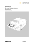
1
Operating Instructions
Sartorius Moisture Analyzer
Model MA35
Electronic Moisture Analyzer
98648-013-57
Intended Use
The MA35 moisture analyzer is
intended for fast and reliable determination of the moisture content
of materials of liquid, pasty and solid
substances using the thermogravimetric method.
●
Symbols
The following symbols are used in
these instructions:
indicates steps you must perform
Contents
2 Intended Use
3 Warnings and Safety Information
Getting Started
General View of the Equipment
Equipment Supplied
Connecting the Moisture Analyzer to
AC Power
11 Leveling the Moisture Analyzer
12 Turning On the Analyzer; Opening and
Closing the Sample Chamber
6
6
7
9
$
indicates steps required only under
certain conditions
13 Operating Design
13 Keys
14 Display
>
describes what happens after you
have performed a particular step
15 Configuration
15 Setting the Device Parameters
17 Setting the Drying Parameters
–
indicates an item in a list
! indicates a hazard
For technical advice on applications:
Phone: +49.(0)551.308.3160
Fax: +49.(0)551.308.3495
21 Operation
21 Example: Analysis with Specified
Drying Time
23
23
23
24
Adjusting the Analyzer
Heating Element Adjustment
Weighing System Adjustment
External Calibration and Adjustment
with a Factory-Defined Weight
26 Interface Port
27 Pin Assignments
28 Error Codes
29 Care and Maintenance
31 Safety Inspection
32
32
33
34
2
Overview
Specifications
Accessories (Options)
Declaration of Conformity
Warnings and Safety Information
This moisture analyzer complies with
the European Council Directives as
well as international regulations and
standards for electrical equipment,
electromagnetic compatibility, and
the stipulated safety requirements.
Improper use or handling, however,
can result in damage and/or injury.
! Make sure before getting started
To prevent damage to the equipment,
read these operating instructions
thoroughly before using your MA35
moisture analyzer. Keep these
instructions in a safe place.
–
Follow the instructions below to
ensure safe and trouble-free operation
of your moisture analyzer:
! Use the moisture analyzer only
for performing moisture analysis
on samples. Any improper use of the
analyzer can endanger persons and
may result in damage to the analyzer
or other material assets.
that the voltage rating printed on the
manufacturer’s label is identical to
your local line voltage (see “Connecting the Moisture Analyzer to AC
Power” in the chapter entitled
“Getting Started”).
–
–
–
–
–
! Do not use this moisture analyzer
in a hazardous area; operate it only
under the ambient conditions
specified in these instructions.
! If you use electrical equipment
in installations and under ambient
conditions subject to stricter safety
standards than those described in the
manual, you must comply with the
provisions as specified in the applicable
regulations for installation in your
country.
–
The moisture analyzer may be
operated only by qualified persons
who are familiar with the properties
of the sample to be analyzed.
–
–
The analyzer comes with a power supply that has a grounding conductor.
The only way to switch the power off
completely is to unplug the power
cord.
Position the power cord so that it
cannot touch any hot areas of the
moisture analyzer.
Use only extension cords that meet
the applicable standards and have a
protective grounding conductor.
Disconnecting the ground conductor
is prohibited.
Connect only Sartorius accessories
and options, as these are optimally
designed for use with your moisture
analyzer.
Note on installation:
The operator shall be responsible for
any modifications to Sartorius equipment or connections of cables not
supplied by Sartorius and must check
and, if necessary, correct these modifications. On request, Sartorius will
provide information on the minimum
operating specifications (in accordance
with the Standards listed on p. 33 for
defined immunity to interference).
Protect the analyzer from contact
with liquid
If there is visible damage to the
equipment or power cord, unplug
the equipment and lock it in a secure
place to ensure that it cannot be used
for the time being.
3
! Clean your moisture analyzer only
according to the cleaning instructions
(see “Care and Maintenance”).
Do not open the analyzer housing.
If the seal is broken, this will result in
forfeiture of all claims under the manufacturer’s warranty.
If you have any problems with your
moisture analyzer:
$
contact your local Sartorius office,
dealer or service center
Warning: Severe Burns!
–
When setting up the moisture analyzer,
leave enough space to prevent heat
from building up and to keep your
analyzer from overheating:
– leave 20 cm (about 8 inches) around
the moisture analyzer
– leave 1 m (3 ft.) above the moisture
analyzer
–
Do not place any flammable substances on, under or near the moisture
analyzer, because the area around the
heating unit will heat up
–
Be careful when removing a sample
from the chamber: the sample, the
heating unit and the sample pan may
still be extremely hot
–
Prevent excess heat build-up around
the analyzer
4
Hazards for persons or equipment
posed by certain sample materials:
Fire
Explosion
– Flammable or explosive substances
– Substances that contain solvents
– Substances that release flammable or
explosive gases or vapors during the
drying process
In some cases, it is possible to operate
the moisture analyzer in an enclosed
nitrogen atmosphere to prevent the
vapor released during drying from
coming into contact with oxygen in the
surrounding atmosphere. Check on a
case-to-case basis whether this method
can be used, because installation of the
analyzer in too small an enclosed space
can affect its functioning (for instance,
through excessive heat build-up within
the analyzer). When in doubt, perform
a risk analysis.
The user shall be liable and responsible
for any damage that arises in connection with this moisture analyzer.
Poisoning
Caustic burns
– Substances containing toxic or caustic
or corrosive components may only be
dried under a fume hood. The value for
the “lower toxic limit” in a work area
must not be exceeded.
Corrosion:
– Corrosion may be caused by substances
that release aggressive vapors during
the heating process (such as acids).
We recommend working with only
small quantities of such samples, to
avoid build-up of vapors that can
condense on cold housing parts and
can cause corrosion.
The user shall be liable and responsible
for any damage that arises in connection with this moisture analyzer.
5
Getting Started
General View of the Equipment
1
9
10
11
12
2
13
2
14
3
15
4
5
6
7
8
Pos.
1
2
3
4
5
6
7
8
6
Designation
Hinged cover with heating element
Leveling feet
On/off key
CF key (clear function; delete)
Enter key (confirm)
‘Down/Back’ key
‘Up/Forward’ key
Print key
Pos.
9
10
11
12
13
14
15
Designation
Disposable sample pan
Pan support
Pan draft shield
Display
Keypad
Interface port
Power jack
The moisture analyzer consists of a
heating unit, a weighing system, and a
display and control unit. In addition to
the socket for AC power (mains supply),
it also has an interface port for connecting peripheral devices, such as a
computer, printer, etc.
Storage and Shipping Conditions
Allowable storage temperature:
0 to 40°C; 32 to 104°F
–
–
–
–
–
–
Do not expose the moisture analyzer
unnecessarily to extreme temperatures,
moisture, shocks, blows or vibration.
Unpacking the Moisture Analyzer
§ After unpacking the equipment, please
check it immediately for any visible
damage
$ If any sign of damage is visible, proceed
as directed under “Safety Inspection” in
the chapter entitled “Care and Maintenance.”
–
–
–
It is a good idea to save the box and all
parts of the packaging until you have
successfully installed your equipment.
Only the original packaging provides the
best protection for shipment. Before
packing your moisture analyzer, unplug
all connected cables to prevent damage.
–
–
–
–
–
Equipment Supplied
The equipment supplied includes the
components listed below:
Moisture analyzer
Power cord
Pan support
Pan draft shield
80 disposable aluminum sample pans
1 pair of forceps
Installation Instructions
The MA35 moisture analyzer is designed
to provide reliable results under normal
ambient conditions in the laboratory
and in industry. When choosing a location to set up your analyzer, observe the
following so that you will be able to
work with added speed and accuracy:
Set up the moisture analyzer on a stable, even surface that is not exposed to
vibrations, and level it using the four
leveling feet
Avoid placing the moisture analyzer in
close proximity to a heater or otherwise
exposing it to heat or direct sunlight
Avoid exposing the moisture analyzer
to extreme temperature fluctuations
Protect the moisture analyzer from
drafts that come from open windows
or doors
Keep the moisture analyzer protected
from dust, whenever possible
Protect the moisture analyzer from
aggressive chemical vapors
Do not expose the equipment to
extreme moisture over long periods
Make sure to choose a place where
excessive heat cannot build up.
Leave enough space between the
moisture analyzer and materials that
are affected by heat.
7
Conditioning the Moisture Analyzer
Moisture in the air can condense on the surfaces
of a cold moisture analyzer whenever it is brought
into a substantially warmer place. If you transfer the
moisture analyzer to a warmer area, condition it for
about 2 hours at room temperature, leaving it
unplugged from AC power. Afterwards, if you keep
the moisture analyzer connected to AC power, the
constant positive difference in temperature between
the inside of the equipment and the outside will
practically rule out the effects of moisture condensation.
Setting up the Moisture Analyzer
§ Position the components listed below in the order
given:
– Pan draft shield
– Pan support
– Disposable sample pan
8
§
$
Connecting the Moisture Analyzer
to AC Power
Check the voltage rating and the plug design
The heating element has been factory-set to 230 V
or 115 volts for technical reasons. The voltage has
been set as specified on your order. The voltage
setting is indicated on the manufacturer’s label
(see the bottom of the analyzer), for example:
– 230 volts: MA35-...230..
– 115 volts: MA35-...115..
! If the voltage indicated on the label does not
–
–
–
§
match your local line voltage:
Do not operate your moisture analyzer; contact
your local Sartorius office or dealer.
Use only
Genuine Sartorius power cords, or
Power cords approved by a certified electrician
If you need to connect an extension cord, use only
a cable with a protective grounding conductor
Connecting the moisture analyzer, rated to Class 1,
to AC power (mains supply):
Plug the power cord into an electrical outlet (mains
supply) that is properly installed with a protective
grounding conductor (protective earth = PE)
Safety Precautions
If you use an electrical outlet that does not have
a protective grounding conductor, make sure to
have an equivalent protective conductor installed
by a certified electrician as specified in the applicable regulations for installation in your country.
Make sure the protective grounding effect is not
neutralized by use of an extension cord that lacks
a protective grounding conductor.
§
Connecting Electronic Peripheral Devices
Make absolutely sure to unplug the analyzer
from AC power before you connect or disconnect
a peripheral device (printer or PC) to or from the
interface port.
9
NOTE: This equipment has been tested
and found to comply with the limits
pursuant to part 15 of FCC Rules.
These limits are designed to provide
reasonable protection against harmful
interference. This equipment generates,
uses and can radiate radio frequency
energy and, if not installed and used in
accordance with these instructions,
may cause harmful interference to radio
communications.
For information on the specific limits
and class of this equipment, please refer
to the Declaration of Conformity.
Depending on the particular class,
you are either required or requested to
correct the interference.
If you have a Class A digital device,
you need to comply with the FCC
statement as follows: “Operation of this
equipment in a residential area is likely
to cause harmful interference in which
case the user will be required to correct
the interference at his own expense.”
If you have a Class B digital device,
please read and follow the FCC
information given below:
“However, there is no guarantee that
interference will not occur in a particular installation. If this equipment does
cause harmful interference to radio or
television reception, which can be
determined by turning the equipment
off and on, the user is encouraged to
try to correct the interference by one or
more of the following measures:
– Reorient or relocate the receiving
antenna.
– Increase the separation between the
equipment and receiver.
– Connect the equipment into an outlet
on a circuit different from that to which
the receiver is connected.
– Consult the dealer or an experienced
radio/TV technician for help.”
Before you operate this equipment,
check which FCC class (Class A or Class
B) it has according to the Declaration of
Conformity included. Be sure to observe
the information of this Declaration
10
Warmup Time
To deliver exact results, the moisture analyzer must
warm up for at least 30 minutes every time you connect it to AC power or after a relatively long power
outage.
Only after this time will the analyzer have reached
the required operating temperature.
Leveling the Moisture Analyzer
Purpose:
– To compensate for unevenness at the place of
installation
– This is particularly important for testing liquid
samples, which must be at a uniform level in the
sample pan
Always level the moisture analyzer again any time
after it has been moved to a different location.
● Extend or retract the front and/or rear leveling feet
as needed to adjust the moisture analyzer
Installing the Aluminum Panels (Optional;
Part No. YDS05MA)
! To prevent burns, allow the glass panels to cool
sufficiently before removing them
! Do not handle the aluminum panels with oily or
greasy fingers
! Do not scratch the aluminum panels; do not use
abrasive or corrosive substances to clean the
aluminum panels
● Remove the 2 rubber caps and the 2 screws beneath
them, and then remove the panel retainer
● Remove the glass panels
● Position the aluminum panels in the retainer
● Fasten the aluminum panels with the retainer and
screws; replace the 2 rubber caps
11
Turning On the Analyzer; Opening and Closing
the Sample Chamber
● To turn on the analyzer: press e
● When opening or closing the sample chamber,
do not release the cover until it is in the fully open
or fully closed position
12
Operating Design
Operation of the moisture analyzer
follows a standardized “philosophy”
which is described below.
There is only one key to a function,
i.e., the key retains this function
throughout most of the menu
levels. The texts and symbols shown
always have the same meaning.
Keys
Some of the keys trigger different functions, depending on whether you press the key
briefly or press and hold the key:
– Press briefly = hold the key down for less than 1.2 seconds
– Press and hold = hold the key down for more than 1.2 seconds
– If you press and hold longer than 1.2 seconds, the function triggered is repeated every
0.6 seconds for as long as you hold the key.
Key
e
c
Designation
On/off key
CF key
u
Enter key
y
Down/Back
key
x
Up/Forward
key
r
Print key
Press briefly
Switch device on or off*
Analysis: cancel function
Menu: cancel selection
Analysis: trigger the
selected function (e.g.,
Menu: store the
selected setting
Analysis: select a
function (e.g., tare)
Menu: decrease value or
return to previous selection
Analysis: select a
function (e.g., tare)
Menu: increase value or
go to next selection
Send readout value
or data record over
the interface port
Press and hold
—
—
Menu: store the
selected setting and
tare) close the menu
Menu: decrease
value 10-fold
Menu: increase
value 10-fold
—
* When you switch off the moisture analyzer, it remains in standby mode
13
Display
The texts and symbols shown on the
display always have the same meaning.
The display is divided into several areas.
Drying parameters/Adjustment function
Graphic
symbols
Result
Function line
Busy symbol,
plus/minus sign,
standby symbol
Unit
Drying parameters:
The following symbols indicate drying program parameters for information, selection
and configuration:
120°C Target temperature
40min Drying time
A
Fully automatic
g
Weight unit or unit
for a calculated value
A
Analysis start
2.0min Interval for automatic
output of intermediate
results
Adjustment function:
b
14
Adjustment function
Busy symbol, plus/minus sign,
standby symbol:
The J symbol is shown here when the
moisture analyzer is processing a function.
The plus/minus sign for the weight value
or calculated value appears here as well,
and the standby symbol when the device
is switched off.
Result:
This section shows the weight or calculated
value.
Unit:
When the weighing system stabilizes, the
unit of measurement for the weight or calculated value is displayed here.
Graphic symbols:
Which symbol is shown here depends
on the operating status of the analyzer.
The examples below indicate “Please close
hood,” “Heating the sample” and “Please
wait” (hourglass).
Function line:
Press the Down/Back or Up/Forward keys
to move the focus and select one of the
functions shown here, and the Enter key to
activate the selected function:
Configuration
Setting the Device Parameters
o Factory setting
√ User-defined setting
Setup
Device
parameters
5. Interface
6. Printing
9. Reset menu
5.1 Baud rate
5.1.3
600 baud
5.1.4 o 1200 baud
5.1.5
2400 baud
5.1.6
4800 baud
5.1.7
9600 baud
5.1.8
19,200 baud
5.2 Parity
5.2.3 o Odd
5.2.4
Even
5.2.5
None
5.3 Number of
stop bits
5.3.1 o 1 stop bit
5.3.2
2 stop bits
5.4 Handshake
mode
5.4.1
Software
5.4.2 o Hardware
5.4.3
None
5.5 Number of
data bits
5.5.1 o 7 bits
5.5.2
8 bits
6.7 Printout
6.7.1
Result only
6.7.2 o Complete (with GLP
and drying
parameters)
6.9 Language
6.9.1
German
6.9.2 o English
6.9.3
US English
(US date/time format)
6.9.4
French
6.9.5
Italian
6.9.6
Spanish
6.9.8
Russian CP1251
6.9.9
Russian CP866
9.1 Factory
9.1.1
settings
Reset to factory settings
9.1.2 o Do not reset
15
Example
Changing the language to US mode (menu item 6.9.3)
Step
Key (or instruction)
1. Select SET in the function line
Repeatedly: x
Display
˚oC
P
min
A
E
min
% MS
g /l
END START
CAL SET PRG
2. Confirm SET
u
5.
3. Select menu item 6
x
6.
4. Open submenu
u
6.7
5. Select menu item 6.9
x
6.9
6. Open submenu
u
6.9.2°
7. Select menu item 6.9.3
y
6.9.3
8. Confirm menu item 6.9.3
u
6.9.3°
9. Close the Setup menu
Repeatedly: c
P
˚oC
min
A
E
TAR
min
% MS
g /l
CAL SET PRG
16
END START
TAR
Setting the Drying Parameters
Select PRG in the function line to adapt parameters for the drying program to the particular
requirements of the product sampled.
Drying Parameters
40 to 160 oC
0.0 min
0.1 to 99 min
Temperature during heating
End of analysis
Select 0.0 minutes for fully automatic shutoff
Select an interval from 0.1 to 99 minutes to define a specific
analysis time
%M
%S
%MS
g
Display mode for result
Moisture
Dry weight
Ratio
Residual weight
E
A
Start of analysis
With stability, after the u key is pressed
Without stability, after the cover is closed
0.0 min
0.1 to 10.0 min
Print intermediate results
Off
17
Features
Temperature during heating
– Adjusted to defined specified temperature during the analysis process
End of Analysis with Shutoff
Parameters
– Fully automatic mode
– Timer mode
Fully automatic mode:
Use the fully automatic mode when
loss of weight on drying follows a clearly
delineated curve which can be unambiguously evaluated (see below).
Start of analysis
– With stability after the u key is
pressed:
When START is shown in the function
line and you press u to confirm,
the initial weight is stored at stability
regardless of whether the cover is open
or closed.
Measurement begins as soon as the
cover is closed.
Weight
Moisture (evaporation)
Automatic shutoff
– Without stability after the cover is
closed:
A symbol shown in the graphic symbol
display prompts you to close the cover
once the initial weight condition is met.
The initial weight is stored without stability as soon as the sample chamber is
closed, and analysis begins.
Time
Timer mode:
The analysis ends as soon as the
specified time has elapsed.
–
–
–
–
Display Mode for Result
The following units can be selected for
displaying analysis results:
Moisture
%M
Dry weight
%S
Ratio
%MS
Residual weight g
Print Intermediate Results
Intermediate results can be printed
either at user-definable intervals or by
pressing the r key.
18
Example: setting the following drying parameters
Final temperature: 130 oC
Start of analysis: without stability after the cover is closed
End of analysis: after 10 minutes
Display mode for result: moisture
Step
Key (or instruction)
Display
1. Turn on the analyzer
e
Self-test runs
l
2. Select PRG: drying program
parameters
y
3. Confirm PRG
(the previously set temperature
is displayed; in this example, 105°C)
u
105°C
4. Set the heating temperature
(in this example: 130°C)
x repeatedly
130°C
5. Confirm heating temperature
u
(the previously set analysis time
is displayed; in this example, 0.0 min)
6. Set the parameter for the
end of analysis; in this example,
10 minutes)
7. Confirm the “end of analysis”
parameter
8. Select the result display mode
(in this example, moisture)
x repeatedly
0.0 min
10 min
u
x or y
%M
19
Step
9. Confirm the display mode
Key (or instruction)
u
Display
E
10. Select the start parameter
(in this example, W/o stability
after the cover is closed)
x or y
A
11. Confirm the start parameter
u
10 min
12. Select setting for printout
of intermediate results (in this
example, no printout = 0.0)
y repeatedly
0.0 min
13. Confirm setting for intermediate
printout of results
u
130°C
14. Save changes and exit menu
for drying parameter input
u > 2 sec
20
Operation
Example: Analysis with Specified Drying Time
The specified drying time in the example is 10 minutes.
Final temperature:
Start of analysis:
End of analysis:
Display mode:
130 oC
Without stability after the cover is closed
After 10 minutes
Moisture
Step
Key (or instruction)
Display
1. Switch on the moisture
analyzer
e
Self-test runs
l
2. Set the drying parameters
(see “Setting the Drying
Parameters” in the chapter
entitled “Configuration”)
3. Open the sample chamber and
place an unused sample pan
on the pan support
4. Tare the sample pan:
select TAR
...and confirm
x or y
as needed
u
P
˚oC
min
END START
CAL SET PRG
5. Distribute approx. 2 g sample
evenly on the sample pan
P
˚oC
min
min
A
E
TAR
min
% MS
g /l
END START
CAL SET PRG
6. Close the sample chamber
A
E
% MS
g /l
P
˚oC
min
A
E
TAR
min
% MS
g /l
CAL SET PRG
END START
TAR
The printout header is
printed: see next page
21
Step
Key (or instruction)
The printout header is
printed
Display
-------------------23.08.2005
11:25
*)
Model MA35-000230V1
Ser. no.
99992581
Ver. no.
00-33-01
ID
-------------------,
Temp.
130 C
Start
W/O STABI.
End
10.0 min
IniWt +
2.036 g
--------------------
*) Date and time included only
if a Sartorius printer model
YDP02 or YDP03 is used
Current moisture loss and elapsed
time are displayed (in this example,
0.36% moisture after 0.3 min)
P
˚oC
A
E
min
min
% MS
g /l
END START
CAL SET PRG
Drying stops automatically
after 10 minutes
P
˚oC
A
E
min
TAR
min
% MS
g /l
CAL SET PRG
The footer of the printout
is printed
END
TAR
-------------------10.0 +
10.90 %M
FinWt +
1.814 g
Name:
--------------------
You can print the result
as often as you wish
by pressing r
Printout when function canceled:
(“B” stands for “Break”)
7. Clear the display
During and after the analysis you
can change the mode for display
and printout of results at any time
by pressing the x and y keys.
22
10.0 +
B 5.7 +
u
10.90 %M
0.03 %M
Adjusting the Analyzer
Heating Element Adjustment
The procedure for adjusting the heating
element is described in the instructions
supplied with the YTM04MA temperature adjustment set.
Weighing System Adjustment
To adjust the weighing system, perform
calibration and adjustment as described
in the following.
Purpose
Calibration is the determination of the
difference between the weight readout
and the true weight (mass) of a sample.
Calibration does not entail making any
changes within the weighing system.
Adjustment is the correction of the
difference between the measured value
displayed and the true weight (mass)
of a sample, or the reduction of the
difference to a level within specified
permissible error limits.
Features
Calibration is performed externally with
the following weight value:
– MA35: 30 g; see “Accessories,” order
no. YSS43
You can have calibration and adjustment results documented as a ISO/GLPcompliant printout (see the page after
next for an example).
External Calibration and Adjustment
with a Factory-Defined Weight
Externally calibrate and adjust the
weighing system using a 30-g
calibration weight.
23
Step
Key (or instruction)
Display
1. Turn on the analyzer
e
Self-test runs
P
˚oC
min
A
E
min
% MS
g /l
END START
CAL SET PRG
2. Select CAL for calibration/
adjustment
x
P
˚oC
min
min
% MS
g /l
END START
CAL SET PRG
3. Confirm CAL
A
E
TAR
u
P
˚oC
min
A
E
TAR
min
% MS
g /l
END START
CAL SET PRG
4. Confirm again when Pb
is shown
u
P
˚oC
min
min
% MS
g /l
END START
CAL SET PRG
5. Tare the weighing system
A
E
TAR
u
P
˚oC
min
A
E
TAR
min
% MS
g /l
END START
CAL SET PRG
6. Select CAL again
x
P
˚oC
min
A
E
TAR
min
% MS
g /l
END START
CAL SET PRG
7. Confirm CAL
u
P
˚oC
min
A
E
TAR
min
% MS
g /l
CAL SET PRG
24
END START
TAR
Step
Key (or instruction)
The prompt for calibration
weight is displayed
Display
˚oC
P
min
A
E
min
% MS
g /l
END START
CAL SET PRG
TAR
8. Open the hinged cover
9. Place the 30-weight on
the weighing system
Minus sign –: weight value too low
Plus sign +: weight value too high
No sign: weight value OK
The weight unit symbol (g) is
displayed at the end of adjustment
˚oC
P
min
A
E
min
% MS
g /l
END START
CAL SET PRG
˚oC
P
min
A
E
TAR
min
% MS
g /l
CAL SET PRG
END START
TAR
Printout after calibration and
adjustment
-------------------23.08.2005
10:51
*) Date and time included only
if a Sartorius printer model
YDP02 or YDP03 is used
Model MA35-000230V1
Ser. no.
99992581
Ver. no.
00-33-01
ID
-------------------External calibration
W-ID
Nom. +
30.000 g
Diff. +
0.001 g
External adjustment
Diff. +
0.000 g
completed
-------------------Name:
*)
--------------------
10. Unload the analyzer
Close the cover
11. Quit calibration/adjustment
c
25
Interface Port
Purpose
The moisture analyzer has an interface
port for connecting an external printer
or computer (or other peripheral device).
External Printer
You can use an external printer to
generate printouts.
Computer
Analyses and calculated values can be
transmitted to a computer for further
evaluation and for documentation.
! Warning When Using Pre-wired
RS-232 Connecting Cables:
RS-232 cables purchased from other
manufacturers often have pin assignments that are incompatible with
Sartorius products. Be sure to check the
pin assignments against the chart on
the next page before connecting the
cable, and disconnect any lines identified differently from those specified by
Sartorius (e.g., pin 11). Failure to do so
may damage or even completely ruin
your moisture analyzer and/or peripheral
device(s).
26
Preparation
For instructions on adapting the interface port to the peripheral device, please
refer to the chapter entitled “Configuration.”
To get the most from the versatile
characteristics of your moisture analyzer
with regard to documentation of
results, we recommend connecting
a printer from Sartorius. The resulting
printouts will contribute decisively
to simplifying GLP-compliant practices.
Female Interface Connector
25-position D-Submini (DB25S) with
screw lock hardware for cable gland
Required Male Connector
25-pin D-Submini (DB25S) with shielded
cable clamp assembly (Amp type 826 985-1C)
and fastening screws (Amp type 164 868-1).
Pin assignments in the 25-contact
RS-232 female connector
Pin 1: Signal ground
Pin 2: Data output (TxD)
Pin 3: Data input (RxD)
Pin 4: Not connected
Pin 5: Clear to send (CTS)
Pin 6: Not connected
Pin 7: Internal ground (GND)
Pin 8: Not connected
Pin 9: Not connected
Pin 10: Not connected
Pin 11: Rechargeable battery: charge voltage
+10 V (1 _out 25 mA)
Pin 12: Reset _Out *)
Pin 13: +5 V output
Pin 14: Internal ground (GND)
Pin 15: Not connected
Pin 16: Not connected
Pin 17: Not connected
Pin 18: Not connected
Pin 19: Not connected
Pin 20: Data terminal ready (DTR)
Pin 21: Not connected
Pin 22: Not connected
Pin 23: Not connected
Pin 24: Not connected
Pin 25: +5 V output
*) = Peripheral device restart
27
Error Codes
Error codes are displayed dynamically, for 2 seconds, or permanently. After a code is displayed
dynamically or for 2 seconds, the program returns automatically to the normal operating mode.
Display
Cause
H
The load exceeds the weighing
L or Err54 Load is below the weighing range
Err 01
Err 02
Err 03
Err 30
Err 31
Err 50
Err 53
Err 55
Err 79
Err 241,
Err 243
Err 2xx
Err 340
Err 342
Data output not compatible with
output format
Calibration/adjustment condition
not met, e.g.,
– not tared
– the pan support is loaded
Calibration/adjustment could not
be completed within a certain time
Interface port for printer output
is blocked
Peripheral device not responding
(interface handshake interrupted;
XOFF, CTS)
Temperature compensation
overflow/underflow
Temperature compensation
not functioning
Output from weighing ADC too high
Dryer adjustment data not found
Weighing system parameters
(EEPROM) defective
Internal error
Operating parameters (EEPROM)
incorrect
Operating parameters (EEPROM)
incorrect except adjustment
parameters
Solution
Unload the pan support capacity
Place the pan support on the weighing
system
Change the configuration in the
Setup menu
Calibrate only when zero is displayed
Select TAR to tare
Unload the moisture analyzer
Allow the scale to warm up
again and repeat the adjustment
Have the port setting changed
by Sartorius Customer Service
Send XON, release CTS
Contact your local Sartorius Service Center
Contact your local Sartorius Service Center
Contact your local Sartorius Service Center
Contact your local Sartorius Service Center
Switch the analyzer off and then
on again. If the error persists, contact
your local Sartorius Service Center
Contact your local Sartorius Service Center
Contact your local Sartorius Service Center
Contact your local Sartorius Service Center
If any other errors occur, contact your local Sartorius Service Center.
Contact information: Please point your Internet browser to: http://www.sartorius.com
28
Care and Maintenance
Service
Regular servicing by a Sartorius
technician will extend the service life of
your analyzer and ensure its continued
accuracy of measurement. Sartorius can
offer you service contracts, with your
choice of regular maintenance intervals
ranging from 1 month to 2 years.
Cleaning
! Make sure that no dust or liquid
enters the moisture analyzer housing
! Do not use any aggressive cleaning
agents (solvents, abrasive cleaning
agents, etc.); clean the moisture
analyzer using a piece of cloth which
has been wet with a mild detergent
(soap) only
The optimum length of the service
interval depends on the operating
conditions at the place of installation
and on your requirements.
●
Repairs
Repair work must be performed by
trained service technicians. Any attempt
by untrained persons to perform repairs
may result in considerable hazards for
the user.
Disconnecting the power supply:
unplug the power cord from the wall
outlet (mains supply); if you have
a cable connected to the interface,
unplug it from the moisture analyzer
$
The pan draft shield and the pan
support can be removed for cleaning
●
Carefully remove any sample
residue/spilled powder using a brush
or a handheld vacuum cleaner
●
After cleaning, wipe down the
analyzer with a soft, dry cloth
29
●
Cleaning the Heating Unit and
Temperature Sensor
Open the hinged cover
! Danger: The terminals of the heating unit are
under live current
30
●
Disconnect the power supply by unplugging the
power cord from the wall outlet (mains)
If you have a cable connected to the interface
port, disconnect it from the moisture analyzer
●
Carefully remove any residue from the
temperature sensor
●
Use a brush or a damp, lint-free cloth to clean
the tubular metal heating element.
Safety Inspection
If there is any indication that safe
operation of the equipment is no longer
warranted:
● Disconnect the power supply by
unplugging the power cord from the
wall outlet (mains)
> Lock the equipment in a secure place
to ensure that it cannot be used for the
time being
Safe operation of the equipment is no
longer ensured when:
– there is visible damage to the device
or power cord,
– the analyzer no longer functions properly,
- the equipment has been stored for a
relatively long period under unfavorable
conditions, or
– the equipment has been subjected to
rough handling during shipment.
In this case, notify your nearest
Sartorius Service Center. Maintenance
and repair work may be performed only
by service technicians who are authorized by Sartorius and who:
– have access to the required service and
maintenance manuals, and
– have attended the relevant service
training courses.
We recommend having the moisture
analyzer inspected regularly according
to the following checklist by a qualified
Sartorius service technician:
– Resistance of the protective grounding
conductor < 0.2 ohm measured with
a commercially available multimeter
– Insulation resistance > 2 megaohms
measured with a constant voltage of at
least 500 volts at a 500 kohm load
A qualified Sartorius service technician
should determine which tests are
performed at what intervals, based
on ambient and operating conditions.
Inspections must be performed at least
once a year.
Recycling
If you no longer need the
packaging after successful
installation of the equipment, you should return it
for recycling. The packaging
is made from environmentally
friendly materials and is a valuable
source of secondary raw material.
Batteries are hazardous waste and must
be disposed of separately. Please deposit
empty batteries in the collection boxes
set up in your area for this purpose.
On request, Sartorius can provide GRS
boxes for collecting used batteries (GRS
stands for “Gemeinsames Rücknahme
System,” a German organization for
battery disposal). Contact your local
waste disposal authorities if you wish to
scrap the equipment. Remove batteries
before scrapping the equipment.
Sartorius AG in Goettingen will take
back equipment and packaging for
disposal in accordance with the
applicable laws.*
* This service is offered only within
Germany. If you set up the equipment
in a country other than Germany,
please contact your local waste disposal
authorities for information on similar
services.
31
Overview
Specifications
Weighing capacity (Max)
Accuracy of the weighing system
Repeatability (average)
35 g
1 mg
from about 1 g initial sample: ± 0.2 %
from about 5 g initial sample: ± 0.05 %
Readability
0.01 %
Display of results
% moisture
% dry weight
% ratio
g residual weight
Shutoff criteria
Fully automatic
Timer mode: 0.1 to 99 min
Sample heating
Infrared radiation from a tubular metal heating element
Access to sample chamber
Flip-open cover with wide-angle opening
For conformity with FDA/HACCP regulations Aluminum panels (in place of glass panels)
Operating temperature range and setting
40°C to 160°C (104°F to 320°F), adjustable in 1°C increments
Operator guidance
Symbols
Program memory capacity
1 program
Measured value memory capacity
Final value stored until subsequent measurement begins
Printout of measured values
Short printout
GLP-compliant record in German, English, French, Italian,
Spanish or Russian
Interface port
RS-232C, 25-pin connector for transfer of values to a
printer or computer
Housing dimensions in mm
Width 224, depth 366, height 191
Net weight, approx.
5.8 kg
Power requirements (supply voltage):
230 V or 115 V (depending on the model) (–15% … +10%);
50 – 60 Hz
Frequency
48 – 60 Hz
Fuses
2 (zero conductor/phase), 6.3 A, time-lag (slow-blow),
5 + 20 mm (internal)
Power consumption
400 VA
Ambient conditions:
Operating temperature range:
+10 ... +30°C (+50° ... +86°F)
Allowable ambient operating temperature: +5°C .... +40°C (+41°F ... +104 °F)
Ambient storage temperature:
–20°C ... +70°C (-4°F ... +158°F)
Relative humidity:
Up to 80% at +31°C (+ 88°F) ambient temperature; linearly
decreasing down to 50% at +40°C (+104°F), non-condensing
Operating altitude
For use above sea level up to 2,000 m (6,562 feet);
indoor use only
32
Accessories (Options)
Accessories
80 disposal sample pans
Aluminum; 90 mm d
80 glass fiber filters
For liquid and pasty samples and
samples with high fat-content
Exchangeable panels for flip-open cover
Replaces glass with aluminum panels
for compliance with FDA/HACCP regulations
(upgrade kit)
Model YDP03-0CE data printer for
external connection
Color ink ribbon for YDP03-0CE data printer
Paper for YDP03-0CE data
printer; 5 rolls; length: 50 m
External calibration weight 30 g ± 0.3 mg
Temperature adjustment set
Standard Operating Procedure (SOP)
Order No.
6965542
6906940
YDS05MA
YDP03-0CE
6906918
6906937
YSS43
YTM04MA
(available starting 2006)
YSL02MA
33
Declarations of Conformity
C
34
Sartorius AG
Weender Landstrasse 94–108
37075 Goettingen, Germany
Phone +49.551.308.0
Fax +49.551.308.3289
www.sartorius.com
Copyright by Sartorius AG,
Goettingen, Germany.
All rights reserved. No part
of this publication may
be reprinted or translated in
any form or by any means
without the prior written
permission of Sartorius AG.
The status of the information,
specifications and illustrations
in this manual is indicated
by the date given below.
Sartorius AG reserves the
right to make changes to the
technology, features,
specifications and design of the
equipment without notice.
Status:
November 2005, Sartorius AG,
Goettingen, Germany
Printed in Germany on paper that has
been bleached without any use of chlorine
W1A000 · KT
Publication No.: WMA6032-e05112