1
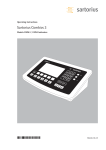
Operating Instructions
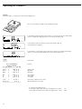
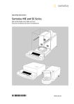
Sartorius Combics 1| Combics 1 plus | Combics 2
Models CISL1 | CISL1N | CISL2 | CIS1 | CIS1N | CIS2
Indicators
98648-010-85
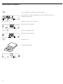
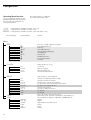
Intended Use
Combics 1, Combics 1 plus and
Combics 2 are rugged display and
control units for the complex quality
control tasks you perform every day.
They meet the highest requirements
placed on the accuracy and reliability
of weighing results:
–
–
–
–
in the food industry
in the pharmaceutical industry
in the chemical industry
in the electronics and metal-working
industries
Combics indicators are:
– Rugged and durable
(stainless steel housing)
– Easy to clean and disinfect
– Easy to operate, thanks to the following
features:
– large, backlit display segments
– large keys with positive click action
– Independent of the weighing
instrument location
– Equipped with a range of interfaces
for flexible use
– Password-protected from unauthorized
changes in parameters (optional)
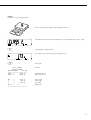
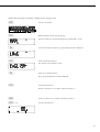
Combics 1 plus speeds up your routine
procedures with:
– Input functions for tare values
through numeric keypad
– Option for 2 alphanumeric lines
to identify samples
– Connectivity for bar code scanner
to enter tare values or ID codes
2
Combics 2 indicators have the following
features:
– Built-in application programs:
– Counting
– Neutral measurement
– Weighing in percent
– Averaging
– Checkweighing
– Classification
– Net-total formulation
– Totalizing
– Automatic initialization when you
switch on the Combics
– Automatic taring when a load is placed
on the weighing instrument
– Optional remote control using an
external computer
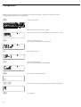
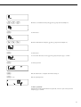
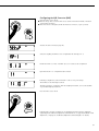
Symbols
The following symbols are used in
these instructions:
§ indicates required steps
$ describes what happens after you
have performed a certain step
! indicates a hazard
Hotline:
For advice on the use of these
applictions, just call or fax your local
Sartorius office. For the address, please
visit our Internet website at:
www.sartorius.com
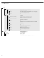
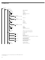
Contents
2
Intended Purpose
3
Contents
4
Warnings and Safety Precautions
5
Getting Started
6
General View of the Equipment
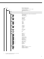
7
7
9
Operating Design
Weighing/Measurement
Configuration (Operating Menu)
10
10
18
20
22
26
30
35
40
44
47
50
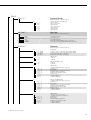
Operation
Weighing W
Individual ID Codes
Calibration and Adjustment
Counting Z
Neutral Measurement Z nm
Checkweighing O
Classification O cl
Weighing in Percent %
Averaging (Animal Weighing) V
Net-total Formulation R
Totalizing Σ
54
54
55
56
58
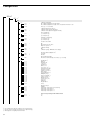
Configuration
Operating Menu Overview
Setting the Language (Example)
Entering/Changing the Password (Example)
Operating Menu Overview (Parameters)
74
74
76
78
82
83
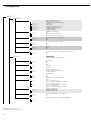
Service
Connecting a Weighing Instrument
Service Menu
Configuring the Analog/Digital Converter
Geographical Data
Entering Calibration and
Linearization Weights
Function of the ) Key (> 2 sec)
External Linearization
Set Preload
Clear Preload
Calibration/Adjustment without Weights
84
85
86
87
88
Data Interfaces
Pin Assignment Charts
Installing the Interface Cable
Cabling Diagram
Connecting the External Rechargeable
Battery Pack
95 Connecting a Bar Code Scanner
95 Synchronization
96 Configuring the Data Interface
as a COM Port
96 Data Input Format
97 Data Output Format
99 Configuring the Data Interface
as a Printer Port
100 Configuring Printouts
101 Sample Printouts
89
91
93
94
95
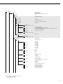
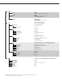
104 Error Codes
105
105
105
105
Care and Maintenance
Repairs
Cleaning
Safety Inspection
106 Recycling
107
107
108
109
112
114
116
118
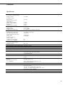
Overview
Specifications
Dimensions (Scale Drawings)
Accessories
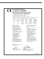
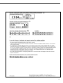
Declaration of Conformity
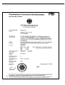
EC Type-approval Certificate
Plates and Markings
Index
Appendix
General Password
Guide to Verification (on CD-ROM)
3
Warnings and Safety Precautions
Safety Information:
§ Please read these operating instructions
carefully before using your indicator
to prevent damage to the equipment.
! Do not use this equipment in
hazardous areas.
! Use only standard cables that have
protective grounding conductors.
The protective conductor must not
be disconnected for any reason.
! Disconnect the indicator from power
before connecting or disconnecting
peripheral devices.
! The indicator may be opened only
by trained service technicians.
! If you operate the equipment under
ambient conditions subject to higher
safety standards, you must comply with
the applicable installation regulations.
! If there is visible damage to the
equipment or power cord, unplug the
equipment and make sure it cannot
be used for the time being.
Installation:
– Proceed with extreme caution when
using pre-wired RS-232 connecting
cables from other manufacturers,
as the pin assignments may not be
compatible with Sartorius equipment.
Check all pin assignments against the
cabling diagrams and disconnect any
lines that are not assigned.
– Connect only Sartorius accessories and
options, as these are optimally designed
for use with your Combics indicator.
The operator shall be solely responsible
for installation and testing of any
modifications to Sartorius equipment,
including connection of cables or
equipment not supplied by Sartorius.
Contact Sartorius for detailed operating
specifications in accordance with the
Standards for immunity to interference.
$ If you have any problems with your
Combics indicator, contact your local
Sartorius customer service center.
IP Rating:
– CISL models are rated to IP44
(with Option L1: IP65); CIS models are
rated to IP67.
– The IP65/IP67 protection rating is
ensured only if the rubber gasket is
installed and all connections are
fastened securely (including the caps on
unused sockets). Weighing instruments
must be installed and tested by a
certified technician.
– If you install an interface port after
setting up your indicator, keep the
protective cap in a safe place for future
use. The cap protects the interface
connector from vapors, moisture and
dust or dirt.
Using the Equipment in Legal
Metrology in the EU*:
– When the indicator is connected to a
weighing instrument and the resulting
weighing instrument is to be verified,
make sure to observe the applicable
regulations regarding verification. When
connecting a Sartorius weighing instrument, please observe the “Guide to
Verification" on the enclosed CD and
the permitted weighing range as listed
in the Declaration of Conformity.
– EU legislation requires that a control
seal be affixed to the verified device.
The control seal consists of a sticker
with the “Sartorius" logo. This seal will
be irreparably damaged if you attempt
to remove it. If any of the verification
seals are damaged, make sure to observe
the national regulations and standards
applicable in your country in such cases.
In some countries, the verification will
become null and void and the equipment must be re-verified.
* Including the Signatories of the Agreement on the European Economic Area
4
Getting Started
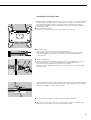
Unpacking the Indicator
§ Unpack the equipment and check it
immediately for any visible damage.
$ If you detect any damage, proceed
as directed in the chapter entitled
“Care and Maintenance," under “Safety
Inspection."
$ Save the box and all parts of the packaging for any future transport. Unplug
all connected cables before packing the
equipment.
Equipment Supplied
– Indicator
– Operating instructions (this manual)
– Special accessories listed on the bill
of delivery, if ordered
Installation Instructions
Choose a location that is not subject to
the following unfavorable conditions:
– Excessive temperatures (operating
temperature range: -10°C to +40°C;
+14°F to +104°F)
– Aggressive chemical vapors
– Excessive moisture (depends on
IP rating)
Conditioning the Indicator
Moisture in the air can condense on
cold surfaces whenever the equipment
is moved to a substantially warmer
place. To avoid the effects of condensation, condition the indicator for about
2 hours at room temperature, leaving it
unplugged from AC power.
Installation Steps
Connecting the Indicator to AC Power
§ Check the voltage rating and the plug
design. The indicator has a built-in
power supply which can be operated
with a supply voltage of 100 V to 240 V.
The power connection must be made
in accordance with the regulations applicable in your country.
! To power a device of protection class 1,
make sure the electrical outlet (mains
supply) is properly installed with a protective grounding conductor (protective
earth, PE).
! If the electrical outlet does not have
a protective grounding conductor, have
a certified electrician install equivalent
protection. The protective conductor
must not be disconnected at any time.
! Make absolutely sure to unplug the
indicator from AC power before you
connect or disconnect a peripheral
device (printer or PC).
$ Switch off the equipment when not
in use.
Note:
This equipment has been tested and
found to comply with the limits pursuant
to part 15 of FCC Rules. These limits are
designed to provide reasonable protection against harmful interference. This
equipment generates, uses and can radiate radio frequency energy and, if not
installed and used in accordance with
these instructions, may cause harmful
interference to radio communications.
For information on the specific limits
and class of this equipment, please refer
to the Declaration of Conformity.
Depending on the particular class, you
are either required or requested to correct
the interference.
–
–
–
–
If you have a Class A digital device, you
need to comply with the FCC statement
as follows: “Operation of this equipment
in a residential area is likely to cause
harmful interference in which case the
user will be required to correct the interference at his own expense."
If you have a Class B digital device,
please read and follow the FCC information given below:
“[…]However, there is no guarantee that
interference will not occur in a particular
installation. If this equipment does cause
harmful interference to radio or television
reception, which can be determined
by turning the equipment off and on,
the user is encouraged to try to correct
the interference by one or more of the
following measures:
Reorient or relocate the receiving antenna.
Increase the separation between the
equipment and receiver.
Connect the equipment into an outlet
on a circuit different from that to
which the receiver is connected.
Consult the dealer or an experienced
radio/TV technician for help."
Before you operate this equipment,
check which FCC class (Class A or Class
B) it has according to the Declaration of
Conformity included. Be sure to observe
the information of this Declaration.
Warmup Time
To ensure accurate results, the indicator
must warm up for 30 minutes before
operation. Only after this time will the
indicator have reached the required
operating temperature.
If the equipment is used in legal metrology, make sure to allow at least 24 hours
warmup time after initial connection to
AC power or after a relatively long power
outage.
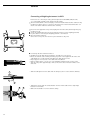
1) Connect the weighing instrument to
the indicator: see page 74
2) Configure the A/D converter:
see page 78
3) Perform calibration/adjustment:
see page 20; see also page 85 for
linearization
4) Connect peripheral devices
(e.g., printer ) to COM1 or UniCOM:
see the chapter entitled “Data
Interfaces," starting on page 89
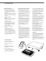
5
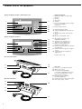
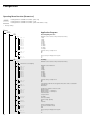
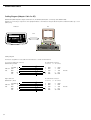
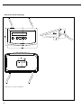
General View of the Equipment
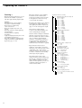
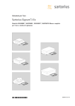
Display and keypad: Combics 1 and Combics 1 plus
1
7*
2
3
8*
4
9*
5
10*
6
10*
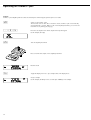
Display and Keypad:
1 Display (for details, see “Operating
Design")
2 Zero key
3 On/off key
4 Tare key
5 Function key (toggle gross/net, weight
unit or to 10 + higher
resolution)
6 Print key (data output)
7* Numeric keypad for input
8* “Clear” key (deletes ID codes and tare
input)
9* “Info" key (shows ID codes and tare
input)
10* ID key (for entering ID codes)
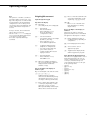
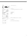
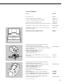
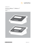
Display and keypad: Combics 2
12
13
1
2
14
15
3
16
11
6
5
4
11 WP toggle key (toggles active
weighing instrument)
12 “Clear function” key (function
depends on active application)
13 LEDs (for Checkweighing and
Classification applications)
14 Reference value key (function depends
on application)
15 “OK" key (function depends on application)
16 Toggle key (function depends on
application)
* Combics 1 plus only
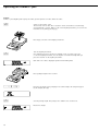
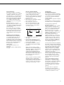
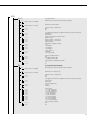
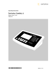
Rear view: CISL models
17
19
18
20
21
Rear view: CIS models
19
22
20
17
18
21
6
Rear view:
17 Connector for weighing instrument
18 Menu access switch
19 Second interface (“UniCOM")
for external rechargeable battery and
bar code scanner (Combics 2 only) –
Other functions optional
20 RS-232C interface (“COM1")
(standard equipment)
21 Power cord with country-specific plug
22 Vent valve; torque: 1.5 Nm
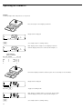
Operating Design
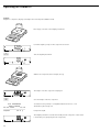
Keys
The operation of Combics 1, Combics 1
plus and Combics 2 involves just a few
keys. These keys have one function during measurement and another during
configuration. Some of the keys have
one function when pressed briefly, and
another when held for longer than 2
seconds.
If a key is inactive, this is indicated as
follows when it is pressed:
– The error code “-------" is displayed
for 2 seconds. The display then returns
to the previous screen content.
– An acoustic signal (double-beep)
is emitted.
I Press to enter data (either ID code
or tare value, depending on subsequent key; e.g., ) for tare)
Weighing/Measurement
Input Through the Keypad
g, h
Press to store or view ID codes
(user-defined data to identify
weight values)
Keys below the Display
e On/off key
(in standby mode, off is displayed).
( – Press briefly:
Zero the instrument
– Press and hold (> 2 sec ):
Show the adjustment/
configuration counter
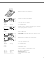
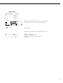
Keys to the Right of the Display on
Combics 2
These keys are used for operating
applications. Please refer to the individual application descriptions for details.
) – Tare the instrument
– Save numeric input as tare weight
(Combics 1 plus only)
– Press and hold (> 2 sec ):
Start calibration/adjustment
k
c Deletes initialization values or
totalizing memory, depending on
configuration.
r For modifying reference values.
Toggle the display between
(depends on configuration):
– first and second weight unit,
– gross and net values, or
– normal and 10-fold increased
display resolution
O Store a value or start an
application program.
w Toggle between display modes
within an application program
p – Press briefly: Print
– Press and hold (> 2 sec ):
Print GMP footer
n When two weighing instruments
are connected, this key toggles the
display between instruments
(Combics 2 only).
Keys to the Right of the Display on
Combics 1 plus
Keys for entering ID codes and tare values
1, 2, 3… 9, .
Numeric keypad for entering
values that are identified by the key
subsequently pressed (e.g., ) for
tare input or “ID" key for ID codes)
–
–
–
–
–
–
–
Input Through the Digital Input Port
The indicator is equipped with a control
input (universal input port). You can
connect a hand switch or foot switch
to this port, if desired. Assign one
of the following functions to this port
in the operating menu:
p key
p (> 2 sec.)
) key
) key (> 2 sec.)
k key
n key
O key
E Press to delete data (either ID code
or tare input, depending on subsequent key; e.g., ) for tare)
When pressed during numeric input:
deletes the last character entered
7
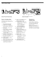
Operating Design
123
123
4
4
15
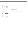
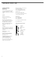
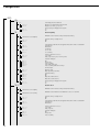
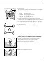
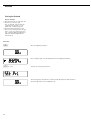
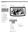
Display during weighing/measurement
(Combics 1, Combics 1 plus) (example)
14
The illustration above shows all of the
main display elements and symbols shown
during weighing.
15
2
3
4
5
6
7
8
9
10
11
12
13
8
9 10 11 14 12
17
18 17 19 13
Busy symbol; indicates that an
internal process is in progress
± sign for the value displayed
Identifies “zero" as a weight value
(after the weighing instrument has
been zeroed)
Weight value or calculated value
(main display)
In legal metrology, on equipment
with e = d, the digit shown with
a border is not valid
Identification of calculated value
in the main display (value not valid
in legal metrology)
Weight unit of the value displayed
Net value in the main display
(when data is stored in tare memory)
Gross value in main display
(when data is stored in tare memory)
Printing in progress
Display of the range on multiplerange instruments
GMP-compliant printing in progress
(Combics 1 plus and Combics 2 only)
Battery symbol showing status of
rechargeable battery (empty outline
indicates battery is drained)
16
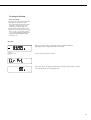
Display during weighing/measurement
(Combics 2) (example)
Display in Weighing Mode
1
5 6 7 8
5 6 7 8 9 10 11 12 13
16
17
18
19
Indicates active weighing instrument;
flashes to prompt calibration/
adjustment (Combics 2 only)
Bar graph (Combics 2 only)
– Shows how much of the available
weighing capacity is “used up" by
the current load, or
– Shows the measured value in
relation to a target value
(with the Checkweighing or
Classification application)
Symbols for Checkweighing and
classification (Combics 2 only)
Application symbols:
Totalizing, Checkweighing,
Classification, Net-total Formulation,
Weighing in Percent, Counting and
Neutral Measurement.
For details, please refer to the the
descriptions of the applications
(Combics 2 only).
Symbols for reference updating
(Combics 2 only)
– Auto: Depending on the weight
value, a reaction is triggered in
the application
– Opt: Automatic reference
updating has been performed
(Counting application)
Numeric display; e.g., shows
reference value (Combics 2 only)
Saving Data in
Weighing Mode
All of the application parameters
saved (e.g., reference values) remain
stored and are still available when
– you switch the Combics off and
then back on again
– you return to the originally selected
application from a second one
(for example, when you switch from
Averaging back to Counting, all parameters saved for Counting are available)
1
2 3
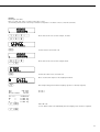
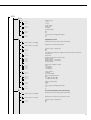
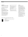
Display of menu settings: Text menu (example)
Configuration
(Operating Menu)
4
5
Navigating the Menu
( Close the active submenu and return
to next higher menu level (“back")
) – Press briefly (< 2 sec):
Select and store a menu item
– Press and hold (> 2 sec ):
Exit the menu
k Show the next item on the
same menu level (the display scrolls
through all items in series)
p Print the menu settings starting
from the current position, or print
Info data
3
4
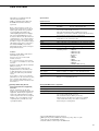
Display of menu settings: Numeric menu (example)
Alphanumeric Input in the Menu
Navigation and input in the operating
menu are implemented using the keys
below the display (on Combics 1 plus,
numeric values can be entered using
the numeric keypad)
Opening the Menu
Press the e key to switch the Combics
off and then on again; while all segments
are displayed, press the ) key briefly.
7
6
Numeric input in Combics 1 plus
operating menu:
Enter values (date and time, etc.) using
the 10-key numeric keypad
Display of Menu Settings
The illustration above shows all of the
main display elements and symbols shown
during menu configuration.
1
( – Press briefly:
Activate character to the left of
the current character (when first
character is active: exit input
mode without saving changes)
– Press and hold (> 2 sec ):
Exit the input mode without
saving changes
) – Press briefly (< 2 sec):
Confirm currently active character
and move 1 position to the right
(after the last character: store
input)
– Press and hold (> 2 sec ):
Store current input and display
the menu item
k – Cursor in first position, no characters entered yet: Delete character(s) and enter 0
– Change the displayed character;
scroll forward (sequence: 0 to 9,
decimal point, minus sign, Z to A,
space)
2
3
4
5
6
7
Selected menu item on text level
(e.g., “Printer" for configuring the
connected printer)
Indication that there are additional
submenus
Indication that this is the currently
active setting
Menu history (indicates the highest
menu level)
Highest level in numeric menu
Second level in numeric menu
Third level in numeric menu
Saving Data in Configuration Mode
The parameters selected in the operating
menu remain stored after you switch off
the Combics.
You can prevent unauthorized changes
in operating menu settings by requiring
password input for menu access.
p – Cursor in first position, no characters entered yet: Delete entire
string and enter a space
– Change the displayed character;
scroll backwards (sequence:
Space, A to Z, minus sign,
decimal point, 9 to 0)
9
Operation
Weighing W
The basic weighing function is available
at all times.
Features:
– Zero the weighing instrument
by pressing (
– Store the weight on the instrument
as tare by pressing )
– Tare container weight automatically
– Enter tare weight through bar code
scanner (Combics 1 plus and
Combics 2 only)
– Enter tare weight through numeric
keypad (Combics 1 plus only)
– Delete tare values by pressing 0
and ) or E and ) (Combics 1
plus only)
– Press k to toggle the display
between:
– Gross and net values,
– 1st and 2nd weight unit, or
– normal and 10-fold higher resolution
– Weighing with two weighing instruments (Combics 2 only)
– Individual data ID codes with numeric
values for identifying weight values
(Combics 1 plus only)
– Print weight value:
– GMP-compliant printout
– Automatic printing
– Automatic data output
(see “Data Interfaces")
10
Automatic Taring (Menu Item 3.7)
When menu item 3.7.2 is active,
the first load placed on the weighing
instrument that exceeds the specified
minimum load is stored, at stability,
in the tare memory.
The weighing instrument returns to
the initial state when the load is less
than 50% of the minimum load.
Minimum Load for Automatic
Taring and Automatic Printing
(Menu Item 3.5)
You can choose from the following
settings for the minimum load:
1 digit (no minimum load)
2 digits
5 digits
10 digits
20 digits
50 digits
100 digits
200 digits
500 digits
1000 digits
The “digits" here refer to the intervals
in the connected weighing instrument.
If the interval of the connected instrument is 1 g, for example, and 1000 digits
are required, the minimum load is
1000 g (=1000 digits).
If the interval of the connected instrument is 5 g and the same number of
intervals is required as in the example
above, the minimum load is 5000 g.
Once the load on the weighing
instrument exceeds the specified minimum, the instrument is tared and/or a
printout is generated, if the operating
menu is configured for automatic taring
(menu item 3.7.2) and/or automatic
printing (menu item 7.13.2).
Automatic Printing (Menu Item 7.13)
When menu item 7.13.2 is active,
the first weight value that exceeds the
specified minimum load is printed.
If the menu code for automatic taring
is also active, the weighing instrument
is only tared when the minimum load
is exceeded; the value is not printed.
First Weighing Instrument Displayed
(Combics 2 only)
You can define which weighing instrument shows the first weight value when
you switch on the Combics, under
utilit (menu item 8.9).
Entering Tare Weight using
a Bar Code Scanner (Combics 1 plus
and Combics 2 only)
You can enter the tare value of a
container using a bar code scanner.
To do this, the “Store value as tare"
(tare) menu item must be selected
under “Setup > Bar code" in the
operating menu. In this case, the value
is stored as the tare automatically, without pressing the t key. The contents
of the tare memory are display in Info
mode (press and hold w).
Entering ID Codes using a Bar Code
Scanner (Combics 1 plus only)
You can use a bar code scanner to
enter ID codes.
To do this, the “Store value as ID1"
(id1) menu item must be selected
under “Setup > Bar code" in the
operating menu. In this case, the value
is stored as ID1 automatically, without
pressing the g key.
To store the second ID code, the h
key must be pressed.
To view the stored ID codes:
– Press I and g
– Press I and h
Calibration/Configuration
Counter on Standard
Weighing Instruments
Purpose
These two mutually independent
counters automatically keep track of
changes made in calibration/adjustment
parameters and in the operating menu.
Counter values are stored in an EEPROM, and remain stored during the
entire service life of this memory chip.
To view the current values in the
counter, press and hold the ( key
(longer than 2 sec). The readout shows
the “configuration counter" value for
3 seconds first (identified by “P").
Then the “calibration counter" value is
shown for 3 seconds (identified by “C").
The information display closes automatically after 6 seconds.
Features of the Calibration Counter:
– Limited to a count of 9999
– Counter set to “C 0000" when the
hardware is first put into operation
– Counter cannot be reset
– The counter value is updated (“1” is
added) automatically following:
– Successful calibration/adjustment
or linearization
– Changes in the user-defined calibration/adjustment or linearization
weight (menu item 1.18)
– Changes in any of the following
parameters:
Function of the q key (menu item
1.9)
Zero-setting range (menu item 1.11)
Initial zero-setting range (menu item
1.12)
Resetting of the above parameters
to factory settings (menu item 9.1.1)
–
–
–
–
Features of the Configuration
Counter:
Limited to a count of 9999
Counter set to “P 0000" when the
hardware is first put into operation
Counter cannot be reset
The counter value is updated
(“1" is added) automatically following:
– Changes in the following
parameters:
Place of installation (menu item 1.1)
Application filter (menu item 1.2)
Stability range (menu item 1.3)
Taring (menu item 1.5)
Auto zero (menu item 1.6)
Weight unit 1 (menu item 1.7)
Weight unit 2 (menu item 3.1)
Weight unit 3 (menu item 3.3)
Resetting of the above parameters to
factory settings (menu item 9.1.1)
– Function of the k key changed
to or from 10-fold higher resolution
display
– Activation or deactivation of application-dependent automatic taring
(menu item 3.7)
– Resetting of the application parameters to factory settings (menu code
9.1.1)
Device parameters
Password
You can prevent unauthorized changes
in the device settings (“Setup") and
application settings (“Appl," Combics 2
only) by assigning a password under
“Setup > Code" (Code; see also the
chapter entitled “Configuration").
Acoustic Signal
An acoustic signal is emitted when
you press a key (active key: single beep;
inactive key: double-beep).
You can switch the acoustic signal off
or on under “Setup > Utilities" (Setup,
Utilit) (menu item 8.2).
Keys
In the Setup menu under “Utilit,"
you can block or release the keypad for
input (menu item 8.3).
Automatic Power-off
In the Setup menu under “Utilit"
you can configure the Combics to
shut down automatically following
a specified interval of no user activity
(menu item 8.7).
Display Backlighting
In the Setup menu under “Utilit"
you can choose from the following
settings for the display backlighting:
– On (8.8.1)
– Off (8.8.2)
– Shut off after the specified time
period has elapsed (8.8.3)
Timer Mode
In the Setup menu under “Utilit"
you can set the timer interval to
2, 4 or 10 minutes (menu item 8.9).
11
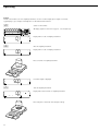
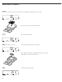
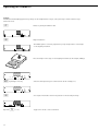
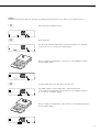
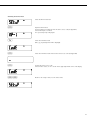
Operating
Example
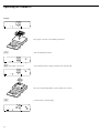
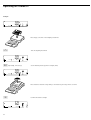
Switch on the Combics, zero the weighing instrument, tare the container weight, place sample in container,
toggle display to gross weight, 2nd weight unit or 10-fold increased resolution
e
Switch on the Combics
8888888
01
8
All display segments are shown for approx. 1 second (self-test)
188
8
Display with no load on weighing instrument
188
(
Zero the weighing instrument
00
8
Display with no load on weighing instrument
188
Place container on weighing instrument
Comb
ics 2
-
n
CF
0
T
RE
F
Fn
OK
500
8
Container weight is displayed
188
)
Tare the weighing instrument
00
8
Display with tared container on weighing instrument
188
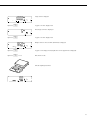
Place sample in container (in this example, 120.2 g)
Comb
ics 2
-
n
CF
0
T
RE
F
Fn
12
OK
1202
8
Display with tared weighing instrument and sample in container
188
k
Toggle display; readout depends on your settings:
1702
8
gross weight
(in this example, 50 g for container + 120.2 g substrate) or
188
display in 2nd weight unit (in this example, kg) or
12023
8
display with 10-fold increased resolution
188
k
Return to previous readout
(if 10-fold increased resolution is shown, display returns to previous readout
automatically after 10 seconds)
1202
8
188
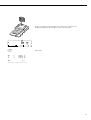
p
Print results
ACE HARDWARE
GOETTINGEN
24.02.2002
15:10
-------------------G#
+
170.2 g
T
+
50.0 g
N
+
120.2 g
--------------------
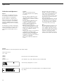
13
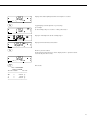
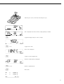
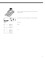
Operating the Combics 1 plus
Example:
Combics 1 plus: Weighing with tare value entered using the numeric keypad; generate printout of results
e
.25
)
Switch on the Combics 1 plus
The automatic self-test runs. Once a readout is shown, Combics 1 plus is automatically
zeroed and ready to operate. With no load on the weighing instrument, you can zero the
instrument at any time by pressing (.
Enter the tare weight in the current weight unit using the keypad
(in this example, 0.25 kg).
Tare the weighing instrument
Place container with sample on the weighing instrument
Read the result
k
Toggle the display from net to gross weight values. The display shows
the gross weight
(in this example, 0.250 kg for the container plus 2.000 kg for the sample)
14
k
Toggle to display of net value
p
Print the results
-------------------05.04.2004
10:09
Model
CIS1N
Ser.no.
12345678
Vers.
1.0001.04.4
BVers.
01-33-01
-------------------ACE HARDWARE
GOETTINGEN
Batch no.
123456
Customer
6.789
05.04.2004
10:09
-------------------G#
+
2.250 kg
T
+
0.000 kg
PT2
+
0.250 kg
N
+
2.000 kg
--------------------------------------05.04.2004
10:10
Name:
Start of GMP header (only if GMP-compliant printout is configured)
End of GMP header
Header lines
ID code 1
ID code 2
GMP footer (only if GMP-compliant printout is configured)
--------------------
End of GMP footer
E+)
Delete tare weight entered through the keypad
or
0+)
15
Operating the Combics 1 plus
Example:
Combics 1 plus: Weighing with varying tare values; generate printout of results, delete tare values
e
Switch on the Combics 1 plus
The automatic self-test runs. Once a readout is shown, the Combics is automatically
zeroed and ready to operate. With no load on the weighing instrument, you can zero the
instrument at any time by pressing (.
Place empty container on the weighing instrument
)
Tare the weighing instrument
Note: With the automatic tare function enabled, you do not need to press )
to tare the weighing instrument; the tare weight is stored automatically when you
place the container on the weighing instrument.
Wait until a zero value is displayed together with the NET symbol.
Place packaged sample in the container
.25
)
Enter the tare weight of the packaging in the current weight unit using the keypad
(in this example, 0.25 kg).
Save the package weight. The package tare is added to the container tare.
Read off net weight
16
p
Print the results
G#
+
6.433 kg
T
+
4.183 kg
PT2
+
0.250 kg
N
+
2.000 kg
--------------------
0
Enter a zero (“0") using the keypad
)
Save the value entered. This deletes tare values; the display shows the gross value
p
Print the results
G#
+
6.433 kg
T
+
0.000 kg
N
+
6.433 kg
--------------------
17
Operating the Combics 1 plus
Individual ID Codes
(Identifiers)
You can assign ID codes (such as product name, batch number, etc.) while
weighing, for identification of measured
values.
Features
– Assign up to two ID codes.
– Assign both a name and a value
for each ID code.
– Print ID codes: Refer to the Setup menu
for menu item numbers.
Data is output to COM1 menu item
7.7.x) or UniCOM (menu item 7.8.x).
– Show ID codes:
Press I and then g or h
– To store values entered using a bar code
scanner: Scan the value for ID1
Function Keys
g Store the input as
or
value for first or
h second ID code.
– The name is left-justified and the
value is right-justified on the printout.
If the entire code is too long for one
line, additional lines are printed.
E Delete the selected ID code value
– Enter ID code names in Setup under:
Setup: prtprot (printouts):
7.4.3 (ID1)
and
7.4.4 (ID2)
Application Parameters: ID Codes
– Enter up to 20 characters for the ID code
name. No more than 11 characters are
displayed during input; all 20 characters
are printed.
I Display ID codes
Setup
PrtProt
7.4.
7.7
COM1: Configure
printout
7.7.6 ID1 and ID2
7.8
UniCOM:
Configure
printout
7.8.6 ID1 and ID2
– Maximum length for values:
21 characters.
– Enter numeric values for ID codes
using the numeric keypad and press
g or h to save.
– To delete the last character entered
in the ID code value: Press E
To delete the entire ID code:
Press E and then g or h
– If both the name and value fields are
empty, no ID code is printed.
18
Printouts
Input
ID code name
7.4.3 ID1
7.4.4 ID2
Example:
Entering ID code values.
Enter “123.456" and “678.9" as values for ID codes 1 and 2.
See “Entering the Password” in the chapter entitled “Configuration" for details on how to enter ID code names.
123.
456
g
678
.9
h
Enter value for ID code 1 (in this example, 123.456)
Confirm value for the first ID code
Enter value for ID code 2 (in this example, 678.9)
Confirm the value for the second ID code
Place container with sample on the weighing instrument
p
ID1
123.456
ID2
6.789
24.02.2003
10:09
-------------------Ser.no.
12345678
G#
+
6.433 kg
T
+
0.000 kg
N
+
6.433 kg
Eg
Print weight value (perform further weighing operations as desired, and print)
ID code 1
ID code 2
Delete ID code:
You can delete each ID code individually when the weighing series has been completed.
Eh
19
Operation
Calibration and Adjustment
Purpose
The accuracy of weighing results must
be carefully controlled. This is achieved
through calibration and adjustment.
Perform calibration to determine the
difference between the value displayed
and the actual weight on the weighing
instrument. Calibration does not entail
making any changes within the weighing
instrument.
The adjustment procedure actually eliminates the difference between the readout
and the actual weight, or reduces it to
a level within the permissible tolerance
limits.
Features
Which of the following features
are available depends on the weighing
instrument:
– External calibration/adjustment with
the default weight value or standard
weight (1.9.1) (not available on verified
instruments)
– External calibration/adjustment with
a user-defined weight (1.9.3) (not
available on verified instruments)
– Internal calibration/adjustment for
IS platform (1.9.4), WP2 only
– Block the ) key to prevent use of the
two functions described above (1.9.10)
– Calibrate first; then adjust automatically
(1.10.1) (not available on verified
instruments)
– Calibrate, then prompt for manual input
of adjustment command (1.10.2)
– Calibration prompt: flashing W symbol
(1.15.2). If more than one weighing
instrument is connected, the instrument
number is also displayed.
– Block external calibration/adjustment
(1.16.2)
– Display altitude and geographical
latitude or acceleration of gravity after
CAL is shown at the beginning of the
calibration procedure (menu item
8.12.2). These values are shown only if
they have been entered in the service
menu and activated.
For each of these parameters, the term
is displayed first (Altitud, Latitud
or Gravity) for 1 second, and then
the corresponding value is displayed
continuously until you press ).
Note
On verified weighing instruments, the
external calibration/adjustment function is available only when the menu
access switch is in the “open” position,
which entails breaking the verification
seal (refer to the chapter entitled
“Service"). The equipment must be reverified after the seal has been broken.
Example
External calibration and manual adjustment with default weights
Setup menu settings:
1.9.1; 1.10.2
(
Unload and zero the weighing instrument
) > 2 sec
Start calibration (e.g., when calibration prompt is flashing: W)
The following is displayed for 2 seconds
You are prompted to place the required weight on the weighing instrument
(e.g., 10 kg)
20
Position the calibration weight on the weighing instrument
Comb
ics 2
-
n
CF
0
T
RE
F
Fn
OK
The difference between the weight value and the true mass is displayed, with ± sign.
External calibration
Nom. +
10000.0 g
Diff. 0.3 g
--------------------
)
Calibration record is printed, if adjustment was not performed and the process
was stopped by pressing (
Activate calibration/adjustment manually (press the ( key to cancel)
The calibration weight is displayed at the conclusion of calibration
-------------------14.01.2002
13:00
Model
CISL2
Ser.no.
12345678
Vers.
1.1007.12.1
BVers.
01-25-01
-------------------External calibration
Nom. + 10000.0 g
Diff. 0.3 g
External adjustment
Diff. +
0.0 g
-------------------14.01.2002
13:02
Name:
A GMP-compliant printout is generated
--------------------
Unload the weighing instrument
Comb
ics 2
-
n
CF
0
T
RE
F
Fn
OK
21
Operating the Combics 2
Counting Z
With the Counting application, you can
determine the number of parts that
each have approximately equal weight.
Features:
– Store the weight on the weighing
instrument as reference weight
– Enter reference weight using
a bar code scanner
– Enter tare weight using a bar code
scanner
– Automatic reference sample updating
(user-definable)
– Counting with two weighing
instruments
– Toggle the display between piece count
and weight by pressing w
– Info mode for display of average piece
weight and reference sample quantity
by pressing w (> 2 sec)
Before the quantity on the weighing
instrument can be calculated, the
average piece weight must be entered
in the application. There are 2 ways
to do this with the Combics:
3. 5.
Minimum Load for Automatic Taring and
Automatic Printing
3. 5. 1 * 1 digit
3. 5. 2 2 digits
3. 5. 3 5 digits
3. 5. 4 10 digits
3. 5. 5 20 digits
3. 5. 6 50 digits
3. 5. 7 100 digits
3. 5. 8 200 digits
3. 5. 9 500 digits
3. 5.10 1000 digits
3. 6.
Minimum Load for Initialization
3. 6. 1 * 1 digit
3. 6. 2 2 digits
3. 6. 3 5 digits
3. 6. 4 10 digits
3. 6. 5 20 digits
3. 6. 6 50 digits
3. 6. 7 100 digits
3. 6. 8 200 digits
3. 6. 9 500 digits
3. 6.10 1000 digits
3. 7.
Automatic Taring: 1st Weight Tared
3. 7. 1 * Off
3. 7. 2 On
3. 8.
Start Application with Most
Recent Application Data
when Combics is Switched On
3. 8. 1 Automatic (on)
3. 8. 2 * Manual (off)
3. 9.
Resolution for Calculation
of Reference Value
3. 9. 1 * Display resolution
3. 9. 2 Display resolution + 1
decimal place
3. 9. 3 Display resolution + 2
decimal places
3. 9. 4 Internal resolution
3.11
Storage Parameter
3.11. 1* At stability
3.11. 2 At increased stability
3.12.
Reference Sample Updating
3.12. 1 Off
3.12. 3* Automatic
3.13.
Reference Weighing Instrument
3.13. 1* No reference instrument selected
3.13. 2 WP1
3.13. 3 WP2
– By placing the number of parts defined
as the reference sample quantity on
the weighing instrument and pressing
O to store the average piece weight.
The reference sample quantity
is shown in the numeric display, and
can be changed by pressing r.
How the reference weight is calculated
depends on the menu setting for resolution (3.9). Either the value is rounded
off in accordance with the display
resolution, or the display resolution is
increased 10-fold (+1 decimal place)
or 100-fold (+ 2 decimal places), or
maximum internal resolution is applied.
– By entering the reference piece
weight (i.e., the weight of one piece)
using a bar code scanner (menu setting:
“Setup> Bar code > Store value as
reference (ref)"). In this case, the value
is stored as a reference automatically,
without pressing the O key.
This value remains active in the
reference memory until you delete it by
pressing c, overwrite it or until you
select a different application. It also
remains in memory when you switch to
a different application program, or
switch off the Combics.
22
Application Parameters: Counting
Storage Parameter
The reference weight is saved when
the weighing instrument has stabilized.
“Stability" is defined as the point at
which fluctuation of a measured value
lies within a defined tolerance range.
The narrower the tolerance range, the
more stable the weighing instrument
is at “stability." This setting is also
applied when you zero the weighing
instrument.
Under menu item 3.11 you can
determine whether the value is saved
“At stability" (normal tolerance range)
or “At increased stability" (narrower
tolerance range).
If you select “At increased stability,"
the average piece weight stored will
be more accurate and the results more
reproducible, but the response time
of the weighing instrument might be
longer.
–
–
–
–
Minimum Load for Initialization
The minimum load for initialization
is configured under menu item 3.6.
If the load exceeds this limit, the
weighing instrument can be initialized.
If the load is too light, the following
will occur when you try to save a value:
The error code inf 29 is displayed
A warning signal is emitted
(double-beep)
The weighing instrument is not
initialized
The preset reference sample quantity
is stored
Reference Sample Updating
In the Application settings under 3.12,
you can define whether the reference
sample is updated automatically.
Reference sample updating is performed
automatically only when the following
6 criteria are met:
1. Menu item 3.12.3 is active
2. The current piece exceeds the original
piece count by at least two
3. The current piece count is less
than twice the original piece count
(does not apply for the first update
if the piece count is entered using
a bar code scanner).
n
n+2
2·n
Range for reference
sample updating
“Old” ref.
sample qty.
Pieces on
platform
4. The current piece count is less
than 100.
5. The internally calculated piece count
(such as 17.24 pcs) differs by less
than ± 0.3 pcs from the whole number
(17 pcs in this example).
6. The weighing instrument is stable in
accordance with the defined stability
parameter.
When automatic reference sample
updating is active, the AUTO symbol is
displayed in addition to the Counting
symbol (Z). When the reference
sample has been updated, OPT is displayed below AUTO. During an updating operation, 0pt and the updated
piece count are displayed briefly in
the main display.
At the conclusion of reference sample
updating, a beep is sounded and
the new reference weight and reference
sample quantity are stored. Activate
the “Info" mode to view the reference
values (press and hold w > 2 sec).
Counting with
Two Weighing Instruments
You can use two weighing instruments
simultaneously with the Counting application. When using two instruments,
you can choose from the following
operating modes:
– Counting with two equivalent weighing
instruments
– Counting with one reference weighing
instrument and one counting platform
Counting with Two Equivalent
Weighing Instruments
Use this mode when samples of widely
varying weight are counted at one
workstation. Count the lighter-weight
pieces on one weighing instrument
and the heavier pieces on another.
When you press n to toggle from one
weighing instrument to the other, the
application is re-initialized.
You can define which of the two
weighing instruments is active in the
display when the Combics is switched
on (menu item 8.11). This is the first
weighing instrument active when you
switch on the Combics, regardless of
the setting for automatic initialization
of the Counting application.
Counting with One Reference Weighing
Instrument and One Counting Platform
In this mode, a high-resolution weighing
instrument with a relatively low maximum capacity is used as a reference
weighing instrument. The weighing
platform is used for weighing heavier
samples, and has a high capacity with
a relatively low resolution.
This way, you can both determine the
reference sample quantity very precisely
and count large amounts of parts,
without requiring an expensive highresolution, high-capacity weighing
platform.
Specify which weighing instrument
is the reference instrument under
menu item 3.13. The system toggles
automatically to the reference weighing
instrument for initialization (Ref
is displayed). Following initialization,
the system toggles to the counting
platform.
The system does not toggle automatically for automatic reference
sample updating; the update is based
on whichever instrument is active.
23
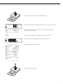
Operating the Combics 2
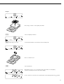
Example:
00
8
10
Place empty container on the weighing instrument
Comb
ics 2
-
n
CF
0
T
RE
F
Fn
OK
)
Tare the weighing instrument
00
8
10
r (repeatedly, if necessary)
00
Set the desired reference sample quantity (in this example, 20)
8
20
Place the corresponding number of pieces (20) in the container
Comb
ics 2
-
n
CF
0
T
RE
F
Fn
OK
O
Confirm reference sample weight
20
8
20
24
Add more parts to the container (in this example, 18 pcs)
Comb
ics 2
-
n
CF
0
T
RE
F
Fn
OK
38
8
20
0pt 38
8
0pt is displayed if automatic reference sample updating is enabled
20
w
Toggle the display from piece count to weight
w < 2 sec.
Toggle to Info mode
Piece count is displayed
w
Toggle to the next display mode
Reference sample quantity is displayed
w (> 2 sec)
Return to weighing mode
p
Print results
G#
T
N
+
+
+
610.0 g
200.0 g
410.0 g
Qnt
38 pcs
-------------------25
Operating the Combics 2
Neutral Measurement Z nm
When the Neutral Measurement
application is selected, you can use your
weighing instrument to measure the
length, surface and volume of parts that
have roughly the same specific weight.
The o symbol is displayed as the weight
unit.
Features:
– Store the weight on the weighing
instrument as reference weight
– Enter reference weight using a bar code
scanner
– Enter tare weight using a bar code
scanner
– Toggle the display between weight
and calculated value by pressing w
– Info mode for display of reference
weight by pressing w (> 2 sec)
To calculate the result correctly, the
average weight of a reference quantity
must be known (in the example below,
the reference is 1 meter of electrical
cable). There are 2 ways to do this with
the Combics:
3. 5.
Minimum Load for Automatic Taring
and Automatic Printing
3. 5. 1 * 1 digit
3. 5. 2 2 digits
3. 5. 3 5 digits
3. 5. 4 10 digits
3. 5. 5 20 digits
3. 5. 6 50 digits
3. 5. 7 100 digits
3. 5. 8 200 digits
3. 5. 9 500 digits
3. 5.10 1000 digits
3. 6.
Minimum Load for Initialization
3. 6. 1 * 1 digit
3. 6. 2 2 digits
3. 6. 3 5 digits
3. 6. 4 10 digits
3. 6. 5 20 digits
3. 6. 6 50 digits
3. 6. 7 100 digits
3. 6. 8 200 digits
3. 6. 9 500 digits
3. 6.10 1000 digits
3. 7.
Automatic Taring:1st Weight Tared
3. 7. 1 * Off
3. 7. 2 On
3. 8.
Start Application with Most Recent
Application Data when Combics
is Switched On
3. 8. 1 Automatic (on)
3. 8. 2 * Manual (off)
3. 9.
Resolution for Calculation
of Reference Value
3. 9. 1 * Display resolution
3. 9. 2 Display resolution + 1
decimal place
3. 9. 3 Display resolution + 2
decimal places
3. 9. 4 Internal resolution
3.10.
Decimal Places for Display of Results
3.10. 1 * None
3.10. 2 1 decimal place
3.10. 3 2 decimal places
3.10. 4 3 decimal places
3.11.
Storage Parameter
3.11. 1* At stability
3.11. 2 At increased stability
3.13.
Reference Weighing Instrument
3.13. 1* Off
3.13. 2 WP1
3.13. 3 WP2
– By placing the number of parts defined
for the reference value on the weighing
instrument and pressing O to store
the average piece weight.
The reference value is shown in the
numeric display, and can be changed
by pressing r.
How the reference weight is calculated
depends on the menu setting for resolution (3.9). Either the value is rounded
off in accordance with the display
resolution, or the display resolution is
increased 10-fold (+1 decimal place) or
100-fold (+ 2 decimal places), or maximum internal resolution is applied.
– By entering the reference weight (i.e.,
the weight of one piece) using a bar
code scanner (menu setting: “Setup>
Bar code > Store value as reference
(ref)"). In this case, the value is stored
as a reference automatically, without
pressing the O key.
This value remains active in the reference
memory until you delete it by pressing
c, overwrite it or until you select
a different application. It also remains
stored after you switch off the Combics.
26
Application Parameters: Neutral Measurement
Storage Parameter
The reference weight is saved when
the weighing instrument has stabilized.
“Stability" is defined as the point at
which fluctuation of a measured value
lies within a defined tolerance range.
The narrower the tolerance range, the
more stable the weighing instrument
is at “stability." This setting is also
applied when you zero the weighing
instrument.
Under menu item 3.11 you can
determine whether the value is saved
“At stability" (normal tolerance range)
or “At increased stability" (narrower
tolerance range).
If you select “At increased stability,"
the average piece weight stored will be
more accurate and the results more
reproducible, but the response time of
the weighing instrument might be
longer.
Decimal Places for Display of Results
In neutral measurement, not only whole
numbers but also decimal numbers
(for example, 1.25 o electrical cabling)
can be displayed. The number of decimal
places displayed in neutral measurement
is configured under menu item 3.10.
The measured result can be displayed
with 0, 1, 2 or 3 decimal places.
–
–
–
–
Minimum Load for Initialization
The minimum load for initialization
is configured under menu item 3.6.
If the load exceeds this limit, the
weighing instrument can be initialized.
If the load is too light, the following
will occur when you try to save a value:
The error code inf 29 is displayed
A warning signal is emitted
(double-beep)
The weighing instrument is not
initialized
The preset reference value is stored
Neutral Measurement with
Two Weighing Instruments
You can use two weighing instruments
simultaneously with the Neutral Measurement application. When using two
instruments, you can choose from the
following operating modes:
– Neutral measurement with two
equivalent weighing instruments
– Neutral measurement with one
reference weighing instrument and
one measurement platform
Neutral Measurement with Two Equivalent Weighing Instruments
Use this mode when samples of widely
varying weight are measured at one
workstation. Measure the lighterweight pieces on one weighing instrument and the heavier pieces on another.
When you press n to toggle from one
weighing instrument to the other, the
application is re-initialized.
You can define which of the two
weighing instruments is active in the
display when the Combics is switched
on (menu item 8.11). This is the first
weighing instrument active when you
switch on the Combics, regardless of
the setting for automatic initialization of
the Neutral Measurement application.
Neutral Measurement with One
Reference Weighing Instrument and
One Measuring Platform
In this mode, a high-resolution weighing
instrument with a relatively low maximum
capacity is used as a reference weighing
instrument. The measuring platform
has a high capacity, but a relatively low
resolution.
This allows you to both determine the
reference value with high resolution;
i.e., very precisely, and to measure large
samples, without requiring an expensive
high-resolution, high-capacity weighing
platform.
Specify which weighing instrument is the
reference instrument under menu item
3.13. The system toggles automatically
to the reference instrument for initialization (Ref is shown in the main display). Following initialization, the system
toggles to the measuring platform.
27
Operating the Combics 2
Example:
Determine the length of an amount of electrical cable after weighing in the defined reference unit value
00
8
1
Place empty container on the weighing instrument
Comb
ics 2
-
n
CF
0
T
RE
F
Fn
OK
)
Tare the weighing instrument
00
8
1
r (repeatedly, if necessary)
00
Set the desired reference value (in this example, 2)
8
2
Place a sample corresponding to the reference quantity in the container
(in this example, 2 meters of electrical cable)
Comb
ics 2
-
n
CF
0
T
RE
F
Fn
OK
O
Confirm reference sample weight
2
8
2
28
Remove the reference material and place the sample to be measured on the
weighing instrument (in this example, 8 meters of electrical cable
Comb
ics 2
-
n
CF
0
T
RE
F
Fn
OK
8
8
2
p
G#
T
N
Print results
+
+
+
734.1 g
200.0 g
534.1 g
Qnt
8 o
--------------------
29
Operating the Combics 2
Checkweighing O
When the Checkweighing application is
selected, you can check whether sample
weights correspond to a specified target
weight; i.e., whether the weight on the
weighing instrument is within a given
tolerance range. The tolerance range
is defined by upper and lower limits.
The result is displayed in the main
indicator, in the bar graph and by colorcoded LEDs.
–
–
–
–
–
–
–
–
–
–
30
Features:
The target value can be taken over
as a weighed value from a weighing
instrument, and the tolerance limits
are defined as a perceptual deviation
from the target value. The following
percentages can be selected as the
deviation: 0.1%, 0.2%, 0.5%, 1%, 1.5%,
2%, 3%, 5% or 10%.
The target value, lower tolerance
limit (minimum) and upper tolerance
limit (maximum) can be taken over
as weighed values from the weighing
instrument.
Target and tolerance limits checked
during input; values must conform to:
Upper limit > Target > Lower limit >
1 digit
Checkweighing range: either 30%
to 170% of the target, or from 10%
to infinity
Application started automatically
with most recent application data
when Combics switched on
Automatic taring
Automatic printing
Toggle the display between weight
and tolerances limits by pressing w.
When tolerances are displayed, weights
exceeding the tolerance limits are
shown with “LL" (too low) or “HH"
(too high).
Digital input/output interface
Info mode for display of tolerance limits
by pressing w (> 2 sec)
Checkweighing entails comparing
the current weight value to a defined
target. The target value has a tolerance
range which can be entered either as
an absolute value or percentage (menu
item 4.5).
– Entering the tolerance range as
an absolute value (weighed value)
(menu item 4.5.1):
Start initialization by pressing O;
the middle segments of the bar graph
flash to prompt the placement of the
weight on the weighing instrument.
Place the weight on the instrument and
press O to store.
The bar graph segment for the lower
limit flashes to prompt the weight for
lower limit. Place the weight on
the weighing instrument and press
O to store.
The bar graph segment for the upper
limit flashes to prompt the weight for
upper limit. Place the weight on the
weighing instrument and press O to
store.
– Entering the tolerance range as
a percentage (menu item 4.5.2):
A value for the percentage is shown in
the numeric display (lower right-hand
corner) together with the “%" sign.
Press r to change the percentage
value (0.1%, 0.2%, 0.5%, 1%, 1.5%, 2%,
3%, 5%, 10%).
Start initialization by pressing O;
the middle segments of the bar graph
flash to prompt the placement of the
weight on the weighing instrument.
Place the weight on the instrument and
press O to store. To can change the
percentage value for the tolerance limits
again before the target value is stored,
press r.
Before the new initialization, the
previous initialization values must be
deleted by pressing c.
Application Parameters: Checkweighing
3. 5.
Minimum Load for Automatic Taring and
Automatic Printing
3. 5. 1 * 1 digit
3. 5. 2 2 digits
3. 5. 3 5 digits
3. 5. 4 10 digits
3. 5. 5 20 digits
3. 5. 6 50 digits
3. 5. 7 100 digits
3. 5. 8 200 digits
3. 5. 9 500 digits
3. 5.10 1000 digits
3. 7.
Automatic Taring: 1st Weight Tared
3. 7. 1 * Off
3. 7. 2 On
3. 8.
Start Application with Most Recent
Application Data when Combics
is Switched On
3. 8. 1 Automatic (on)
3. 8. 2 * Manual (off)
4. 2.
Checkweighing Range
4. 2. 1 * 30% to 170%
4. 2. 2 10% to infinity
4. 3.
Activate Control Line for “Set" as:
4. 3. 1 * “Set" output
4. 3. 2 Ready to operate
4. 4.
Activation of Outputs
4. 4. 1 Off
4. 4. 2 Always active
4. 4. 3 Active at stability
4. 4. 4 * Active within checkweighing
range
4. 4. 5 Active at stability within the
checkweighing range
4. 5.
Parameter Input
4. 5. 1 * Min, max, target
4. 5. 2 Only target with percent limits
4. 6.
Automatic Printing
4. 6. 1 * Off
4. 6. 2 On
4. 6. 3 Only values within
tolerance
4. 6. 4 Only values outside
tolerance
Display
The result of a measurement is shown
either as a weight value or in relation
to the target. You can toggle between
these two display modes by pressing
w.
– Weight display mode:
The main display always shows the
weight value, even if the value is
outside the tolerance range.
The bar graph is displayed with symbols
indicating lower limit, target and upper
limit. It shows a logarithmic display of
the current load if the weight is anywhere from 0 to the minimum load, and
a linear display for weights beyond that
range.
The LEDs indicate the following:
Yellow: weight value >
upper tolerance limit
Green: weight value is
within tolerance
Red:
weight value <
lower tolerance limit
If no LED lights up:
– the application is not completely
initialized, or
– the weight value is outside
the checkweighing range
(see menu item 4.2)
– the weighing instrument has
not stabilized
– Tolerance limit display mode:
As “Weight display mode" above,
with the exception that:
– LL is shown on the main display
if the weight value is lower than
the target, and
– HH is shown on the main display
if the weight value is higher than
the target
–
–
–
–
–
–
–
–
–
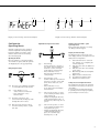
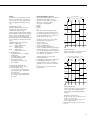
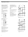
Digital Input/Output Interface
The Checkweighing application supports
the digital input/output interface.
There are 4 control lines, or outputs,
which are activated as follows
(also refer to the diagram):
Lighter
Equal
Heavier
Set
The “SET" output normally changes
its voltage level when the load is near
the target weight. Alternatively, you can
assign the “Ready-for-use" function to
this port (menu item 4.3.2).
Under menu item 4.4, you can define
whether these control ports are
inactive (4.4.1)
always active (4.4.2)
active at stability (4.4.3)
active within the check range, or
active at stability within the check range
For example, you can use this function
to show the weighed or measured result
on a simple external indicator, similar to
the 3 LEDs on the Combics 2.
All data output ports have a high
voltage level when:
– the application has not been initialized,
– the weighing instrument is not at
stability and one of the “at stability…"
parameters, (4.4.3 or 4.4.5) is selected,
or
– the weight is not within the check
range (4.4.4).
Checking Range
30 % Target weight 170%
Lower
limit
Upper
limit
Lighter
Equal
Heavier
Set
Operative
Digital I/O Interface
“SET" control line: set and control lines:
Always active/Active at stability
Checking Range
30 % Target weight 170%
Lower
limit
Upper
limit
Lighter
Equal
Heavier
Set
Operative
Digital I/O Interface
“SET" control line: set and control lines:
active within checkweighing range/
Active within checkweighing range at
stability
Output line specifications:
– In the inactive state, the levels are set to
“high:” >3.7 V/+4 mA
– In the active state, the levels are set to
“low:” <0.4 V/–4 mA
! The output lines are not short-circuit
proof!
31
Operating the Combics 2
Example:
Initialize the Checkweighing application by taking over the weighed value as target; select percentage to define tolerance range
(menu item 4.5.2)
c
Delete any existing initialization data
O
Begin initialization
The middle segments of the bar graph flash to prompt the placement of the weight
on the weighing instrument
Place the weight for the target on the weighing instrument (in this example, 100.0 g)
Comb
ics 2
-
n
CF
0
T
RE
F
Fn
OK
1000
8
10
r repeatedly, if necessary
1000
Select the desired percentage for tolerance limits (in this example, 5%)
8
15
O
Optional:
32
Store target and calculate tolerance range based on the selected percentage
w < 2 sec.
Toggle to Info mode to view stored values
1000
8
Target value is displayed
inf
w
Optional:
Toggle to the next display mode
5
8
Percentage for limits is displayed
Inf
w
Optional:
Toggle to the next display mode
950
8
Weight value for the lower limit (minimum) is displayed
inf
Optional:
w
Toggle to next display mode (weight value for the upper limit is displayed)
Optional:
w > 2 sec
Exit the Info mode
Unload weighing instrument
Comb
ics 2
-
n
CF
0
T
RE
F
Fn
OK
00
33
Operating the Combics 2
Example:
Check the weight of a sample; use Tolerance Limit display mode
Place a load of unknown weight on the weighing instrument
Comb
ics 2
-
n
CF
0
T
RE
F
Fn
OK
If the weight is under the lower tolerance limit, LL is shown in the tolerance limit display
(load is too light) (the weight display shows the measured weight value)
1032
hhx
p
If the weight is within the tolerance range (in this example, 103.2 g),
the weight value is displayed
If the weight is over the upper tolerance limit, HH is shown in the tolerance limit display
(load is too heavy) (the weight display shows the measured weight value)
Print results
ACE HARDWARE
GOETTINGEN
19.03.2002
15:43
-------------------Setp +
100.0 g
Min
+
95.0 g
Max
+
105.0 g
Printout
G#
T
N
Gross weight
Tare weight
Net weight
+
+
+
103.2 g
0.0 g
103.2 g
Lim
+
3.20 %
W.Diff+
3.2 g
--------------------
Target value
Minimum
Maximum
Percentage of deviation from target*
Absolute difference from target
* In Tolerance Limit display mode:
If the weight is lighter than the target, the display shows: Stat
If the weight is heavier than the target, the display shows: Stat
34
LL
HH
Operating the Combics 2
Classification O cl
With the Classification application,
you can determine whether the weight
of a given sample lies within the limits
of a defined weight class.
Features:
– Configure 3 or 5 classes (menu item 4.8)
– Define contiguous classes
– Define classes that cover the entire
weighing range of the weighing
instrument
– Range below the specified minimum
load is designated “Class 0"
– Define the upper limit of a given
class by storing weight on weighing
instrument or by entering a weight
value and a percentage
– Show the current weight in the
main display as a weight value or as
belonging to a certain class
– Class of current weight also indicated
by 1 LED (when using 3 classes)
or 2 LEDs (when using 5 classes) 2 LEDs
(when using 5 classes)
– Toggle the display between weight
and class by pressing w.
– Digital input/output interface
– Info mode for display of class limits by
pressing w (> 2 sec)
To use the Classification application,
you need to enter the delimiters that
separate one class from another.
Application Parameters: Classification
3. 5.
Minimum Load for Automatic Taring
and Automatic Printing
3. 5. 1 * 1 digit
3. 5. 2 2 digits
3. 5. 3 5 digits
3. 5. 4 10 digits
3. 5. 5 20 digits
3. 5. 6 50 digits
3. 5. 7 100 digits
3. 5. 8 200 digits
3. 5. 9 500 digits
3. 5.10 1000 digits
3. 6.
Minimum Load for Initialization and
Defining the Class 1 Lower Limit
3. 6. 1 * 1 digit
3. 6. 2 2 digits
3. 6. 3 5 digits
3. 6. 4 10 digits
3. 6. 5 20 digits
3. 6. 6 50 digits
3. 6. 7 100 digits
3. 6. 8 200 digits
3. 6. 9 500 digits
3. 6.10 1000 digits
3. 7.
Automatic Taring: 1st Weight Tared
3. 7. 1 * Off
3. 7. 2 On
3. 8.
Start Application with Most Recent
Application Data when Combics
is Switched On
3. 8. 1 Automatic (on)
3. 8. 2 * Manual (off)
4. 3.
Activate Control Line for “Set" as:
4. 3. 1 * “Set" output
4. 3. 2 Ready to operate (for process
control systems)
4. 7.
Activation of Outputs
4. 7. 1 Off
4. 7. 2 Always active
4. 7. 3 * Active at stability
4. 8.
Number of Classes
4. 8. 1 * 3 classes
4. 8. 2 5 classes
4. 9.
Parameter Input
4. 9. 1 * Weight values
4. 9. 2 Percentage
4.10.
Automatic Printing
4.10. 1* Off
4.10. 2 On
– Start the initialization by pressing O.
The lower limit of Class 1 is defined
by the preset minimum load.
Weight values below minimum load
are classified as belonging to Class 0, in
part to prevent an unloaded weighing
instrument from displaying a value that
designates a class.
You can enter the other class delimiters
as absolute values or percentages
(menu item 4.9).
– Entering the class delimiters
as absolute values (weighed values)
(menu item 4.9.1):
For each upper limit (except that of
the highest class), place a load on the
weighing instrument and press O to
store it as the upper limit of a class.
The bar graph and the numeric
display show the limit currently being
configured.
Each time you store a value for an
upper limit, a check is run to make sure
the value is equal to or greater than
the upper limit of the previous class.
If the value is invalid, an acoustic signal
is emitted; the limit must be entered
again.
– Entering delimiters as percentages
(menu item 4.9.2):
Define the upper limit of Class 1 by
placing the corresponding weight on
the weighing instrument and pressing
O. The value is equal to 100 %.
The upper limit of Class 2 is equal
to 100 % plus the percentage you select
by pressing r (1, 2, 5, 10, 15, 30, 50,
70, 100, 150, 199 %).
Example: A load of 100 g is stored from
the weighing instrument as the upper
limit of Class 1. The value 15% is then
entered, defining the upper limit of
Class 2 as 115 g.
In this case, the weight ranges when
working with 5 classes are:
Class 0: up to the minimum load
Class 1: Minimum load – 100 g
Class 2: 100 g – 115 g
Class 3: 115 g – 130 g
Class 4: 130 g – 145 g
Class 5: 145 g – maximum capacity
Before a new initialization,
the previous initialization values must
be deleted by pressing c.
35
Operating the Combics 2
Minimum Load for Initialization and
Defining the Class 1 Lower Limit
The minimum load defines the
lower limit for Class 1 (i.e., the delimiter
between Classes 0 and 1). The application can only be initialized (to define
the upper limit of Class 1) when
the load on the weighing instrument
exceeds the minimum load.
Display
The result of a given measurement
is shown as either a weight value
or the class number. You can toggle
between these two display modes
by pressing w.
– Weight display; 3 classes:
The current weight is shown in the
display; for example: 108.7 g
Class 1 Bar graph:
Numeric display: 1
LED: red is lit
Class 2 Bar graph:
Numeric display: 2
LED: green is lit
Class 3 Bar graph:
Numeric display: 3
LED: yellow is lit
– Weight display; 5 classes
The current weight is shown in the
display; for example: 108.7 g
Class 1 Bar graph:
Numeric display: 1
LED: red is lit
Class 2 Bar graph:
Numeric display: 2
LED: red and green are lit
Class 3 Bar graph:
Numeric display: 3
LED: green is lit
Class 4 Bar graph:
Numeric display: 4
LED: green and yellow are lit
Class 5 Bar graph:
Numeric display: 5
LED: yellow is lit
– Class display; 3 classes
The current class is shown in the
display; for example: class 1 and the
bar graph indicates the current weight.
The LEDs are lit as for the weight
display described above.
– Class display; 5 classes
The current class is shown in the
display; for example: class 1, and the
bar graph indicates the current weight.
The LEDs are lit as for the weight
display described above.
36
–
–
–
–
Digital Input/Output Interface
The Classification application supports
the digital input/output-interface.
There are 4 control lines, or outputs,
which are activated as follows (also refer
to the diagram):
Lighter
Equal
Heavier
Set
The “Set" line usually indicates that the
minimum load is exceeded. Alternatively,
you can assign the “Ready-for-use"
function to this port.
Under menu item 4.7, you can define
whether these control ports are
– inactive (4.7.1),
– always active (4.7.2), or
– active at stability (4.7.3).
This makes it possible, for example,
to connect a simple indicator for
weighing or calculation results, similar
to the 3-segment checkweighing
display on the Combics, or control
an automatic process.
Min. load
Max. load
Class
2
1
3
Class 1
Class 2
Class 3
Set
Operative
Digital I/O Interface
Control lines when working with 3
classes
Min. load
1
2
Max. load
Class
3
4
5
Classes 1/2
Classes 2/3/4
Classes 4/5
Set
Operative
Digital I/O Interface
Control lines when working with
5 classes
Example:
Initialize the Classification application by taking over weighed values (menu item 4.9.1) to define 3 classes (menu item 4.81.)
c
Delete any existing initialization data
O
Begin initialization
The minus sign of the bar graph flashes to prompt the weight for the upper limit
of the first class. A “1" is shown in the numeric display.
Place the weight for the upper limit of the first class on the weighing instrument
(in this example, 10.0 g)
Comb
ics 2
-
n
CF
0
T
RE
F
Fn
OK
O
Store the weight value as the upper limit for the first class
The middle segments of the bar graph flash to prompt the placement
of the weight for the upper limit of the second class on the weighing instrument.
A “2" is shown in the numeric display.
Place the weight for the upper limit of the second class on the weighing instrument
(in this example, 20.0 g)
Comb
ics 2
-
n
CF
0
T
RE
F
Fn
OK
37
Operating the Combics 2
O
Store the weight value as the upper limit for the second class
When initialization is complete, the display shows the class to which the weight on the
weighing instrument belongs.
Optional:
w < 2 sec.
Toggle to Info mode to view stored values
Upper limit of Class 1 is displayed
Optional:
w
Toggle to the next display mode
Upper limit of Class 2 is displayed
w
Exit the Info mode
Unload weighing instrument
Comb
ics 2
-
n
CF
0
T
RE
F
Fn
OK
00
8
0
38
Example:
Determine the class of a given weight
Place a load of unknown weight on the weighing instrument
Comb
ics 2
-
n
CF
0
T
RE
F
Fn
OK
The display shows which class the weight falls into; in this example, Class 2 (10 g – 20 g)
w
Toggle display to weight readout
The weight of the load is shown (in this example, 17.3 g)
p
Print results
PET STORE
GOETTINGEN
05.03.2002
09:43
-------------------Lim1 +
10.0 g
Lim2 +
20.0 g
Printout
G#
T
N
Gross weight
Tare weight
Net weight
+
+
+
17.3 g
0.0 g
17.3 g
Class
2
--------------------
Upper limit, Class 1
Upper limit, Class 2
Weight class
39
Operating the Combics 2
Weighing in Percent L
With the Weighing in Percent application, you can use your weighing
instrument to obtain weight readouts
in percent which are in proportion to
a reference weight. The L symbol is
displayed as the weight unit.
Features:
– Store the weight on the weighing
instrument as reference weight
– Enter reference weight using a bar
code scanner
– Enter tare weight using a bar code
scanner
– Toggle the display between percentage
and weight by pressing w
– Show percentage as loss or residue
– Display up to 3 decimal places
– Info mode for display of reference
weight by pressing w (> 2 sec)
To determine the weight of a sample
relative to a reference weight, you
must enter the reference weight in the
weighing instrument. There are 2 ways
to do this with the Combics:
3. 5.
Minimum Load for Automatic Taring
and Automatic Printing
3. 5. 1 * 1 digit
3. 5. 2 2 digits
3. 5. 3 5 digits
3. 5. 4 10 digits
3. 5. 5 20 digits
3. 5. 6 50 digits
3. 5. 7 100 digits
3. 5. 8 200 digits
3. 5. 9 500 digits
3. 5.10 1000 digits
3. 6.
Minimum Load for Initialization
3. 6. 1 * 1 digit
3. 6. 2 2 digits
3. 6. 3 5 digits
3. 6. 4 10 digits
3. 6. 5 20 digits
3. 6. 6 50 digits
3. 6. 7 100 digits
3. 6. 8 200 digits
3. 6. 9 500 digits
3. 6.10 1000 digits
3. 7.
Automatic Taring: 1st Weight Tared
3. 7. 1 * Off
3. 7. 2 On
3. 8.
Start Application with
Most Recent Application Data
when Combics is Switched On
3. 8. 1 Automatic (on)
3. 8. 2 * Manual (off)
3. 9.
Resolution for Calculation of Reference
Value
3. 9. 1 * Display resolution
3. 9. 2 Display resolution +1 decimal
place
3. 9. 3 Display resolution +2 decimal
places
3. 9. 4 Internal resolution
3.10.
Decimal Places for Display of Results
3.10. 1* None
3.10. 2 1 decimal place
3.10. 3 2 decimal places
3.10. 4 3 decimal places
3.11
Storage Parameter
3.11. 1* At stability
3.11. 2 At increased stability
3.13.
Reference Weighing Instrument
3.13. 1* No reference instrument selected
3.13. 2 WP1
3.13. 3 WP2
3.15.
Display of calculated value
3.15. 1* Residue
3.15. 2 Loss
– By placing the amount of reference
material on the weighing instrument
specified by the reference percentage
and pressing O to calculate the
average and store the value.
The reference percentage is shown
in the numeric display, and can be
changed by pressing r.
How the reference weight is calculated
depends on the menu setting for
resolution (3.9). Either the value is
rounded off in accordance with the
display resolution, or the display
resolution is increased 10-fold
(+1 decimal place) or 100-fold
(+2 decimal places), or maximum
internal resolution is applied.
– By entering the reference weight (i.e.,
the weight of 100%) using a bar code
scanner (menu setting: “Setup> Bar
code > Store value as reference (ref)").
In this case, the value is stored as
a reference automatically, without
pressing the O key.
This value remains active in the
reference memory until you delete it
by pressing c, overwrite it or until
you select a different application.
It also remains stored after you switch
off the Combics.
40
Application Parameters: Weighing in Percent
Storage Parameter
The reference weight is saved when
the weighing instrument has stabilized.
“Stability" is defined as the point at
which fluctuation of a measured value
lies within a defined tolerance range.
The narrower the tolerance range, the
more stable the weighing instrument
is at stability. This setting is also applied
when you zero the weighing instrument.
Under menu item 3.11 you can
determine whether the value is saved
“At stability" (normal tolerance range)
or “At increased stability" (narrower
tolerance range).
If you select “At increased stability,"
the reference weight stored will be more
accurate and the results more reproducible, but the response time of the
weighing instrument might be longer.
–
–
–
–
Minimum Load for Initialization
The minimum load for initialization
is configured under menu item 3.6.
If the load exceeds this limit, the
weighing instrument can be initialized.
If the load is too light, the following
will occur when you try to save a value:
The error code inf 29 is displayed
A warning signal is emitted
(double-beep)
The weighing instrument is not
initialized
The preset reference percentage is
stored
Weighing in Percent with
Two Weighing Instruments
You can use two weighing instruments
simultaneously with the Weighing in
Percent application. When using two
instruments, you can choose from
the following operating modes:
– Weighing in Percent with two equivalent weighing instruments
– Weighing in Percent with one reference
weighing instrument and one weighing
platform
Display
With the Weighing in Percent application,
the result can be displayed as a remainder
or loss. This is configured in Setup under
menu item 3.15.
Equations:
Residue= Current weight/
100% weight* 100
Loss=
(Current weight –
100% weight) /
100% weight * 100
Weighing in Percent with Two Equivalent Weighing Instruments
Use this mode when samples of
widely varying weight are measured at
one workstation. Measure the lighterweight pieces on one weighing instrument and the heavier pieces on another.
When you press n to toggle from
one weighing instrument to the other,
the application is re-initialized.
You can define which of the two weighing instruments is active in the display
when the Combics is switched on (menu
item 8.11). This is the first weighing
instrument active when you switch on
the Combics, regardless of the setting
for automatic initialization of the
Weighing in Percent application.
Weighing in Percent with
One Reference Weighing Instrument
and One Weighing Platform
In this mode, a high resolution weighing instrument with a relatively low
maximum capacity is used as a reference weighing instrument. The
measuring platform has a high capacity,
but a relatively low resolution.
This allows you to both determine the
reference value with high resolution;
i.e., very precisely, and to measure large
samples, without requiring an expensive
high-resolution, high-capacity weighing
platform.
Specify which weighing instrument
is the reference instrument under menu
item 3.13. The system toggles automatically to the reference instrument for
initialization (Ref is shown in the main
display). Following initialization, the
system toggles to the measuring platform.
41
Operating the Combics 2
Example:
00
8
1000
Place empty container on the weighing instrument
Comb
ics 2
-
n
CF
0
T
RE
F
Fn
OK
)
Tare the weighing instrument
00
8
1000
r (repeatedly, if necessary)
00
Set the desired percentage (in this example, 50%)
8
500
Place reference material corresponding to the reference percentage in the container
Comb
ics 2
-
n
CF
0
REF
T
Fn
OK
O
Confirm the reference weight
50
8
50
42
Remove the reference material and place the sample to be measured on the
weighing instrument
Comb
ics 2
-
n
CF
0
T
RE
F
Fn
OK
79
8
The percentage of the reference weight equal to the sample is displayed
50
p
G#
T
N
Print results
+
+
+
641.2 g
200.0 g
441.2 g
Residue
Prc
+
21.00 %
-------------------G#
T
N
+
+
+
641.2 g
200.0 g
441.2 g
Loss
D
79.00 %
--------------------
43
Operating the Combics 2
Averaging
(Animal Weighing) V
With the Averaging application, you
can use your weighing instrument
for calculating weights as the average
of a number of individual weighing
operations. These individual operations
are also known as “subweighing
operations."
This function is used to determine
weights under unstable ambient
conditions or for weighing unstable
samples (such as live animals).
Features:
– Averaging started manually or
automatically
– Press the r key to select the desired
number of subweighing operations
– Toggle the display between last result
and current weight by pressing w
A number of subweighing operations
are required to form the basis for
calculation of an average weight. These
are performed consecutively as soon as
the weight of one sample differs from
that of the previous sample by less than
the preset deviation.
The value for this deviation is entered
in the Application settings (3.19) as
a percentage. This value and the minimum load must be reached to start
the averaging routine.
Whether averaging starts automatically
or manually is defined under menu
item 3.18.
There are four modes for calculating
average weights:
– Manual start with preset number
of subweighing operations
To use this mode, place the sample
or animal on the weighing instrument
and press O.
– Manual start with the number of subweighing operations entered manually
To use this mode, place the sample/
animal on the weighing instrument,
press r to enter the number of subweighing operations (10, 20, 30, 40)
and then press O.
44
– Automatic start with preset number
of subweighing operations
The subweighing operations begin
when the weight of the sample/animal
on the weighing instrument exceeds
the minimum load.
– Automatic start with the number
of subweighing operations entered
manually
To use this mode, press r and enter
the number of subweighing operations
before placing the sample or animal
on the weighing instrument. The
subweighing operations begin when
the weight of the sample/animal on
the weighing instrument exceeds the
minimum load.
If the “automatic tare" function is configured, the weight of the first load is
stored as the tare value, and averaging
begins only when the second load
is placed on the weighing instrument
(provided this weight exceeds the
preset minimum load).
Minimum Load for Automatic Start
The minimum load for automatic start
is configured under menu item 3.6.
If the load exceeds this limit, the averaging routine can begin.
Display
A calculated average value is shown
continuously on the main display.
The symbol ! is displayed.
Press w to toggle the display between
this result and the current weight value.
If the menu setting “Display is static
until unload threshold reached" (3.21.1)
is active, the program returns to the
weight display automatically when the
weighing instrument is unloaded; i.e.,
when the load is less than half the minimum load. The result of the most recent
averaging operation is not stored.
If the menu setting “Display is static
until c is pressed" (3.21.2) is active,
the average weight remains on the
weight display after the weighing
instrument is unloaded, until the c
key is pressed or until a new measurement series is started, whether manually
or automatically.
Application Parameters: Averaging (Animal Weighing)
3. 5.
Minimum Load for Automatic Taring
and Automatic Printing
3. 5. 1 * 1 digit
3. 5. 2 2 digits
3. 5. 3 5 digits
3. 5. 4 10 digits
3. 5. 5 20 digits
3. 5. 6 50 digits
3. 5. 7 100 digits
3. 5. 8 200 digits
3. 5. 9 500 digits
3. 5.10 1000 digits
3. 6.
Minimum Load
3. 6. 1 * 1 digit
3. 6. 2 2 digits
3. 6. 3 5 digits
3. 6. 4 10 digits
3. 6. 5 20 digits
3. 6. 6 50 digits
3. 6. 7 100 digits
3. 6. 8 200 digits
3. 6. 9 500 digits
3. 6.10 1000 digits
3. 7.
Automatic Taring: 1st Weight Tared
3. 7. 1 * Off
3. 7. 2 On
3. 8.
Start Application with Most Recent
Application Data when Combics
is Switched On
3. 8. 1 Automatic (on)
3. 8. 2 * Manual (off)
3.18.
Start of Averaging Routine
3.18. 1* Manual
3.18. 2 Automatic
3.19.
Animal Activity
3.19. 1 0.1 % of the animal/object
3.19. 2* 0.2% of the animal/object
3.19. 3 0.5 % of the animal/object
3.19. 4 1% of the animal/object
3.19. 5 2% of the animal/object
3.19. 6 5% of the animal/object
3.19. 7 10% of the animal/object
3.19. 8 20% of the animal/object
3.19. 9 50% of the animal/object
3.19.10 100 % of the animal/object
3.20.
Automatic Printout of Results
3.20. 1* Off
3.20. 2 On
3.21.
Static Display After Load Removed
3.21. 1* Display is static until unload
threshold reached
3.21. 2 Display is static until c is
pressed
Example:
00
8
10
Place empty container on the weighing instrument
Comb
ics 2
-
n
CF
0
T
RE
F
Fn
OK
)
Tare the weighing instrument
00
8
10
r (repeatedly, if necessary)
00
Set the desired number of measurements (in this example, 20)
8
20
Place 1st animal in bowl
Comb
ics 2
-
n
CF
0
T
RE
F
Fn
OK
O
Start measurement
240
8
Measurement starts as soon as all criteria are met. The number of subweighing
operations remaining is shown in the numeric display.
14
246
8
At the conclusion of the series, the calculated mean value is displayed with the ! symbol.
0
45
Operating the Combics 2
p
Print results
x-Net +
24.6 g
Unload weighing instrument
Comb
ics 2
-
n
CF
0
T
RE
F
Fn
OK
00
8
20
46
Once the weighing instrument is unloaded
(i.e., the load = less than 1/2 the minimum load), the current weight value is displayed.
Net-Total Formulation R
When the Net-Total Formulation
application is selected, you can weigh
in different components up to a defined
total. Each component is saved in the
net-total memory.
You can print out both the total
weight and the individual weights of
the components.
Features:
– Weigh in up to 199 components
in series
– Current component number shown
in the numeric display (indicating the
component to be added)
– Toggle the display between
“component mode" and “additive
mode" by pressing w:
– Component mode: Display the
weight of the component currently
on the instrument (for 1 second
after it is saved; then the instrument
is tared)
– Additive mode: Display the weight
of all components on the instrument
(after it is saved, the net weight
of the last component added is
displayed briefly)
– Toggle to a second weighing instrument
while weighing on the first
– Automatic printout of component
or total weight when weight is saved
– Automatic taring of container weight
– Minimum load for automatic taring
– Minimum load for storing values
– Display the value in totalizing memory
in the Info mode, accurately calculated
in the active weight unit, by pressing
and holding w
Application Parameters: Net-Total Formulation
3. 5.
Minimum Load for Automatic Taring
and Automatic Printing
3. 5. 1 * 1 digit
3. 5. 2 2 digits
3. 5. 3 5 digits
3. 5. 4 10 digits
3. 5. 5 20 digits
3. 5. 6 50 digits
3. 5. 7 100 digits
3. 5. 8 200 digits
3. 5. 9 500 digits
3. 5.10 1000 digits
3. 6.
Minimum Load for Automatic
Storage/Transfer of Values
3. 6. 1 * 1 digit
3. 6. 2 2 digits
3. 6. 3 5 digits
3. 6. 4 10 digits
3. 6. 5 20 digits
3. 6. 6 50 digits
3. 6. 7 100 digits
3. 6. 8 200 digits
3. 6. 9 500 digits
3. 6.10 1000 digits
3. 7.
Automatic Taring: 1st Weight Tared
3. 7. 1 * Off
3. 7. 2 On
3.17.
Automatic Individual or Component
Printout when Value Stored
3.17. 1 Off
3.17. 2* Generate printout with complete
standard configuration each time
O is pressed
3.17. 3 Generate printout with complete
standard configuration only once
when O is pressed
Minimum Load for Automatic Storage/
Transfer of Values
The minimum load for automatic
storage or transfer of weight values is
configured under menu item 3.6.
If the load exceeds this limit, the weight
currently displayed can be stored in nettotal memory.
Net-Total Formulation with
Two Weighing Instruments
This mode is used for weighing
large and small components at the
same time.
In this mode, you can toggle from
the small-component instrument
to the large-component instrument
during measurement. Once you toggle
to the large-component instrument,
the ( and ) keys are available
until a component is value is saved.
For example, you can tare a partiallyfilled container taken from the smallcomponent instrument on the large
component instrument.
The value in component memory on
the small-component instrument is
transferred to the large-component
instrument and the weight unit is converted, if necessary. The Component
and Additive display modes are both
available on the large-component
instrument.
The value read by the active instrument
is saved in component memory. The
displayed result is accurately calculated
in the active weight unit, for example:
1243 g
(from an instrument with 1 interval)
+ 1.40 kg
(from an instrument with 5 intervals)
= 2.643 kg (calculated result)
When you press c to stop a measurement series, the tare memories for
both weighing instruments are cleared,
unless the large-component instrument
is in SBI mode, in which case the
instrument is only tared.
47
Operating the Combics 2
Example:
Weigh in 3 components, display total weight after 2nd component (Additive mode)
Place empty container on the weighing instrument
Comb
ics 2
-
n
CF
0
T
RE
F
Fn
OK
500
8
Container weight a prompt for first component are shown
11
)
Tare the weighing instrument
00
8
11
Add the first component (in this example, 68.3 g)
Comb
ics 2
-
n
CF
0
T
RE
F
Fn
OK
The weight of the first component is displayed
O
ACE HARDWARE
GOETTINGEN
20.02.2002
15:10
-------------------Cmp001
68.3 g
Store the weight of the first component
Total data record is printed, as configured under menu item 7.7. or 7.8.
The header is printed only once
Component weight
The weighing instrument is tared automatically and the component counter value
is increased by one (prompting the next component)
48
Add the second component (in this example, 82.7 g)
Comb
ics 2
-
n
CF
0
T
RE
F
Fn
OK
The weight of the second component is displayed
O
Cmp002
Store the weight of the second component
82.7 g
Component weight is printed
The weighing instrument is tared automatically and the component counter value
is increased by one (prompting the next component)
w
Toggle to the Additive mode
The value displayed equals the weight of all components added up to now plus
the current weight
Add the third component (bringing the total to the desired target)
O
Cmp003
Store the weight of the third component
49.1 g
c
Component weight is printed
End the weighing-in operation
Total data record is printed, as configured under 7.9. or 7.10.
Ser.no
12345678
n
3
S-Comp+
200.1 g
Cont.T+
50.0 g
--------------------
Serial number of the weighing instrument
Number of components
Content of component memory
Content of tare memory (container weight)
Dotted line
49
Operating the Combics 2
Totalizing Σ
With the Totalizing application, you
can add weight values to the totalizing
memory. The number of values added
to the memory is also stored (“transaction counter").
Features:
– Weigh in up to 199 items
– Current transaction number displayed
in the text line (indicating the items
already added)
– Save weight values manually or
automatically
– Accurate calculation of total of weight
values from two weighing instruments
– Unfinished totalization stored in
battery-backed memory
– Toggle the display between current
weight and total value by pressing w:
– Totalizing mode: shows the value in
totalizing memory plus the current
weight; for filling to a defined total
– Automatic printout of component or
total weight when weight is saved
– Automatic taring of container weight
– Minimum load for automatic tare
– Minimum load for storing values
– Press and hold w to display the value
in totalizing memory (net, gross) in
the Info mode, accurately calculated in
the active weight unit.
50
The Combics has a totalizing memory
for adding individual net and gross
values. There are two ways to store
weight values in the totalizing memory:
- Manually, by pressing the O key.
The value is added to the value already
stored, and the transaction counter
value increases by one.
When a value is added manually,
the program does not check whether
the weighing instrument has been
unloaded since the last time the O
key was pressed.
– Automatically, when the weighing
instrument has stabilized and the
minimum load is exceeded (menu item
3.16.2).
The weighing instrument is considered
to be unloaded when the load is
less than 50% of the minimum load
(menu item 3.6.
The numeric display shows the
transaction counter.
Application Parameters: Totalizing
3. 5.
Minimum Load for Automatic Taring
and Automatic Printing
3. 5. 1 * 1 digit
3. 5. 2 2 digits
3. 5. 3 5 digits
3. 5. 4 10 digits
3. 5. 5 20 digits
3. 5. 6 50 digits
3. 5. 7 100 digits
3. 5. 8 200 digits
3. 5. 9 500 digits
3. 5.10 1000 digits
3. 6.
Minimum Load for Automatic Storage/
Transfer of Values
3. 6. 1 * 1 digit
3. 6. 2 2 digits
3. 6. 3 5 digits
3. 6. 4 10 digits
3. 6. 5 20 digits
3. 6. 6 50 digits
3. 6. 7 100 digits
3. 6. 8 200 digits
3. 6. 9 500 digits
3. 6.10 1000 digits
3. 7.
Automatic Taring: 1st Weight Tared
3. 7. 1 * Off
3. 7. 2 On
3. 8.
Start Application with Most Recent
Application Data when Combics
is Switched On
3. 8. 1 Automatic (on)
3. 8. 2 * Manual (off)
3.16.
Automatic Storage/Transfer of Value
3.16. 1* Off
3.16. 2 On
3.17.
Automatic Individual or Component
Printout when Value Stored
3.17. 1 Off
3.17. 2* Generate printout with complete
standard configuration each time
O is pressed
3.17. 3 Generate printout with complete
standard configuration only once
when O is pressed
Press the c key to clear the totalizing
memory. A printout is generated
automatically.
With the weighing instruments connected, you can add values from both
instruments to the totalizing memory.
The displayed result is accurately calculated in the active weight unit.
Example: 1.243 kg (measured on a
weighing instrument using 1 scale
interval) added to 1.40 kg (measured on
a weighing instrument using 5 scale
intervals) is displayed as 2.643 kg.
Minimum Load for Automatic
Storage/Transfer of Values
The minimum load for automatic
storage or transfer of weight values is
configured under menu item 3.6.
Once the load on the weighing instrument exceeds the specified minimum,
the measured value is stored or transferred automatically, if the operating
menu is configured for automatic
storage (menu item 3.16.2).
Display
Press w to toggle the display between
the weight currently on the weighing
instrument and the current weight value
plus the value in totalizing memory.
Press and hold w (> 2 sec) to toggle
to the Info mode. In the “Info" mode,
the total of gross weight values is
shown first. Press w again to show
the net value.
Press the w key again to show the
transaction counter in the main display.
Press w one more time to exit the
Info mode.
To exit the “Info" mode earlier, press
and hold w (> 2 sec).
Printout
Under menu item 3.17 you can configure
whether a printout is generated manually,
by pressing p (3.17.3), or automatically
when a weight value is stored in the
totalizing memory (3.17.2 or 3.17.3).
When you generate a printout manually
by pressing p, the transaction counter
value is not printed.
For automatic printouts, you can define
whether a printout is generated after each
individual transaction (3.17.2) or includes
all totalized components (3.17.3).
Each printout starts with the header lines
and the date and time, followed by a
dotted line, before printing the gross, tare,
net and transaction counter values.
The printout of components includes
the header lines and date and time only on
the first printout. Subsequent printouts
include only the gross, tare, net and transaction counter values (and serial number,
if configured).
The individual and component printouts
are configured under menu items 7.7
and 7.8.
The total data record is printed when
you clear the totalizing memory (by pressing the c key).
The total data record includes data from
the gross totalizing memory (*G), the net
totalizing memory (* N), the total transaction count (n) and a dotted line.
The fields selected under menu items
7.9. and 7.10. are printed every time the
c key is pressed, regardless of whether
individual or component printing is
configured.
51
Operating the Combics 2
Example:
Totalizing weight values with printout of components
Place the sample on the weighing instrument
Comb
ics 2
-
n
CF
0
T
RE
F
Fn
OK
1029
8
Weight value is displayed
0
O
Store weight value in totalizing memory
1029
8
Main display: Current weight on the weighing instrument
Numeric display: Transaction counter (in this example: 1)
1
SARTORIUS
GOETTINGEN
06.02.2002
12:15
-------------------G#
+
102.9 g
T
+
0.0 g
N
+
102.9 g
n
1
Unload the weighing instrument and then place the second sample on the instrument
Comb
ics 2
-
n
CF
0
T
RE
F
Fn
OK
Weight value is displayed
Optional:
w
Toggle to Totalizing mode
Main display: Totalizing memory content plus current weight
Numeric display: Transaction counter (in this example: 1)
O
52
Store weight value in totalizing memory
SARTORIUS
GOETTINGEN
06.02.2002
12:19
-------------------G#
+
215.2 g
T
+
0.0 g
N
+
215.2 g
n
2
Main display: Totalizing memory content plus current weight
Numeric display: Transaction counter (in this example: 2)
c
End totalizing
Total data record is printed, as configured under 7.9. or 7.10.
*G
+
318.1 g
*N
+
318.1 g
n
2
--------------------
Number of components
Contents of component memory
Contents of tare memory (container weight)
Dotted line
53
Configuration
Operating Menu Overview
You can configure the Combics to meet
individual requirements by entering user
data and setting selected parameters
in the operating menu.
The operating menu is a combination
of text levels and numeric codes.
= Setting/function available on Combics 1 plus only
= Setting/function available on Combics 2 only
= Setting/function available on Combics 1 plus and Combics 2 only
First level display
2nd level display
Function
W
Z
Z nm
V
O
O cl
L
R
Σ
Select and configure application programs
Basic Weighing Function
Counting
Neutral Measurement
Averaging (Animal Weighing)
Checkweighing
Classification
Weighing in Percent
Net-Total Formulation
Totalizing
off
gro net
2.unit
res 10
Define the function of k
No function
Gross/net toggling
Show 2nd weight unit
10-fold increased resolution
Menu
appl
Fn-key
Setup
wp1
com1
UNICOM
ctrl in
barcode
prtpro
Utilit
time
Date
code
Info
Lang
deutsch
english
us mode
franc
ital
espanol
54
Adapt Combics to user requirements
Settings for weighing instrument on WP1
Settings for the RS-232 interface
Settings for the optional second interface
Set the function of the universal input (control line)
Set the bar code scanner function
Settings for the printout
Settings for additional functions
Set the time
Set the date
Enter a password to protect menu settings
View device-specific information (service date, serial number, etc.)
Select language for calibration, adjustment and GMP printouts
German
English
English with U.S. date/time format
French
Italian
Spanish
Example: Change language from English to English with U.S. date/time format
e
Switch on the Combics
)
While all segments are lit, press the ) key
First level of menu for selecting the application program Appl is shown
k
Select the Lang menu item (press k repeatedly until Lang is displayed)
)
Select Lang device parameter
The currently active language is shown
k
Select the U.S. mode menu item
Press k repeatedly until U.S. mode is displayed)
)
Confirm this menu item
Return to menu level 2 to configure other menu settings, or
(
return to menu level 1 to configure other menu settings, or
) > 2 sec
exit the operating menu
55
Configuration
Example: Assign a password to protect the application program settings “Appl" and the device parameters “Setup"
from unauthorized changes (in this example: AB2)
e
Switch on the Combics
)
While all segments are lit, press the ) key
First level of menu for selecting the application program Appl is shown
k
)
k
Select the Setup menu item
(press k repeatedly until Setup is displayed)
Open the Setup menu
Select the Code menu item
(Press k repeatedly until code is displayed)
)
Open the password input menu item
p, p
Enter the first character using the p and k keys (in this example: A)
)
Store character
56
p, p, p
Enter the second character using the p and k keys (in this example: b)
)
Store character
k, k, k
Enter the third character using the p and k keys (in this example: 2)
)
Store character
To enter other characters, use the p and k keys and press ) to confirm
)
Store the password
(
Exit this menu level to configure other menu settings, or
) > 2 sec
Exit the operating menu
To delete a password:
Overwrite the old password with the new password, or enter a space as the password
and press ) to confirm.
57
Configuration
Operating Menu Overview (Parameters)
= Setting/function available on Combics 1 plus only
= Setting/function available on Combics 2 only
= Setting/function available on Combics 1 plus and Combics 2 only
* Factory setting
Menu
Appl
Application Programs
W
Basic Weighing Function
3. 5.
3. 5. 1 *
3. 5. 2
3. 5. 3
3. 5. 4
3. 5. 5
3. 5. 6
3. 5. 7
3. 5. 8
3. 5. 9
3. 5.10
Minimum Load for Automatic Taring and Automatic Printing
1 digit
2 digits
5 digits
10 digits
20 digits
50 digits
100 digits
200 digits
500 digits
1000 digits
3. 7. 1 *
3. 7. 2
Automatic Taring: 1st Weight Tared
Off
On
9. 1. 1
9. 1. 2 *
Factory Settings for All Application Programs
Yes
No
3. 7.
9. 1.
Z
Counting
3. 5.
Minimum Load for Automatic Taring and Automatic Printing
Numeric menu as for Weighing
3. 6.
3. 6. 1 *
3. 6. 2
3. 6. 3
3. 6. 4
3. 6. 5
3. 6. 6
3. 6. 7
3. 6. 8
3. 6. 9
3. 6.10
Minimum Load for Initialization
1 digit
2 digits
5 digits
10 digits
20 digits
50 digits
100 digits
200 digits
500 digits
1000 digits
3. 7. 1 *
3. 7. 2
Automatic Taring: 1st Weight Tared
Off
On
3. 8. 1
3. 8. 2 *
Start Application with Most Recent Application Data when Combics is Switched On
Automatic (on)
Manual (off)
3. 9. 1 *
3. 9. 2
3. 9. 3
3. 9. 4
Resolution for Calculation of Reference Value
Display resolution
Display resolution + 1 decimal place
Display resolution + 2 decimal places
Internal resolution
3.11. 1 *
3.11. 2
Storage Parameter
At stability
At increased stability
3.12. 1
3.12. 3 *
Reference Sample Updating
Off
Automatic
3.13. 1 *
3.13. 2
3.13. 3
Reference Weighing Instrument
No reference instrument selected
WP1
WP2
9. 1. 1
9. 1. 2 *
Factory Settings for All Application Programs
Yes
No
3. 7.
3. 8.
3. 9.
3.11.
3.12.
3.13.
9. 1.
58
appl
Z nm
Neutral Measurement
3. 5.
Minimum Load for Automatic Taring and Automatic Printing
Numeric menu as for Weighing
3. 6.
Minimum Load for Initialization
Numeric menu as for Counting
3. 7.
3. 7. 1 *
3. 7. 2
Automatic Taring: 1st Weight Tared
Off
On
3. 8. 1
3. 8. 2 *
Start Application with Most Recent Application Data when Combics is Switched On
Automatic (on)
Manual (off)
3. 9. 1 *
3. 9. 2
3. 9. 3
3. 9. 4
Resolution for Calculation of Reference Value
Display resolution
Display resolution + 1 decimal place
Display resolution + 2 decimal places
Internal resolution
3.10. 1 *
3.10. 2
3.10. 3
3.10. 4
Decimal Places for Display of Results
None
1 decimal place
2 decimal places
3 decimal places
3.11. 1 *
3.11. 2
Storage Parameter
At stability
At increased stability
3.13. 1 *
3.13. 2
3.13. 3
Reference Weighing Instrument
Off
To weighing instrument WP1
To weighing instrument WP2
9. 1. 1
9. 1. 2 *
Factory Settings for All Application Programs
Yes
No
3. 8.
3. 9.
3.10.
3.11.
3.13.
9. 1.
V
Averaging (Animal Weighing)
3. 5.
Minimum Load for Automatic Taring and Automatic Printing
Numeric menu as for Weighing
3. 6.
Minimum Load for Automatic Start
Numeric menu as for Counting
3. 7.
3. 7. 1 *
3. 7. 2
Automatic Taring: 1st Weight Tared
Off
On
3. 8. 1
3. 8. 2 *
Start Application with Most Recent Application Data when Combics is Switched On
Automatic (on)
Manual (off)
3.18. 1 *
3.18. 2
Start of Averaging Routine
Manual
Automatic
3.19. 1
3.19. 2 *
3.19. 3
3.19. 4
3.19. 5
3.19. 6
3.19. 7
3.19. 8
3.19. 9
3.19.10
Animal Activity
0.1 % of the animal/object
0.2% of the animal/object
0.5 % of the animal/object
1% of the animal/object
2% of the animal/object
5% of the animal/object
10% of the animal/object
20% of the animal/object
50% of the animal/object
100 % of the animal/object
3.20. 1 *
3.20. 2
Automatic Printout of Results
Off
On
3. 8.
3.18.
3.19.
3.20.
59
Configuration
appl
V
3.21.
3.21. 1 *
3.21. 2
Static Display After Load Removed
Display is static until unload threshold reached
Display is static until c is pressed
9. 1. 1
9. 1. 2 *
Factory Settings for All Application Programs
Yes
No
9. 1.
O
Checkweighing
3. 5.
Minimum Load for Automatic Taring and Automatic Printing
Numeric menu as for Weighing
3. 7.
3. 7. 1 *
3. 7. 2
Automatic Taring: 1st Weight Tared
Off
On
3. 8. 1
3. 8. 2 *
Start Application with Most Recent Application Data when Combics is Switched On
Automatic (on)
Manual (off)
4. 2. 1 *
4. 2. 2
Check Range
30% to 170%
10% to infinity
4. 3. 1 *
4. 3. 2
Activate Control Line for “Set" as:
“Set" output
Ready to operate (for process control systems)
4. 4. 1
4. 4. 2
4. 4. 3
4. 4. 4 *
4. 4. 5
Activation of Outputs
Off
Always active
Active at stability
Active within check range
Active at stability within the check range
4. 5. 1 *
4. 5. 2
Parameter Input
Min, max, target
Only target with percent limits
4. 6. 1 *
4. 6. 2
4. 6. 3
4. 6. 4
Automatic Printing
Off
On
Only values within tolerance
Only values outside tolerance
9. 1. 1
9. 1. 2 *
Factory Settings for All Application Programs
Yes
No
3. 8.
4. 2.
4. 3.
4. 4.
4. 5.
4. 6.
9. 1.
O CL
Classification
3. 5.
Minimum Load for Automatic Taring and Automatic Printing
Numeric menu as for weighing
3. 6.
Minimum Load for Initialization and Definition of “Class 1" Lower Limit
Numeric menu as for Counting
3. 7.
3. 7. 1 *
3. 7. 2
Automatic Taring: 1st Weight Tared
Off
On
3. 8. 1
3. 8. 2 *
Start Application with Most Recent Application Data when Combics is Switched On
Automatic (on)
Manual (off)
4. 3. 1 *
4. 3. 2
Activate Control Line for “Set" as:
“Set" output
Ready to operate
4. 7. 1
4. 7. 2
4. 7. 3 *
Activation of Outputs
Off
Always active
Active at stability
3. 8.
4. 3.
4. 7.
60
appl
O CL
4. 8.
4. 8. 1 *
4. 8. 2
Number of Classes
3 classes
5 classes
4. 9. 1 *
4. 9. 2
Parameter Input
Weight values
Percentage
4.10. 1 *
4.10. 2
Automatic Printing
Off
On
9. 1. 1
9. 1. 2 *
Factory Settings for All Application Programs
Yes
No
4. 9.
4.10.
9. 1.
L
Weighing in Percent
3. 5.
Minimum Load Automatic Taring and Automatic Printing
Numeric menu as for Weighing
3. 6.
Minimum Load for Automatic Initialization
Numeric menu as for Counting
3. 7.
3. 7. 1 *
3. 7. 2
Automatic Taring: 1st Weight Tared
Off
On
3. 8. 1
3. 8. 2 *
Start Application with Most Recent Application Data when Combics is Switched On
Automatic (on)
Manual (off)
3. 9. 1 *
3. 9. 2
3. 9. 3
3. 9. 4
Resolution for Calculation of Reference Value
Display resolution
Display resolution + 1 decimal place
Display resolution + 2 decimal places
Internal resolution
3.10. 1 *
3.10. 2
3.10. 3
3.10. 4
Decimal Places for Display of Results
None
1 decimal place
2 decimal places
3 decimal places
3.11. 1 *
3.11. 2
Storage Parameter
At stability
At increased stability
3.13. 1 *
3.13. 2
3.13. 3
Reference Weighing Instrument
Off
To weighing instrument WP1
To weighing instrument WP2
3.15. 1 *
3.15. 2
Display of Calculated Value
Residue
Loss
9. 1. 1
9. 1. 2 *
Factory Settings for All Application Programs
Yes
No
3. 8.
3. 9.
3.10.
3.11.
3.13.
3.15.
9. 1.
R
Net-Total Formulation (2nd Tare Memory)
3. 5.
Minimum Load Automatic Taring and Automatic Printing
Numeric menu as for Weighing
3. 6.
Minimum Load for Automatic Storage/Transfer of Values
Numeric menu as for Counting
3. 7.
3. 7. 1 *
3. 7. 2
Automatic Taring: 1st Weight Tared
Off
On
61
Configuration
appl
R
3.17.
3.17. 1
3.17. 2 *
3.17. 3
Printout when Value is Stored in Totalizing Memory
Automatic printout of results: Off
Generate printout with complete standard configuration each time O is pressed
Generate printout with complete standard configuration only once when O is pressed
9. 1. 1
9. 1. 2 *
Factory Settings for All Application Programs
Yes
No
9. 1.
Σ
Totalizing
3. 5.
Minimum Load Automatic Taring and Automatic Printing
Numeric menu as for Weighing
3. 6.
Minimum Load for Automatic Storage/Transfer of Values
Numeric menu as for Counting
3. 7.
3. 7. 1 *
3. 7. 2
Automatic Taring: 1st Weight Tared
Off
On
3. 8. 1
3. 8. 2 *
Start Application with Most Recent Application Data when Combics is Switched On
Automatic (on)
Manual (off)
3.16. 1 *
3.16. 2
Automatic Storage
Off
On
3.17. 1
3.17. 2 *
3.17. 3
Printout when Value is Stored in Totalizing Memory
Automatic printout of results: Off
Individual of transaction by pressing O
Print components of transaction by pressing O
9. 1. 1
9. 1. 2 *
Factory Settings for All Application Programs
Yes
No
3. 8.
3.16.
3.17.
9. 1.
Key Assignment: k
fn-key
off *
gro net
2. unit
res 10
62
No k key function
Gross/net toggling
Show 2nd unit
10-fold increased resolution. Display: max. 10 seconds
Setup
Device Parameters
Password prompt displayed, if a password is configured
wp-1
1
Weighing Instrument 1
(Display designation of this menu level: 1)
off
on
Off
On
1. 1.
1. 1. 1
1. 1. 2
1. 1. 3
1. 1. 4
*
1. 2.
1. 2. 1
1. 2. 2
1. 2. 3
1. 2. 4
*
1. 3.
1. 3. 1
1. 3. 2
1. 3. 3
1. 3. 4
1. 3. 5
1. 3. 6
*
*
Stability delay
No delay
Short delay
Average delay
Long delay
1. 5.
1. 5. 1
1. 5. 2
*
1. 6.
1. 6. 1
1. 6. 2
*
1. 7. 2
1. 7. 3
1. 7. 4
1. 7. 5
1. 7. 6
1. 7. 7
1. 7. 8
1. 7. 9
1. 7.10
1. 7.11
1. 7.12
1. 7.13
1. 7.14
1. 7.15
1. 7.16
1. 7.17
1. 7.18
1. 7.19
1. 7.20
1. 7.21
1. 8.
1
)
)
2
Taring 1)
Without stability
After stability
Auto Zero
On
Off
Weight Unit 1 2)
Grams /g
Kilograms /kg
Carats /ct 1)
Pounds /lb 1)
Ounces /oz 1)
Troy ounces /ozt 1)
Hong Kong taels /tlh 1)
Singapore taels /tls 1)
Taiwanese taels /tlt 1)
Grains /GN 1)
Pennyweights /dwt 1)
Milligrams /mg 1)
Parts per pound /lb 1)
Chinese taels /tlc 1)
Mommes /mom 1)
Austrian carats /k 1)
Tola /tol 1)
Baht /bat 1)
Mesghal /MS 1)
Tons /t
1. 7.
1. 8. 1
1. 8. 2
1. 8. 3
1. 8. 4
1. 8. 5
Application Filter
Final readout
Filling mode
Low filtering
Without filtering
Stability Range
4 digit
1 digit
1 digit 1)
2 digits 1)
4 digits 1)
8 digits 1)
1. 4.
1. 4. 1
1. 4. 2
1. 4. 3
1. 4. 4
Adapting Weighing Instrument to Ambient Conditions (Adapt Filter)
Very stable conditions
Stable conditions
Unstable conditions
Very unstable conditions
*
Display Accuracy 1
All digits
Reduced by 1 decimal place for load change
Reduced by 1 decimal place 1)
Reduced by 2 decimal places 1)
Reduced by 3 decimal places 1)
= Not available on instruments verified for use in legal metrology
= Depends on weighing instrument model
63
Configuration
Setup
wp-1 1
on
1. 9.
1. 9. 1
1. 9. 3
1. 9.10
*
1.10.
1.10. 1
1.10. 2
*
Calibration/adjustment sequence
Calibration with automatic adjustment
Calibration with adjustment triggered manually
*
Zero-setting Range
1 percent/max. cap.
2 percent/max.cap.
*
Initial Zero-setting Range
2 percent/max. cap.
5 percent/max.cap.
1.11.
1.11. 1
1.11. 2
1.12.
1.12. 2
1.12. 3
1.13.
1.13. 1
1.13. 2
1.13. 3
*
1.15. 1
1.15. 2
*
1.16. 1
1.16. 2
*
2
)
1.15.
1.16.
1.18.
Weight Unit 2 3)
Grams /g
Kilograms /kg
Carats /ct 1)
Pounds /lb 1)
Ounces /oz 1)
Troy ounces /ozt 1)
Hong Kong taels /tlh 1)
Singapore taels /tls 1)
Taiwanese taels /tlt 1)
Grains /GN 1)
Pennyweights /dwt 1)
Milligrams /mg 1)
Parts per pound /lb 1)
Chinese taels /tlc 1)
Mommes /mom 1)
Austrian carats /k 1)
Tola /tol 1)
Baht /bat 1)
Mesghal /MS 1)
Tons /t
*
9. 1.
9. 1. 1
9. 1. 2
*
) = Not available on instruments verified for use in legal metrology
) = Factory setting on instrument verified for use in legal metrology
) = Menu depends on weighing instrument model
64
External Calibration/Adjustment 1)
Accessible
Blocked
3. 1. 2
3. 1. 3
3. 1. 4
3. 1. 5
3. 1. 6
3. 1. 7
3. 1. 8
3. 1. 9
3. 1.10
3. 1.11
3. 1.12
3. 1.13
3. 1.14
3. 1.15
3. 1.16
3. 1.17
3. 1.18
3. 1.19
3. 1.20
3. 1.21
3. 2. 1
3. 2. 2
3. 2. 3
3. 2. 4
3. 2. 5
3
Calibration Prompt
Off
Calibration prompt “W" flashes in the display
Enter Calibration Weight
External user-defined weight; enter value; e.g.: 10.000 kg)
3. 2.
2
Tare/Zero at Power On
On
Off, load previous tare value
Only zero at power on
1.18. 1
3. 1.
1
Calibration, Adjustment
Ext. calibration/adjustment; default weight
Ext. calibration/adjustment; weight can be selected under menu item 1.18.1
Press ) -> 2 sec: blocked
Display Accuracy 2
All digits
Reduced by 1 decimal place for load change
Reduced by 1 decimal place 1)
Reduced by 2 decimal places 1)
Reduced by 3 decimal places 1)
Restore Factory Settings for WP1 Numeric Menu
Yes
No
Setup
Com1
2
Interface 1
(Display designation of this menu level: 2)
off *
WP2
Off
Weighing Instrument 2
rs-232 *
RS-232
sbi-std
SBI Standard Version
sbi-app
SBI trade version (for legal metrology)
bpi-232 *
XBPI-232 1)
1. 1. through 1.8.
Numeric menu as for WP1
1. 9.
1. 9. 1 *
1. 9. 3
1. 9. 4
1. 9.10
Calibration, Adjustment
Ext. calibration/adjustment; default weight
Ext. calibration/adjustment; weight can be selected under menu item 1.18.1
Internal calibration/adjustment
Press ) > 2 sec: blocked
1.10. through 9.1.
Numeric menu as for WP1
adc-232
ADC-232 1)
1. 1. through 9.1.
Numeric menu as for WP1
datProt
Data Protocol
sbi *
SBI Standard Version
5. 1.
5. 1. 1
5. 1. 2
5. 1. 3
5. 1. 4 *
5. 1. 5
5. 1. 6
5. 1. 7
5. 1. 8
Baud rate
150 baud
300 baud
600 baud
1200 baud
2400 baud
4800 baud
9600 baud
19,200 baud
5. 2. 2
5. 2. 3 *
5. 2. 4
5. 2. 5
Parity
Space 2)
Odd
Even
None 3)
5. 3. 1 *
5. 3. 2
Number of Stop Bits
1 stop bit
2 stop bits
5. 4. 1
5. 4. 3 *
Handshake Mode
Software handshake
Hardware handshake, 1 character after CTS
5. 6. 1 *
5. 6. 2
Number of Data Bits
7 data bits
8 data bits
6. 1. 1
6. 1. 2 *
6. 1. 4
6. 1. 5
6. 1. 7
Data Output: Manual/Automatic
Manual without stability
Manual after stability
Automatic without stability
Automatic with stability
Protocol for computer
5. 2.
5. 3.
5. 4.
5. 6.
6. 1.
1
) = Menu depends on weighing instrument model
) = not with setting 5.6.2 (8 bits)
) = Not with setting 5.6.1 (7 bits)
2
3
65
Configuration
Setup
Com1 2
datProt
sbi *
6. 3.
6. 3. 1 *
6. 3. 2
6. 3. 4
6. 3. 7
Time-dependent automatic data output
1 display update
2 display updates
10 display updates
100 display updates
7. 2. 1
7. 2. 2 *
Data Output: Line Format
For raw data: 16 characters
For other applications: 22 characters
9. 1. 1
9. 1. 2 *
Restore Factory Settings for Numeric Menu COM1: SBI
Yes
No
7. 2.
9. 1.
bpi-232
XBPI-232
MP8
MP8 Interface Emulation
Prog
p 3-1-1
...
p 3-1-9
p 3-2-1
...
p 3-2-9
p 3-3-1
...
p 3-3-9
ind. 2
MP8: 3-1-9
MP8: 3-2-1
MP8: 3-2-9
MP8: 3-3-1
MP8: 3-3-9
i2.1
i2.2
i2.3
i2.4
Index 2
Ind. 2.1
Ind. 2.2
Ind. 2.3
Ind. 2.4
5. 1. 1
5. 1. 2
5. 1. 3
5. 1. 4 *
5. 1. 5
5. 1. 6
5. 1. 7
Baud Rate
150 baud
300 baud
600 baud
1200 baud
2400 baud
4800 baud
9600 baud
5. 2. 1
5. 2. 2
5. 2. 3 *
5. 2. 4
Parity
Mark
Space
Odd
Even
6. 1. 1
6. 1. 2 *
6. 1. 4
6. 1. 5
Manual/Auto Print Mode
Manual without stability
Manual after stability
Automatic without stability
Automatic at stability
baud
pari
print
66
Program selection
MP8: 3-1-1
Setup
Com1 2
datProt
SMA
SMA Interface Function
5. 1.
5. 1. 1
5. 1. 2
5. 1. 3
5. 1. 4
5. 1. 5
5. 1. 6
5. 1. 7 *
5. 1. 8
Baud Rate
150 baud
300 baud
600 baud
1200 baud
2400 baud
4800 baud
9600 baud
19,200 baud
5.2. through 5.6.
Numeric menu as for SBI
Printer
Printer Configuration
YDP01IS
YDP01IS
line*
label
lab ff
Strip printer
Label printer
Label printer with manual feed
YDP02
YDP02 Variants
5. 1.
5. 1. 4 *
5. 1. 5
5. 1. 6
5. 1. 7
Baud Rate
1200 baud
2400 baud
4800 baud
9600 baud
5. 2. 3 *
5. 2. 4
Parity
Odd
Even
5. 3. 1 *
5. 3. 2
Number of Stop Bits
1 stop bit
2 stop bits
5. 4. 1
5. 4. 3 *
Handshake Mode
Software handshake
Hardware handshake, 1 character after CTS
5. 2.
5. 3.
5. 4.
YDP03
YDP03-0CE
5. 1.
5. 1. 4 *
5. 1. 5
5. 1. 6
5. 1. 7
5. 1. 8
Baud Rate
1200 baud
2400 baud
4800 baud
9600 baud
19,200 baud
5. 2. through 5.4.
Numeric menu as for YDP02
YDP02IS
line *
label
YDP02IS
Strip printer
Label printer
67
Configuration
Setup
Com1 2
Printer
Uni-pri
Universal Interface
5. 1.
5. 1. 1
5. 1. 2
5. 1. 3
5. 1. 4
5. 1. 5
5. 1. 6
5. 1. 7 *
5. 1. 8
Baud Rate
150 baud
300 baud
600 baud
1200 baud
2400 baud
4800 baud
9600 baud
19,200 baud
5. 2. 2
5. 2. 3
5. 2. 4
5. 2. 5 *
Parity
Space 1)
Odd
Even
None 2)
5. 3. 1 *
5. 3. 2
Number of Stop Bits
1 stop bit
2 stop bits
5. 4. 1 *
5. 4. 3
Handshake Mode
Software handshake
Hardware handshake, 1 character after CTS
5. 6. 1
5. 6. 2 *
Number of Data Bits
7 data bits
8 data bits
5. 2.
5. 3.
5. 4.
5. 6.
YDP04IS *
YDP04IS
line *
label
lab ff
yam01is
Memory
yam01is
1
) = Not with setting 5.6.2 (8 bits)
) = Not with setting 5.6.1 (7 bits)
2
68
Strip printer
Label printer
Label printer with manual feed
YAM01IS as electronic memory for print data
Verifiable Data Memory
YAM01IS external data memory
Setup
unic om
3
Interface 2 (Optional)
(Display designation of this menu level: 3 )
off *
WP2
Off
Weighing Instrument 2
rs-232
RS-232
sbi-std
SBI Standard Version
sbi-app
SBI Trade Version (for Legal Metrology)
bpi-232 *
XBPI-232 1)
1. 1. through 1.8.
Numeric menu as for WP1
1. 9.
1. 9. 1 *
1. 9. 3
1. 9. 4
1. 9.10
Calibration, Adjustment
Ext. calibration/adjustment; default weight
Ext. calibration/adjustment; weight can be selected under menu item 1.18.1
Internal calibration/adjustment
Press ) > 2 sec: blocked
1.10. through 9.1.
Numeric menu as for WP1
adc-232
ADC-232 1)
1. 1. through 9.1.
Numeric menu as for WP1
rs-485 *
RS-485
is-485 *
Connection of Sartorius IS Weighing Platform 1)
1. 1. through 1.8.
Numeric menu as for WP1
1. 9.
1. 9. 1 *
1. 9. 3
1. 9. 4
1. 9.10
Calibration, Adjustment
Ext. calibration/adjustment; default weight
Ext. calibration/adjustment; weight can be selected under menu item 1.18.1
Internal calibration/adjustment
Press ) > 2 sec: blocked
1.10. through 9.1.
Numeric menu as for WP1
adc-485
ADC-485 1)
1.1. through 9.1.
Numeric menu as for IS-485
datProt
Data Protocol
sbi *
SBI: Standard Version
5. 1. through 9.1.
Numeric menu as for COM1
bpi-232
XBPI-232
bpi-485
XBPI-485
0 to 31
sma
Network Address: 0 to 31 (inclusive)
SMA Interface Function
5. 1. through 5.6.
Numeric menu as for COM1
Profibus
1
) = Menu depends on connected weighing instrument
69
Configuration
Setup
uniCom1 3
Printer
Printer Configuration
YDP01IS
YDP01IS
line*
label
lab ff
Strip printer
Label printer
Label printer with manual feed
YDP02
YDP02 models
5. 1. through 5.4.
Numeric menu as for COM1
YDP03
YDP03-0CE
5. 1. through 5.4.
Numeric menu as for COM1
YDP02IS
YDP02IS
line*
label
Strip printer
Label printer
Uni-pri
Universal Interface
5. 1. through 5.6.
Numeric menu as for COM1
YDP04IS *
YDP04IS
line*
label
lab ff
Strip printer
Label printer
Label printer with manual feed
yam01is
YAM01IS as electronic memory for print data
Analog
Analog Data Output Port for PLC Operation
8.12.
8.12. 1 *
8.12. 2
Analog Out: Value
Net value
Gross value
8.13. 1 *
8.13. 2
Analog Out: Error Indicator
High level (20 mA)
Low level: 0/4 mA on this interface during calibration and configuration.
8.14. 1 *1)
8.14. 2
Analog Out: Data Output Mode
Zero to maximum capacity
Minimum/maximum values
8.13.
8.14.
8.15.
8.15. 1
8.15. 2
Memory
yam01is
1
2
)
Analog Out: Data Output Min./Max.
Min. (0/4 mA) input in kg
Max. (20 mA) input in kg
Verifiable Data Memory
YAM01IS external data memory
) = When setting 8.14.1 is active, the analog data output only works for XBPI weighing instruments
) = Not with setting 8.14.1
2
70
Setup
4
crtl in
External Switch
(Display designation of this menu level: 4 )
8. 4.
Function of Remote Switch (Universal)
p key function
p (> 2 sec) function
) key function
) (> 2 sec) function
k key function
n key function
O key function
8. 4. 1 *
8. 4. 2
8. 4. 3
8. 4. 4
8. 4. 5
8. 4. 6
8. 4. 7
barcode
5
Bar Code
(Display designation of this menu level: 5 )
ref *
tare *
1D1
Input
Header
prtprot
Store value as reference
Store value as tare
Store value as ID code 1
Enter value in display (triggered when a key is pressed)
Store value as tare or ID code, depending on bar code header
6
Printouts
(Display designation of this menu level: 6 )
7. 4.
7. 4. 1
7. 4. 2
7. 4. 3
7. 4. 3
(blank)
(blank)
(ID 1)
(ID 2)
7. 5.
Header Input
Header line 1 (max. 20 characters), input example: “MEYER"
Header line 2 (max. 20 characters), input example: “STEEL"
ID code name for ID1 (max. 20 characters)
ID code name for ID2 (max. 20 characters)
7. 5. 1 *
7. 5. 2
COM1 Interface
1 printout
2 printouts
7. 6. 1 *
7. 6. 2
Optional “UniCOM" Interface
1 printout
2 printouts
7. 6.
7. 7.
1
7. 7. 1
7. 7. 2
7. 7. 3
7. 7. 4
7. 7. 5
7. 7. 6
7. 7. 7
7. 7. 8
* )
* 1)
* 1)
* 1)
* 1)
* 1)
1
)
1
)
7. 8. 1
7. 8. 2
7. 8. 3
7. 8. 4
7. 8. 5
7. 8. 6
7. 8. 7
7. 8. 8
1
7. 8.
* )
* 1)
* 1)
* 1)
* 1)
* 1)
1
)
1
)
Optional “UniCOM" Interface
Configure standard printout (press p, O)
Header lines 1, 2
Date and time
Initialization data for the application program
Weighing instrument designation
Result from the application program
ID codes 1 and 2
2 additional blank lines
3 additional blank lines
* 1)
* 1)
* 1)
* 1)
1
)
1
)
COM1 Interface:
Print results when c pressed, in
“Totalizing" and “Net-Total" applications
Header lines 1, 2
Date and time
Weighing instrument designation
Result from the application program
2 additional blank lines
3 additional blank lines
7. 9.
7. 9. 1
7. 9. 2
7. 9. 4
7. 9. 5
7. 9. 7
7. 9. 8
COM1 Interface:
Configure standard printout (press p, O)
Header lines 1, 2
Date and time
Initialization data for the application program
Weighing instrument designation
Result from the application program
ID codes 1 and 2
2 additional blank lines
3 additional blank lines
1
) = More than one can be selected
71
Configuration
Setup
prtprot
6
7.10.
7.10. 1
7.10. 2
7.10. 4
7.10. 5
7.10. 7
7.10. 8
* 1)
* 1)
* 1)
* 1)
1
)
1
)
7.11.
Optional “UniCOM" Interface
Print results when c pressed, in
“Totalizing" and “Net-Total" applications
Header lines 1, 2
Date and time
Weighing instrument designation
Result from the application program
2 additional blank lines
3 additional blank lines
7.11. 1 *
7.11. 2
7.11. 3
ISO/GMP-compliant Printout
Off
Always for one measurement result
Always for multiple measurement results
7.12. 1 *
7.12. 2
Date/time printout line: Time not printed
Off
On
7.13. 1 *
7.13. 2
One-time automatic printout at stability
Off
On
7.14. 1 *
7.14. 2
FlexPrint
Off
On
9. 1. 1
9. 1. 2 *
Restore Factory Settings of the Numeric Menu for Data Protocol
Yes
No
7.12.
7.13.
7.14.
9. 1.
utilit 7
Operation
(Display designation of this menu level: 7 )
8. 2.
8. 2. 1 *
8. 2. 2
Acoustic Signal
On
Off
8. 3. 1 *
8. 3. 2
Keys
Accessible
Blocked
8. 7. 1
8. 7. 2 *
Automatic Shutoff, Indicator
Automatic shutoff acc. to menu item 8. 9.
No automatic shutoff
8. 8. 1 *
8. 8. 2
8. 8. 3
Display Lighting
On
Off
Automatic shutoff acc. to menu item 8.9.
8. 3.
8. 7.
8. 8.
8. 9.
8. 9. 1 *
8. 9. 2
8. 9. 3
8.11.
8.11. 1 *
8.11. 2
First Instrument Displayed
Weighing instrument WP1
Weighing instrument WP2
8.12. 1 *
8.12. 2
Show the Geographical Data before Calibration
No
Yes
9. 1. 1
9. 1. 2 *
Restore Factory Settings of the Numeric Operating Menu
Yes
No
8.12.
9. 1.
1
) More than one can be selected
) Warning: “W" and 12 flash simultaneously
2
72
Timer
After 1 + 1 minute not in use
(after 1 min.: warning 2) displayed for 2 minute)
After 2 + 2 minutes not in use
(after 2 min.: warning displayed 2) for 2 minutes)
After 5 + 5 minutes not in use
(after 5 min.: warning 2) displayed for 5 minutes)
Setup
time
Time
Input example: 10.07.41 (hours.minutes.seconds)
date
Date
Input example: 01.05.02 (day.month.year)
U.S. Mode: (month.day.year)
code
Password
Set, change and delete (max. 8 characters);
example: 12345678
Info
Device Information
Service
10.04.02 1
term
Service Information
Service Date
Indicator
CISL2 1
10405355 2
1.0101.10.01 3
01.24.01 4
WP-1
Model
Serial number
Version number of the indicator
Software version
Weighing Instrument 1
01.20.07 2
52 4
1 50 5
8.91 6
WP-2
Software version: 1st weighing instrument
Latitude (in degrees) 1)
Altitude (in meters) 1)
Acceleration of gravity m/s2 1)
Weighing Instrument 2 (e.g., IS Weighing Platform)
yco01IS 1
01.20.07 2
10404353 3
52 4
1 50 5
8.91 6
Flex-Inf
applset 1
id 123 2
v 123 3
Lang.
Model: 2nd weighing instrument
Software version: 2nd weighing instrument
Serial number
Latitude (in degrees) 1)
Altitude (in meters) 1)
Acceleration of gravity m/s2 1)
FlexPrint
File name 2)
ID 2)
Version 2)
Language for Calibration/Adjustment and GMP Printouts
deutsch
english *
u.s. mode
franc.
ital.
espanol
German
English
English with U.S. date/time format
French
Italian
Spanish
1
) Output: either latitude and altitude or acceleration of gravity (depends on the input before verification)
) These three parameters are shown for each file loaded
2
73
Service
Connecting a Weighing Instrument to WP1
Instructions for connecting an analog Sartorius platform model CAPP, CAPS, IU or IF,
or a commercially available strain-gauge load cell as WP1.
! The load cell should be connected only by a trained and authorized Sartorius technician. Any
installation work that does not conform to the instructions in this manual will result in forfeiture of all claims under the manufacturer's warranty.
! Disconnect the equipment from power (unplug from the wall socket) before beginning any
installation work.
§ Set up the weighing platform (see the operating instructions for the weighing platform)
§ Lay the cable for connecting the weighing platform to the indicator
§ Open the Combics indicator:
remove the four cap nuts from the front panel and remove the panel.
§ Connecting the wires inside the indicator:
! An IP67-protected cable gland is installed on the indicator at the factory.
Please use extreme caution when performing any work on the equipment that affects this
cable gland. Use a torque wrench and tighten the cable gland to 5 Nm.
– Expose approx. 14 cm (5.5 in) of the cable end for installation
– Remove all but approx. 2 cm (< 1 in) of the shielding and fold it back over the casing
– Strip the casing from approximately 5 mm (1/2 in) of the wires and attach ferrules to the
wire ends.
– Slide the cable gland over the cable until the clamps (2) are in contact with the shield (1)
2
3
4
74
3
– Tighten the nut (3) until the seal (4) between the nut and the cable forms a slight ridge
between nut and cable.
– Make sure the shield is in contact with the clamps.
§ Connecting the cable:
– Guide the wires through the ferrite ring, wrap them around the ring once and guide them
through the ferrite ring again
– Attach the wires securely to the screw terminals
Wiring assignments:
No. Signal name
1
BR_POS
2
SENSE_POS
3
OUT_POS
4
OUT_NEG
5
SENSE_NEG
6
BR_NEG
Meaning
Bridge supply voltage (+)
Sense (+) for the bridge supply voltage
Measuring voltage, positive
Measuring voltage, negative
Sense (-) for bridge supply voltage
Bridge supply voltage (-)
! Please refer to the service specifications or operating instructions for the load cell
or weighing platform in question for details on the assignment of wire colors to signals. Isolate unused wires in accordance with industry standards
! If a load receptor that uses 4-conductor technology is connected
(i.e., the cable from the load cell has only four wires), add wire straps to connect wires 1
and 2 (BR_POS and SENSE_POS) to wires 5 and 6 (SENSE_NEG and BR_NEG).
§ Close the Combics indicator:
Position the front panel on the indicator and attach it with the 4 cap nuts
Installing the Verification Adapter for Use in Legal Metrology
(on verifiable models only)
– If a verifiable weighing platform has been connected, the “Verification Adapter"
must be attached to the indicator on conclusion of platform installation.
This prevents unauthorized removal of the front panel.
§ Remove one of the cap nuts that attaches the front panel
§ Place the verification adapter on the screw and attach it with the slotted screw
§ Affix the control seal over the adapter and the screw
75
Service
The following advanced functions are
available in the service mode:
Service Menu
Purpose
The “Service" menu contains additional
configuration options in the operating
menu (setup) that are only available
when the “Service" mode is active.
The service menu must be activated to
perform the main calibration/adjustment operations affecting the indicator
and the connected weighing instrument.
When the service mode is active, an “S"
is shown in the upper right-hand corner
of the display. The service mode is
deactivated when the indicator is
restarted (switched off and then on
again).
1. 9.
–
–
–
–
1. 9. 5
1. 9. 6
1. 9. 7
1. 9. 8
1. 9. 9
Calibration and Adjustment
Internal linearization (WP2 only)
External linearization with default weights
External linearization with user-defined weights (enter under 1.18)
Set preload
Clear preload
1. 18. 2
1. 18. 3
1. 18. 4
1. 18. 5
Entering Calibration/Adjustment and Linearization Weights
Enter linearization weight 1
Enter linearization weight 2
Enter linearization weight 3
Enter linearization weight 4
1. 19. 1
1. 19. 2
1. 19. 3
1. 19. 4
1. 19. 5
1. 19. 6
1. 19. 7
Calibration without Weights (Enter Load Cell Specifications)
Nominal capacity
Resolution
Sensitivity in mV/V for load cell 1 (or mean derived from all load cells)
Sensitivity in mV/V for cell 2
Sensitivity in mV/V for cell 3
Sensitivity in mV/V for cell 4
Store values entered for 1.19
1. 20. 1
1. 20. 2
1. 20. 3
1. 20. 4
Place of Adjustment (Latitude and Altitude or Acceleration of Gravity at the Place of Installation)
Latitude in degrees
Altitude in meters above sea level
Acceleration of gravity
Store values entered for 1.20
1. 18.
1. 19.
1. 20.
11
A/D Converter Settings (See Pages 78/79 for Menu)
12.1
12.1.1
12.1.2
76
–
The following menu items are
appended to the “Date" (DATE) and
“Password" (CODE) menu items:
Date of service S-DATE
(input of the next scheduled service
date)
Memory number MEM-NO
(input of transaction no. for external
Alibi memory)
Model designation model
Indicator serial number SER-NO
(input of the device serial no.)
The following menu items are appended
to the numeric menus for WP1 (WP1)
and WP2 (WP2) for configuring the
weighing instruments:
Store Weighing Instrument Serial Number (Verified Weighing Instrument, Connected to WP2)
Store serial number
Inactive (standard WP)
Activating the Service Mode
Select the Setup menu item
)
k
)
)
(, (
Open the Setup menu
If password input is prompted, enter the service access code (see Appendix)
and confirm input to continue
If no password prompt is displayed:
Select the Code menu item
(Press k repeatedly until code is displayed)
Select the Code menu item and enter the service access code (see Appendix)
Confirm the service access code
Service mode is active: an “S" is shown in the upper right-hand corner of the display.
Return to the “Setup" menu, now in service mode.
77
Service
Configuring the Analog/
Digital Converter (ADC)
Purpose
Adapt the parameters of the analog/
digital converter to the connected load
cell or weighing instrument. Once
these parameters have been configured,
the A/D converter in conjunction with
the load cell(s) is defined as a weighing
instrument.
Note on Settings
– The A/D converter can be configured
only in the service mode and only with
the menu access switch open. Make
sure you close the menu access switch
following A/D converter configuration;
otherwise, the “overload" (H) and
“underload" (L) error codes are not
shown.
– Configure the A/D converter in the
Setup menu (in service mode) for the
first weighing instrument under “WP-1"
and for the second weighing instrument
under “Com1, WP-2" or “UniCOM,
WP-2." Settings are configured in the
corresponding numeric menu under
menu item 11.
– Before configuring the A/D converter,
you must define whether the weighing
instrument is to be used in the “standard" mode or in the “trade" mode
(verified for use in trade/legal metrology), under menu item 9.1.
– Enter the maximum capacity (max.
cap.) in a suitable weight unit, without
decimal places (the rounding function
will cut off any decimal places).
! If you return to the highest level of the
numeric menu without saving changes
(menu item 11.10), all changes made
up to that point are lost.
– The menu-reset function (“Restore
Factory Settings") does not affect
settings for A/D converter configuration.
! Note:
Once the A/D converter configuration
has been locked (menu access switch
closed), the indicator can no longer
be used to influence weighing results.
The scope of functions available in the
weighing instrument is defined by the
A/D converter. Weighing functions that
can be activated include: read weight
value, tare, calibrate/adjust, read tare
value, save/delete tare input
Diagram of the Menu for A/D Converter Configuration
The following menu items are appended to the numeric menus for WP1 (WP-1) and WP2 (WP-2)
in the service mode for configuring the A/D converter:
9.1
9.1.3
Restore Factory Settings / Reset the Menu
Standard Configuration
11.2
11.2.1
11.2.2
11.2.3
11.2.4
11.2.5
11.2.6
112.7
11.2.8
11.2.9
11.2.10
11.2.11
11.2.12
11.2.13
11.2.14
11.2.15
11.2.16
11.2.17
11.2.18
11.2.19
11.2.20
11.2.21
11.3
11.3.1
11.3.2
11.3.3
11.4
11.4.1
11.4.4
11.5
11.5.1
11.5.4
11.5.5
11.5.6
11.5.7
78
Weight Unit for A/D Converter Configuration
User-defined unit
Grams
Kilograms
Carats
Pounds
Ounces
Troy ounces
Hong Kong taels
Singapore taels
Taiwanese taels
Grains
Pennyweights
Milligrams
Parts per pound
Chinese taels
Mommes
Austrian carats
Tola
Baht
Mesghal
Tons
Ranges
Single-range weighing instrument
Multi-interval weighing instrument
Multiple-range weighing instrument
Single-range Weighing Instrument
Scale interval d
Max. cap.
Multi-interval Weighing Instrument
Scale interval d
Range 1
Range 2
Range 3
Max. cap.
11.6
11.6.1
11.6.4
11.6.5
11.6.6
11.6.7
11.7
11.7.1
11.7.2
11.7.4
...
11.7.21
11.8
11.8.1
11.8.2
11.8.3
...
11.8.21
11.10
11.10.1
11.10.2
9.1
9.1.4
Restore Factory Settings / Reset the Menu
Trade Configuration
11.1
11.1.4
11.2
11.2.1
11.2.2
11.2.3
…
11.2.21
11.3
11.3.1
11.3.2
11.3.3
11.4
11.4.2
11.4.3
11.4.4
11.5
11.5.2
11.5.3
11.5.4
11.5.5
11.5.6
11.5.7
1.6
11.6.2
11.6.3
11.6.4
11.6.5
11.6.6
11.6.7
11.7
11.7.1
11.7.2
11.7.3
...
11.7.21
11.8
11.8.1
11.8.2
11.8.3
...
11.8.21
11.10
11.10.1
11.10.2
Multiple-range Weighing Instrument
Scale interval d
Range 1
Range 2
Range 3
Max. cap.
Available Weight Units
User-defined / o
Grams /g
Kilograms /kg
Tons / t
Calibration/Adjustment Unit
User-defined /o
Grams /g
Kilograms /kg
Tons /t
Save Configuration Parameters
Yes
No
Accuracy Class
Class l / m
Weight Unit for A/D Converter Configuration
User-defined unit
Grams
Kilograms
Tons
Ranges
Single-range weighing instrument
Multi-interval weighing instrument
Multiple-range weighing instrument
Single-range Weighing Instrument
Verification scale interval e
Min. cap.
Max. cap.
Multi-interval Weighing Instrument
Verification scale interval e
Min. cap
Range 1
Range 2
Range 3
Max. cap.
Multiple-range Weighing Instrument
Verification scale interval e
Min. cap.
Range 1
Range 2
Range 3
Max. cap.
Available Weight Units
User-defined / o
Grams/g
Kilograms /kg
Tons / t
Calibration/Adjustment Unit
User-defined / o
Grams /g
Kilograms /kg
Tons / t
Save Configuration Parameters
Yes
No
79
Service
Descriptions of the
Individual Menu Items for
A/D Converter Configuration
Standard/Trade Configuration
(Menu Items 9.1.3 / 9.1.4)
Before configuring the A/D converter,
you must define whether the weighing
instrument is to be used in the
“standard" mode or in the “trade" mode
(verified for use in trade/ legal metrology).
– Standard configuration: 9.1.3
– Trade configuration: 9.1.4
Accuracy Class (Menu Item 11.1)
Shown only for “trade" configuration.
Only menu item 11.1.4 (Accuracy class
l/m) can be selected here. If the
menu item is not marked with a circle (o)
indicating it is already active, press )
repeatedly until this menu item
is activated.
Select Configuration Unit
(Menu Item 11.2)
The weight unit to be used for
configuring the A/D converter must be
selected here.
Selecting the Weighing Range
(Menu Item 11.3)
This setting defines whether menu items
11.5, 11.6 and 11.7 for further configuration steps are shown or hidden.
– Single-range weighing instrument
(11.3.1)
The entire weighing range is divided into
scale intervals on the basis of the lowest
interval d and the maximum load.
Readability is equal to scale interval d.
– Multiple-range weighing instrument
(11.3.2)
A multiple-range weighing instrument
has two or three weighing ranges. When
the maximum capacity of a lower range
is exceeded, the weighing instrument
switches to a higher range (lower resolution) and remains in that range. The
weighing instrument can be returned
to the lower weighing range (higher
resolution) only by pressing the (
key and then unloading the weighing
instrument.
– Multi-interval weighing instrument
(11.3.3)
By activating the “Multi-interval weighing instrument" function you can divide
the weighing capacity into as many 3
weighing ranges, each with a different
readability. The weighing instrument
switches from one range to the next automatically, in accordance with the range
limits specified. Once the weighing
instrument has been tared, the highest
possible resolution is available even if
the weighing instrument is loaded.
80
Scale Interval d
Scale interval d indicates the resolution of
the weighing instrument. The scale interval
d can be entered only in increments of 1,
2, 5, 10, 20, 50, etc.
This menu item is not shown when the
“trade" configuration is active. On verifiable or verified weighing instruments
(class l and m) scale interval d is equal
to verification scale interval e.
Verification Scale Interval e
The verification scale interval e indicates
the resolution of the weighing instrument
in legal metrology. The scale interval d
can be entered only in increments of 1, 2,
5, 10, 20, 50, etc.
This menu item is not shown when the
“standard" configuration is active.
Maximum Capacity (Max. Cap.)
The maximum capacity is the maximum
load that may be placed on the weighing
instrument. If a heavier load is placed
on the instrument, the display shows H.
The scale intervals are calculated from the
maximum capacity and the scale interval d
(e.g., a maximum capacity of 15,000 kg
with a lowest scale interval d of 0.005
yields 3000 scale intervals).
In legal metrology, the number of intervals
must not exceed 3000 e; for multi-interval
weighing instruments, the limit is 3000 e
per range.
In “standard" operation, as opposed
to legal metrology, you can define
a “SuperRange" weighing instrument with
more than 3000 intervals. These parameters, however, may be influenced by
physical restrictions.
Minimum Capacity (Min. Cap.)
This menu item is not shown when the
“standard" configuration is active.
The minimum capacity of the connected
weighing instrument is entered here.
The minimum capacity for weighing
instruments of class l is 20 e;
for class m instruments, it is 10 e.
Note: The function of the minimum capacity setting is to warn operators that below
this limit, the summation of tolerances
might lead to significant measurement
errors. In Germany, for example, initial
weights below the minimum capacity
are not allowed.
Range 1, Range 2, Range 3
Here you can enter the limits for each
of the weighing ranges. When a limit is
exceeded, the accuracy changes.
The following applies when entering range
limits:
Range 1 < range 2 < range 3
< maximum capacity
Thus the weighing capacity can be divided
into 4 ranges. The display resolution
changes in intervals of 1, 2, 5, 10, 20 etc.
The lowest resolution is the lowest scale
interval d. Ranges you do not require
should be set to 0.
Available Weight Units (Menu Item 11.7)
The weight units available for use in the
normal weighing mode are selected here.
Available units are indicated by a circle (o)
on the display (more than one can be
selected).
Calibration/Adjustment Unit
(Menu Item 11.8)
The weight unit used for calibration/
adjustment of the weighing instrument
is selected here. The unit selected here
is used for calibration/adjustment even
if a different unit is selected for the normal
weighing mode.
Save Configuration Parameters
(Menu Item 11.10)
Save the A/D converter configuration
by selecting menu item 11.10.1.
Checking and Configuring the Equipment
for Use in Legal Metrology
A metrological ID tag is included with
the Combics indicator.
Following A/D converter configuration,
write the metrological data on this tag
for all weighing ranges. Affix this tag
below the display and cover it with the
waterproof acetate overlay.
Open menu item 1.7 to make sure only the
permitted weight units are accessible.
Configuring the A/D Converter (ADC)
Open the menu access switch.
§ Remove the cap that covers the menu access switch on the left-hand side of the back
of the indicator housing.
§ Move the switch to the right (towards the interface connectors; “open" position)
Activate the service mode (see page 77)
Select the weighing instrument to be configured (in this example, WP-1)
Under menu item 9.1, select “standard" (9.1.3) or “trade" (9.1.4) configuration
Open menu item 11 to configure the A/D converter
Following configuration, select menu item 11.10.1 to save your settings.
The Combics is automatically re-started.
The A/D converter, in conjunction with the weighing instrument, can now be used like
any standard weighing instrument.
Close the menu access switch
Following A/D converter configuration, the weighing instrument must be calibrated/
adjusted (perform calibration/adjustment and linearization; see page 20, “Calibration and
Adjustment," and page 89, “Calibration/Adjustment without Weights" for details)
81
Service
Entering Geographical Data
Purpose
To perform an external adjustment
of the weighing instrument at a place of
adjustment that is not the same as the
place of installation (e.g., at the factory
or on the dealer's premises). If the
weighing instrument is adjusted at the
place of installation, it is not necessary
to enter the geographical data.
The sensitivity of a weighing instrument
can change depending on its place of
installation, because it is affected by
local gravity – or, more precisely, by the
acceleration of gravity. When the geographical data is stored, the place of
installation can be changed following
external adjustment.
Calibration/adjustment of a weighing
instrument is valid at the place of
installation and within a specific tolerance range around that location. With
3000 e, for example, the tolerance zone
is ±100 km of the geographical latitude,
and ±200 m of the elevation above
sea level.
The following exception applies in
Germany (“Zone D"):
If the latitude and altitude are set to
– 51.00° North and
– 513 meters above sea level,
the weighing instrument can be used
anywhere in Germany. The acceleration
of gravity applicable for “Germany
(Zone D)" is 9.810 m/s2.
The geographical data stored in the
output device at the factory applies
to Germany (“Zone D").
This setting is recommended for calibrating/adjusting weighing instruments
to be used within Germany. Entering
more precise geographical data will
increase the weighing instrument's precision, but will also limit the tolerance
zone.
Note on Settings
– Geographical data can be entered
only in the service mode and only with
the menu access switch open.
– Enter geographical data in the Setup
menu (in service mode) for the first
weighing instrument under “WP-1" and
for the second weighing instrument
under “Com1, WP-2" or "UniCOM,
WP-2." Settings are configured in the
corresponding numeric menu under
menu item 1.20.
– Enter either the geographical latitude
in degrees (menu item 1.20.1) together
with the altitude above sea level (menu
item 1.20.2), or enter the acceleration
of gravity (menu item 1.20.3).
If the acceleration of gravity has been
entered, then this value takes precedence over the latitude and altitude;
in this case, “99999.99" and “9999999"
are displayed for latitude and altitude,
respectively. If only altitude and latitude
are entered, “0000000" is shown for the
acceleration of gravity.
! If you return to the highest level of the
numeric menu without saving changes
(menu item 1.20.4), all changes made
up to that point are lost.
Procedure
– Open the menu access switch. If the
indicator is part of a verified weighing
system, the verification seal must be
broken to move the switch. Afterwards,
the weighing instrument must be
re-verified.
– Activate the service mode
– Select the weighing instrument
– Enter geographical data for the place of
adjustment under menu items 1.20.1
through 1.20.3 and select menu item
1.20.4 to save. This data can be
obtained from the relevant land registry
or Ordnance Survey.
– Perform external calibration/adjustment
(see page 20)
– Following calibration/adjustment,
enter the geographical data for the
place of installation under menu items
1.20.1 through 1.20.3 and select menu
item 1.20.4 to save.
– Close the menu access switch
– The weighing instrument can now be
used at the place of installation, or
anywhere within the tolerance zone.
Note:
To display geographical data during the
calibration/adjustment procedure, select
menu item 8.12.2 in the Setup menu,
under Utilit (factory setting: 8.12.1,
geographical data not displayed).
When the display of geographical data
is active, the calibration procedure is as
follows:
When the calibration procedure is started
(CAL), the display shows ALTITUD for
2 seconds (if latitude and altitude are
used), followed by the configured value
(indicating meters above sea level).
Press ) to confirm the data, or (
to cancel. Next, the display shows
LATITUD for 2 seconds, followed by the
value set for the geographical latitude
(in degrees). Again, press ) to confirm the data or ( to cancel. Next,
the prompt to place the adjustment
weight appears. If the acceleration of
gravity was entered rather than altitude
and latitude, the word “GRAVITY"
appears for 2 seconds, followed by the
value for the acceleration of gravity.
Press ) to confirm the data, or (
to cancel.
Diagram of the Menu for Entering Geographical Data
1. 20.
1. 20. 1
1. 20. 2
1. 20. 3
1. 20. 4
82
Place of Adjustment (Latitude and Altitude or Acceleration of Gravity at the Place of Installation)
Latitude in degrees
Altitude in meters above sea level
Acceleration of gravity
Store values entered for 1.20
Entering Calibration/Adjustment and Linearization
Weights
Purpose
For manual input of the calibration,
adjustment and linearization weights.
Note on Settings
– Service mode must be active for entering the linearization weights under
menu items 1.18.2 through 1.18.5.
– Enter calibration/adjustment and
linearization weights in the Setup menu
for the first weighing instrument under
“WP-1" and for the second weighing
instrument under “Com1, WP-2" or
“UniCOM, WP-2." Settings are configured in the corresponding numeric
menu under menu item 1.18.
– The service mode is not required
for configuring menu item 1.18.1,
“External user-defined weight."
Procedure
– Activating the service mode (required
only for entering linearization weights)
– Select the weighing instrument
– Enter external user-defined weight
under menu item 1.18.1
– Enter external linearization weights
under menu items 1.18.2 through
1.18.5
– The calibration/adjustment and
linearization weights must be entered
in the weight unit specified in the
A/D converter configuration under
menu item 11.8.
Diagram of the Menu for Entering Calibration/Adjustment and Linearization Weights
1. 18.
1. 18. 1
1. 18. 2
1. 18. 3
1. 18. 4
1. 18. 5
Entering Calibration/Adjustment and Linearization Weights
Enter external user-defined calibration weight (service mode not required)
Enter linearization weight 1
Enter linearization weight 2
Enter linearization weight 3
Enter linearization weight 4
83
Service
Function of the ) Key
(> 2 sec)
Purpose
Normally, when you press and hold
the ) key for longer than 2 seconds,
the calibration/adjustment function
is triggered. When the service mode
is active, you can assign a different
function to this key:
– External linearization with default
weights (menu item 1.9.6)
– External linearization with the
linearization weights specified under
menu item 1.18 (menu item 1.9.7)
– Internal linearization (WP2 only)
(menu item 1.9.5)
– Set the preload (menu item 1.9.8)
– Clear the preload (menu item 1.9.9)
! Following linearization or after
a preload is set or cleared, the normal
function of the ) key (> 2 sec)
must be reset in the Setup menu (e.g.,
external calibration/adjustment with
default weights)
Diagram of the Menu for Assigning the Function of the ) Key (> 2 sec)
1. 9.
1. 9. 1
1. 9. 3
1. 9. 5
1. 9. 6
1. 9. 7
1. 9. 8
1. 9. 9
1. 9. 10
84
Calibration and Adjustment
External calibration/adjustment with default weights (service mode not required)
External calibration/adjustment with user-defined weights entered under 1.18 (service mode not required)
Internal linearization (WP2 only)
External linearization with default weights
External linearization with user-defined weights (enter under 1.18)
Set preload
Clear preload
Key blocked
External Linearization
Note on Settings
! External linearization can only be
performed on verified weighing
instruments when the menu access
switch is open.
– The “external linearization" function
must be assigned to the ) key
(> 2 sec) (menu item 1.9.6 or 1.9.7).
! Following external linearization,
close the menu access switch and reset
the ) key (> 2 sec) to its previous
function (e.g., external calibration/
adjustment with user-defined weights)
under menu item 1.9.
Procedure
(
Zero the weighing instrument
) > 2 sec
Start linearization
After approx. 2 seconds, the first linearization weight is prompted
Place the prompted weight on the weighing instrument. After a brief pause, the difference
between the measured value and the true mass is displayed.
)
Store the linearization weight (press ( to cancel)
You are prompted to place the second linearization weight on the weighing instrument
Repeat the steps described above for all linearization weights.
After you store the last linearization weight, you are prompted to unload
the weighing instrument.
Unload the weighing instrument. After a brief pause, the zero point is stored automatically
and the Combics indicator automatically returns to the normal weighing mode.
85
Service
Setting the Preload
Note on Settings
! The preload can be set only when the
menu access switch is open.
– The “set preload" function must be
assigned to the ) key (> 2 sec)
(menu item 1.9.8) (see page 85).
! After setting the preload, close the
menu access switch and reset the )
key (> 2 sec) to its previous function
(e.g., external calibration/adjustment
with user-defined weights) under
menu item 1.9.
Procedure
(
Zero the weighing instrument
Place a weight equal to the desired preload on the weighing instrument
) (> 2 sec)
Activate the “Set preload" function
After a brief pause, the preload is stored automatically and the Combics indicator
automatically returns to the weighing mode.
86
Clearing the Preload
Note on Settings
! The preload can be cleared only when
the menu access switch is open.
– The “clear preload" function must be
assigned to the ) key (> 2 sec)
(menu item 1.9.9) (see page 85).
! After clearing the preload, close the
menu access switch and reset the )
key (> 2 sec) to its previous function
(e.g., external calibration/adjustment
with user-defined weights) under
menu item 1.9.
Procedure
Remove a weight equal to the preload from the weighing instrument
(the display shows a weight value with a minus sign)
) > 2 sec
Activate the “Clear preload" function
After a brief pause, the preload is cleared automatically and the Combics indicator
automatically returns to the weighing mode.
87
Service
Calibration/
Adjustment without Weights
You can perform calibration/adjustment
without weights in the service mode
by entering the load cell specifications.
Note on Settings
! Calibration without weights is not
permitted on weighing instruments
used in legal metrology.
– Calibration/adjustment without weight
can only be performed in service mode,
and only when the menu access switch
is open.
– Enter the parameters required for
calibration/adjustment without weights
in the Setup menu (in service mode)
for the first weighing instrument under
“WP-1" and for the second weighing
instrument under “Com1, WP-2" or
“UniCOM, WP-2." Settings are configured in the corresponding numeric
menu under menu item 1.19.
– The nominal capacity must be entered
in kg.
– The resolution must be entered in
kg and must be in agreement with the
scale interval d entered for A/D
converter configuration.
– Enter the sensitivity of the load cell
in mV/V (usually listed in the load cell
specification sheets).
– Note:
Select menu item 1.19.7 to store the
data entered. Once the A/D converter
configuration data has been stored,
these parameters can no longer be read.
–
–
–
–
–
–
–
–
–
Diagram of the Menu for Calibration/Adjustment Without Weights
1.19
1.19.1
1.19.2
1.19.3
1.19.4
1.19.5
1.19.6
1.19.7
88
Calibration/Adjustment Without Weights (Enter Load Cell Specifications)
Nominal capacity
Resolution
Sensitivity in mV/V for load cell 1 (or mean derived from all load cells)
Sensitivity in mV/V for load cell 2
Sensitivity in mV/V for load cell 3
Sensitivity in mV/V for load cell 4
Store values entered for 1.19
Procedure
Open the menu access switch
Activate the service mode
Select the weighing instrument
Enter the nominal capacity of the load
cell(s) in kg under menu item 1.19.1.
If the weighing instrument has more
than one load cell, multiply the nominal
capacity accordingly (e.g., 4 load cells
with 50 kg nominal capacity each yields
a nominal capacity of 200 kg)
Enter the resolution of the load cell(s)
in kg under menu item 1.19.2. The
value must be in agreement with the
scale interval d entered under menu
item 11.4.1.
Enter the sensitivity of the load cell in
mV/V under menu item 1.19.3.
If the weighing instrument has multiple
load cells, enter the individual values
for the load cells under 1.19.3 through
1.19.6, or enter the mean value of all
load cells under 1.19.3.
Save the values entered for
calibration/adjustment without weights
by selecting menu item 1.19.7.
Close the menu access switch
Data Interfaces
The indicator is equipped with the
following data interfaces:
– COM1: Standard interface (RS-232)
– UniCOM: Universal data interface
(optional)
Both of these interfaces can be configured in the Setup menu for various
input/output functions (e.g., Printer,
second weighing instrument, PC,
checkweighing/classification display).
The optional UniCOM interface can
be used for RS-232, RS-485 or RS-422
communication, or as voltage-/current
(analog) interface. A bar code scanner
(Combics 2 only) or an external rechargeable battery pack can be connected to
the female UniCOM port (on CIS1/
CIS1N/CIS2 models, use the corresponding terminal screws).
Features
– Indicator models CISL1, CISL1N and
CISL2 (IP44 protection):
Connect via a 25-contact D-Sub
female connector.
Use a T-connector (see “Accessories")
to connect a second device to the same
interface.
– Indicator models CIS1, CIS1N and CIS2
(IP67 protection):
Route connecting cable from the
peripheral device to the indicator via
a cable gland. Then connect the free
ends of the cable using the terminal
screws.
If you wish to connect a second peripheral device to the same interface port,
use a separate cable gland to route
the connecting cable of this device into
the indicator.
! Warning When Using RS-232
Connecting Cables Not Supplied by
Sartorius:
The pin assignments in the cable
might not be compatible with Sartorius
equipment. Check all pin assignments
against the cabling diagrams and disconnect any lines that are not assigned.
Failure to do so may damage or even
completely ruin your indicator and/
or peripheral device.
Specifications
Serial interface:
Operating mode:
Standard:
Full duplex
COM1:
RS-232,
UniCOM1):
RS-232 or RS-422/RS-485
Interface connector:
CISL1, CISL1N and CISL2 indicators (IP44 protection):
25-contact D-Sub female connector
CIS1, CIS1N and CIS2 indicators (IP67 protection):
The cable is connected to terminal screws inside the housing
and routed into the housing via a cable gland.
Transmission rates:
150, 300, 600, 1200, 2400, 4800, 9600 and 19,200 baud
(depending on the operating mode)
Number of data bits:
7 or 8 bits
Parity:
Space, odd, even, none (depending on the operating mode)
Number of stop bits:
1 or 2 stop bits
Handshake mode:
Software (XON/XOFF) or hardware (1 character after CTS)
Communication mode:
SBI, XBPI-2322), XBPI-4851)2), MP8 binary3), SMA
Available printers:
– YDP01IS
– YDP02IS-Label
– YDP01IS-Label
– Universal
– YDP02
– YDP04IS
– YDP03
– YDP04IS-Label
– YDP02IS
– YAM01IS Alibi memory
Network address 4):
0, 1, 2, (…), 31
SBI: Manual data output: Without stability, after stability, configurable printout
SBI: Automatic
data output:
Without stability, at stability, at user-defined intervals
SBI: Output format:
16 or 22 characters
Printout of application
data:
Output of a configurable printout
Analog UniCOM interface (optional)
Standard:
4 to 20 mA, 0 to 20 mA, 0 to 5V
Power supply:
Internal or external
Factory setting:
4 to 20 mA, internal power supply
Interface connector:
CISL1, CISL1N and CISL2 indicators (IP44 protection):
25-contact D-Sub female connector
CIS1 and CIS2 indicators (IP67 protection):
The free ends of the cable are connected to terminal
screws inside the housing; the cable is routed into
the housing via a cable gland.
1)
Optional UniCOM universal data interface
XBPI operating mode: 9600 baud, 8 data bits, parity: odd, 1 stop bit
3)
Only with the standard COM1 interface
4)
Network address is valid only in the XBPI mode
2)
89
Data Interfaces
–
–
–
–
–
–
–
–
–
–
–
Options for Connecting Peripherals
You can connect the following printers
to the COM1 and UniCOM interfaces:
YDP02 (user-definable interface
parameters)
YDP03 (user-definable interface
parameters)
YDP01IS (strip or label printer)
YDP02IS (strip or label printer)
YDP04IS (strip or label printer)
Universal printer (user-definable
transmission parameters)
YAM01IS Alibi memory
The following devices can also
be connected to the COM1 interface:
Foot switch / hand switch
PC (RS-232 interface)
Second weighing instrument
(Combics 2 only, RS-232 interface)
External checkweighing display
(red/yellow/green) over the digital I/O
(Sartorius standard)
The connector of the UniCOM
universal port enables the following
devices to be connected:
– External rechargeable battery pack
– Bar code scanner (Combics 1 plus and
Combics 2 only)
–
–
–
–
–
The following devices can also
be connected to the UniCOM universal
interface:
PC (RS-232 interface)
Second weighing instrument
(Combics 2 only; can be switched from
RS-232 to RS-485 operating mode)
Second printer (external power
source required)
Remote display
Current interface (0/4 - 20 mA)
! If necessary, use an external power
source to power peripheral devices.
Connecting a second weighing
instrument:
Combics 2 enables connection of
a second weighing instrument to either
the COM1 or the UniCOM port.
COM1 operates in RS232 mode.
A second weighing instrument on this
port can use the following operating
modes:
– SBI
– XBPI-232 (factory setting)
– ADC-232
–
–
–
–
–
UniCOM can operate in either the
RS-232 mode or in RS-485 mode.
A second weighing instrument on this
port can use the following operating
modes:
SBI (RS-232 mode)
XBPI-232 (RS-232 mode)
ADC-232 (RS-232 mode)
IS-485 (RS-485 mode, XBPI mode;
factory setting)
ADC-485 (RS-485 mode)
Connecting a Printer
The standard COM1 port or the optional
universal UniCOM interface (or both)
can be used as a printer interface.
–
–
–
–
–
Operation as a COM Port
For operation as a COM port,
you can adapt the data protocol to the
following operating modes:
SBI (factory setting)
XBPI-232
XBPI-485 (only UniCOM)
MP8-binary (only COM1)
SMA
You can operate the COM1 port and
the UniCOM port independently of one
another (i.e., for transferring data and
controlling equipment via a PC while
simultaneously outputting data to the
COM1 printer port).
In the SBI communication mode,
you can control a display unit and
a connected weighing instrument
by sending ESC commands from
a PC to the communications port
(COM1 or UniCOM) (see page 96).
90
! When using two interfaces (COM1 and
–
–
–
–
UniCOM) each device can be configured
only once. Devices are as follows:
WP1-2
Data communication
External Alibi memory
Analog output port
If you attempt to configure a device a
second time (e.g., for the UniCOM port)
after it has been configured another
port (e.g., “Data communication" on
COM1), error code INF 74 is displayed.
Pin Assignment Charts
Pin assignments, COM1:
Models CISL1, CISL1N and CISL2
(IP44-protected):
Pin 1:
Pin 2:
Pin 3:
Pin 4:
Pin 5:
Pin 6:
Pin 7:
Pin 8:
Pin 9:
Pin 10:
Pin 11:
Pin 12:
Pin 13:
Pin 14:
Pin 15:
Pin 16:
Pin 17:
Pin 18:
Pin 19:
Pin 20:
Pin 21:
Pin 22:
Pin 23:
Pin 24:
Pin 25:
Female Connectors COM1 and UniCOM:
25-contact D-Submini DB25S with
screw lock hardware
Front view
Male interface connector used
(please use connectors with the same
specifications):
25-pin D-Submini DB25, with integrated shielded cable clamp assembly
(Amp type 826 985-1C) and fastening
screws (Amp type 164868-1)
Pin Assignment Chart: 2nd Interface:
Connection of external rechargeable
battery and bar code scanner1) (optional
UniCOM interface not installed)
Shield
Data output (T+D)
Data input (R+D)
Not connected
Clear to send (CTS)
Internally connected
Internal ground (GND)
Internal ground (GND)
Not connected
Not connected
+12 V for printer
RES_OUT\
+5V
Internal ground (GND)
Universal remote switch
Control output “lighter"
Control output “equal"
Control output “heavier"
Control output “set"
Data terminal ready (DTR)
Supply ground (GND)
Not connected
Not connected
Power supply +15…25 V
+5V
Pin 1:
Pin 2:
Pin 3:
Pin 4:
Pin 5:
Pin 6:
Pin 7:
Pin 8:
Pin 9:
Pin 10:
Pin 11:
Pin 12:
Pin 13:
Pin 14:
Pin 15:
Pin 16:
Pin 17:
Pin 18:
Pin 19:
Pin 20:
Pin 21:
Pin 22:
Pin 23:
Pin 24:
Pin 25:
*
1)
2)
3)
Shield
Not connected / *
Not connected / *
Internal ground (GND)
Not connected / *
Not connected / *
Not connected / *
Not connected / *
Not connected / *
Not connected / *
+12 V for printer
RES_OUT\
+5 V switch
Internal ground (GND)
Keyboard data
Not connected / *
Not connected / *
Not connected / *
Keyboard clock
Not connected / *
LINE_1 _GND
LOW_BATT 2)
BATT_ON_OFF 3)
LINE_1_B
+5V
Pin assignments depending on the UniCOM used
Combics 2 only
Signal from battery pack: battery drained
Switch off battery pack when weighing instrument
switched off
91
Data Interfaces
Models CIS1, CISN1 and CIS2
(IP67-protected):
Connection of open cable ends to
terminal screws inside the indicator
Models CIS1, CIS1N and CIS2:
Terminals on the PCB
COM1: 11-20
1-10
UniCOM: 1- 4 1-10
Connection
of weighing
instrument
(page 72)
COM1 interface connections:
11 12 13 14 15 16 17 18 19 20
1 2 3 4 5 6 7 8 9 10
Top view
Terminal assignments
No. 1:
No. 2:
No. 3:
No. 4:
No. 5:
No. 6:
No. 7:
No. 8:
No. 9:
No. 10:
No. 11:
No. 12:
No. 13:
No. 14:
No. 15:
No. 16:
No. 17:
No. 18:
No. 19:
No. 20:
Universal switch
Control output “set"
Control output “heavier"
Control output “equal"
Control output “lighter"
Clear to send (CTS)
Data output (T+D)
Data input (R+D)
Data terminal ready (DTR)
Internal ground (GND)
Supply +15 to 25 V
Supply +15 to 25 V
Supply ground (GND_LINE)
Supply ground (GND_LINE)
+12 V for printer
Reset output
+5 V
+5 V
Ground (GND)
Ground (GND)
Second connection: For connecting an external battery pack and a bar code scanner 1)
(optional UNICOM interface not installed)
1 2 3 4 5 6 7 8 9 10
1 2 3 4
Terminal assignments in the
10-terminal strip
Terminal assignments in the
4-terminal strip
No. 1:
No. 2:
No. 3:
No. 4:
No. 5:
No. 6:
No. 7:
No. 8:
No. 9:
No. 10:
No.
No.
No.
No.
Not connected*
GND
GND
+5V Switch
Not connected *
Keyboard clock
Keyboard data
Not connected *
Not connected *
Not connected *
* Pin assignments depending on the UniCOM used
1
) Combics 2 only
2
) Signal from battery pack: battery drained
3
) Switch off battery pack when weighing instrument
switched off
92
1:
2:
3:
4:
Supply, ground (GND_LINE_B)
Supply, battery pack
LOW_BATT 2)
BATT_ON_OFF 3)
Installing the Interface Cable
! Peripheral devices should be connected to the interfaces only by a trained and authorized
Sartorius technician. Any installation work that does not conform to the instructions in
this manual will result in forfeiture of all claims under the manufacturer's warranty.
! Disconnect the equipment from power (unplug from the wall socket) before beginning
any installation work.
§ Open the Combics indicator:
remove the four cap nuts from the front panel and remove the panel.
§
–
–
–
Prepare the cable:
Expose approx. 10 cm (4 in) of the cable end for installation
Remove all but approx. 1 cm (1 in) of the shielding and fold it back over the casing
Strip the casing from approximately 1 cm (1 in) of the wires and attach ferrules
to the wire ends.
§ Attach the cable gland:
1
5
2
4
! Please use extreme caution when performing any work on the equipment that affects
this cable gland. Use a torque wrench and tighten the cable gland to 5 Nm.
– Remove the protective cap from the bore hole on the indicator.
– Guide the enclosed cable gland through the bore hole and secure it inside the housing
with the nut (1).
– Slide the cable gland over the cable until the clamps (3) are in contact with the shield (2).
Tighten the nut (4) until the sealing clamp (5) forms a slight ridge between nut and cable.
– Make sure the shield is in contact with the clamps.
3
§ Connect the wires securely in accordance with the terminal assignments.
§ After you close the housing again, use a pressure gauge to check the integrity of the
IP67-protection. For details, contact the Sartorius Service Center.
93
Data Interfaces
Cabling Diagram (Adapter Cable for PC)
(Model CISL1/CISL1N/CISL2: adapter cable 7357312; model CIS1/CIS1N/CIS2: connecting cable YCC02-D9F6).
Diagram for connecting a computer or other peripheral device to the indicator using the RS-232-C/V24 standard and cables up to 15 m
(50 ft.) long:
Indicator
PC
V24
Cabling diagram
Connection assignments for the cable from the indicator to an RS-232 PC interface
94
25-contact D-Sub male connector
(Model CISL1 / CISL2)
1
Sgn GND 7
Indicator T+D
2
side
R+D
3
DTR
20
CTS
5
D-Sub female connector:
9-contact or 25-contact
Open cable end
(Model CIS1 / CIS2)
D-Sub female connector:
9-contact or 25-contact
Sgn GND 10
Indicator T+D
7
side
R+D
8
DTR
9
CTS
6
5
2
3
8
4
5
2
3
8
4
GND
R+D
T+D
CTS
DTR
GND
R+D
T+D
CTS
DTR
7
3
2
5
20
7
3
2
5
20
GND
RxD
TxD
CTS
DTR
GND
RxD
TxD
CTS
DTR
PC side
PC side
Connecting the External
Rechargeable Battery Pack
(Accessory; Order No.
YRB10Z)
§ Installation:
! Disconnect the equipment from power.
– CISL2 models: Connect a 25-pinD-Sub
male connector (connecting cable
YCC02-RB01) to the COM2 port
– CIS2 models: Connect an adapter
cable in accordance with the wiring
diagram (using the YCC02-RB02
cable or Option L2)
§ Operation:
– Hours of operation: up to 40,
depending on the weighing instrument
connected; without options.
– The Combics automatically switches to
battery operation in the event of a
power outage. Once the mains supply is
restored, the Combics automatically
switches back to normal operation.
Battery Symbol
Battery fully charged:
Battery drained:
Connecting a Bar Code
Scanner (Accessory;
Order No. YBR02CISL)
§ Installation:
! Disconnect the equipment from power.
Synchronization
Data communication between the
indicator and a computer takes the form
of messages (“telegrams") made up of
ASCII code. For error-free data communication, the settings for baud rate,
parity, handshake mode and character
format must be the same at both ends.
You can configure the interface settings
in the Setup menu so that they match
those of the computer. You can also
define parameters in the indicator to
make data output dependent on various
conditions. The conditions that can be
configured are listed in the descriptions
of the application programs.
If you do not connect a peripheral
device to the indicator's interface port,
this will not generate an error message.
Handshake
The weighing instrument interface
(Sartorius Balance Interface = SBI) has
transmit and receive buffers. You
can define the handshake parameter in
the indicator's Setup menu:
– Hardware handshake (CTS/DTR)
– Software handshake (XON, XOFF)
Hardware Handshake
Hardware handshake with a 4-wire
interface: 1 more character can be
transmitted after CTS (clear-to-send).
Software Handshake
The software handshake is controlled
via XON and XOFF. When a device
switched on, XON must be transmitted
to enable a connected device to communicate.
When the software handshake is
configured in the Setup menu, the
hardware handshake becomes active
after the software handshake.
The data transmission sequence
is as follows:
Scale
(transmitting
device)
––– byte –––> Computer
––– byte –––> (receiving
––– byte –––> device)
––– byte –––>
<–– XOFF –––
––– byte –––>
––– byte –––>
...
(Pause)
...
<–– XON –––
––– byte –––>
––– byte –––>
––– byte –––>
––– byte –––>
Transmitting Device
Once XOFF has been received, it prevents further transmission of characters.
When XON is received, it re-enables the
transmitting device to send data.
Receiving Device
To prevent too many control commands
from being received at one time,
XON is not transmitted until the buffer
is almost empty.
– CISL1N, CISL2 models: Connect a 25pin D-Sub male connector to the COM2
interface. For simultaneous connection
of a bar code scanner and an external
rechargeable battery, use the YTC01 Tconnector.
– CIS1N, CIS2 models: Connect an
adapter cable in accordance with the
wiring diagram (using the YCC02-RB02
cable or Option M8)
95
Data Interfaces
Configuring the Data
Interface as a COM Port
(datProt)
Configure the interface as a COM
port in the Setup menu as a COM1 or
UniCOM port under the “Data Protocol"
(datprot) menu item.
SBI Communication
This is a simple ASCII interface.
Data output is configured under menu
items 6.1 and 6.3:
– Manual output of displayed value
with or without stability (menu items
6.1.1 and 6.1.2)
– Automatic output of displayed value
with or without stability (menu items
6.1.4 and 6.1.5) at intervals defined in
display updates. The number of display
updates comprising an output interval
is configured under menu item 6.3.
– Output of a printout as configured in
the Setup program (menu item 6.1.7).
Output is linked to the “Data Protocol"
menu item (datProt) (see page 100,
“Configuring Printouts").
If you do not activate and configure
a user-definable data record, the
printout simply contains the current
value displayed on the indicator
(weight with unit, calculated value,
alphanumeric display).
SMA Communication
Standardized communications protocol
of the Scale Manufacturers Association
–
–
–
–
–
MP8 Binary
Purpose
With the MP8 interface you can connect
MP8-generation peripheral devices with
separate power supplies to the Combics
indicator.
Features
The weighing instrument is used only
for determining weight values.
The data interface transmits only
in MP8 binary protocol
The application program for MP8
can be selected under menu item 3
The program index 2 for MP8
can be selected under menu item 4.
“MP8 interface emulation" is not
permitted in legal metrology.
Data Input Format
You can connect a computer to your
indicator to send commands controlling
weighing instrument functions and
applications via the interface port.
All commands use the same format
(data input format) starting with the ESC
character (ASCII 27) and ending with
a carriage return (CR; ASCII 13) and a line
feed (LF; ASCII 10). The total length of
a command is anywhere from 4 characters
(1 command character between the start
and end described above) to 7 characters
(4 command characters).
The table below shows the available
command characters; each command must
be flanked by the start and end characters
as described above.
Example: The command character for
output is “P" (“output to Port").
The string "ESC P CR LF" triggers this command.
Command
K
L
M
N
O
P
Q
R
T
f3_
f4_
i_
kF1_
kF2_
kF3_
kF4_
kF5_
96
Meaning
Weighing mode 1
Weighing mode 2
Weighing mode 3
Weighing mode 4
Block all keys
Output readout
to data interface
Output acoustic signal
Release (unblock) keys
Tare and zero
(combination tare function)
Zero (see also the
“kZE_" command)
Tare without zeroing
(see also the “kT_" command
Information about the
indicator
Example of output:
“CI2/012502/1"
Meaning:
Indicator: Combics 2,
software version: 012502,
active weighing instrument: 1
F1: Trigger k key function
F2: c key function
(Combics 2 only)
F3: r key function
(Combics 2 only)
F4: O key function
(Combics 2 only)
F5: w key function
(Combics 2 only)
Command Meaning
kF6_
F6: Trigger I key function
(Combics 1 plus only)
kF7_
F7: g key function
(Combics 1 plus only)
kF8_
F8: h key function
(Combics 1 plus only)
kCF_
CF: c key function
(Combics 2 only)
kP_
p key function
Output to printer port
kT_
T key function (tare)
kNW_
n key function (Toggle
the weighing instrument)
kZE_
( key function
(zero the instrument)
x1_
Output model designation
of active weighing instrument.
Example: “LP6200S-0C"
x2_
Output serial number
of active weighing instrument;
example: “0012345678 "
x3_
Output software version
of active weighing instrument;
example: “ 00-20-04 "
x4_
Output software version
of indicator; example:
“ 01-25-02 "
x9_
Output serial number
of indicator; example:
“0012345678 "
x10_
Output model of indicator;
example:
“CW2P4-1500RR-LCE"
z1_
Activate input for printout
header 1
z2_
Activate input for printout
header 2
txx…x_
xx…x: Input text
Length acc. to input
(Combics 1 plus only)
The ASCII code for the “underline" character is 95.
Format for entering printout header lines:
ESC z x a … a _ CR LF where x=(header
line) 1 or 2; a … a: a…a= up to 20 characters of text, followed by the “underline"
character, carriage return and line feed.
Data Output Format
Error Codes
You can output the values displayed in the line for measured
values and the weight unit with or without a data ID code.
The first 6 characters, called the data header, show the data ID code
identifying the subsequent value. Select menu item 7.2 to define
whether the data ID code is included in output or not.
Position 1 2 3 4 5 6 7 8 9 10 11 12 13 14 15 16
* * * E r r * * # # * * * * CR LF
or
* * * E r r * # # # * * * * CR LF
Examples:
+
235 pcs
Qnt +
235 pcs
Without data ID code
With data ID code
*:
#:
Space
Error code number (2 or 3 digits)
Example (output of value: +1255.7 g):
Display segments that are not activated are output as spaces.
Values with no decimal point are output without a decimal point.
Position 1 2 3 4 5 6 7 8 9 10 11 12 13 14 15 16
+ * * * 1 2 5 5 . 7 * g * * CR LF
Data Output Format with 16 Characters (without Data Header)
Position 1:
Position 2:
Positions 3-10:
Normal Operation
Position 1
+
or
or
*
+-:
*:
D:
U:
CR:
LF:
2
*
*
*
3
D
D
*
4
D
D
*
5
D
D
*
6
D
D
*
7
D
D
*
8
D
D
*
9
D
D
*
10
D
D
*
11 12 13 14 15 16
* U U U CR LF
* U U U CR LF
* * * * CR LF
Plus or minus sign
Space
Digit or letter (max. 7 characters plus decimal point)
Unit symbol (1 - 3 letters, followed by 0 - 2 spaces)
Carriage return
Line feed
Special Codes
Position 1
*
or
*
or
*
or
*
or
*
or
*
2
*
*
*
*
*
*
3
*
*
*
*
*
*
4
*
*
*
*
*
*
5
*
*
*
*
*
*
6
*
*
*
*
*
*
7
–
H
H
L
L
C
8
–
*
H
*
L
*
9
*
*
*
*
*
*
10
*
*
*
*
*
*
*: Space
– –: Final readout mode
H: Overload
HH: Overload in Checkweighing
L: Underload
LL: Underload in Checkweighing
C: Calibration/adjustment
11 12 13 14 15 16
* * * * CR LF
* * * * CR LF
* * * * CR LF
* * * * CR LF
* * * * CR LF
* * * * CR LF
Position 11:
Positions 12-14:
Position 15:
Position 16:
Plus or minus sign or space
Space
Weight value with decimal point;
leading zeros are output as spaces.
Space
Unit symbol or space
Carriage return
Line feed
Data Output Format with 22 Characters
Normal Operation
Position 1
I
or
I
or
*
II:
+-:
*:
D:
U:
CR:
LF:
2
I
I
*
3
I
I
*
4
I
I
*
5
I
I
*
6
I
I
*
7
+
*
8
*
*
*
9 10 11 12 13 14 15 16 17 18 19 20 21 22
D D D D D D D D * U U U CRLF
D D D D D D D D * U U U CRLF
* * * * * * * * * * * * CRLF
ID code character, right-justified with spaces
Plus or minus sign
Space
Digit or letter (max. 7 characters plus decimal point)
Unit symbol (1 - 3 letters, followed by 0 - 2 spaces)
Carriage return
Line feed
Special Codes
Position 1
S
or
S
or
S
or
S
or
S
or
S
**:
H:
L:
C:
2
t
t
t
t
t
t
3
a
a
a
a
a
a
4
t
t
t
t
t
t
5
*
*
*
*
*
*
6
*
*
*
*
*
*
7
*
*
*
*
*
*
8
*
*
*
*
*
*
Space
Overload
Underload
Calibration/adjustment
9
*
*
*
*
*
*
10 11 12 13 14 15 16 17 18 19 20 21 22
* * * – – * * * * * * CRLF
* * * H * * * * * * * CRLF
* * * H H * * * * * * CRLF
* * * L * * * * * * * CRLF
* * * L L * * * * * * CRLF
* * * C * * * * * * * CRLF
– –: Final readout mode
HH: Overload in Checkweighing
LL: Underload in Checkweighing
97
Data Interfaces
Error Codes
Example (output of value: +1255.7 g):
Position 1 2 3 4 5 6 7 8 9 10 11 12 13 14 15 16 17 18 19 20 21 22
S t a t * * * * * E r r * * # # * * * * CRLF
or
S t a t * * * * * E r r * # # # * * * * CRLF
Position 1 2 3 4 5 6 7 8 9 10 11 12 13 14 15 16 17 18 19 20 21 22
G # * * * * + * * * 1 2 5 5 . 7 * g * * CRLF
*:
#:
Space
Error code number (2 or 3 digits)
Position 17:
Positions 18-20:
Position 21:
Position 22:
ID Code Characters
ID character
G#
N
T
T2
Diff
Nom.
Nom.
nRef
pRef
wRef
Qnt
mDef
x-Net
Setp
W.Diff
Lim
Max
Min
Stat
Classx
Limx
D
Prc
Wxx%
Compxxx
Cont.T
Tot. cp
PT2
n
*G
*N
Ser.no
98
Positions 1-6:
Position 7:
Position 8:
Positions 9-16:
Meaning
Gross value
Net value
Application tare memory 1
Application tare memory 2
Difference from calibration value
Exact calibration weight
Exact calibration weight using SBI output
Reference sample quantity
Reference percentage
Reference sample weight
Result from Counting application
Result from Counting (piece count) and
Neutral Measurement applications
Target value for Animal weighing
Result from Animal Weighing
Target value for Checkweighing
Absolute difference (e.g., in kg)
in Checkweighing
Deviation in % in Checkweighing
Upper limit for Checkweighing
Lower limit for Checkweighing
Status
Classification
Class limit
Percentage (as loss)
Percentage (as residue)
Reference percentage weight
Component xxx
Contents of the tare memory
in Net-total Formulation
Total weight in Net-Total Formulation
Preset tare
Transaction counter
Sum of gross weights in Totalizing
Sum of net weights in Totalizing
Serial number of the weighing instrument
or indicator
ID code character, right-justified with spaces
Plus or minus sign or space
Space
Weight value with decimal point;
leading zeros are output as spaces.
Space
Unit symbol or space
Carriage return
Line feed
! If the weight value is output with 10-fold increased resolution,
this value is not permitted to be printed or saved in a weighing
instrument operated in legal metrology in the SBI mode.
In this case, the unit symbol is not included with output.
Configuring the Data
Interface as a Printer Port
(printer)
You can connect one or two strip
printers or one or two label printers to
the Combics. Configure the COM1 and
UniCOM interfaces as printer ports
under the “Printer" menu item.
There are several actions that generate
the command for outputting data to
the printer port:
– Pressing the p key. If the operating
menu is active, all menu settings under
the active menu level are printed.
– On receipt of the SBI command
“Esc k P _". For details, see “Data Input
Format" in this chapter.
– In some applications, pressing a given
key (e.g., to save a value or start
a routine) also generates a print command. In this case, a configurable printout is generated with application-specific data.
The P b symbols are displayed when
data is being output to the printer port.
Configuring Printouts
Configure printouts in the Setup menu
is under the “Printouts" menu item
(prtprot). The printout should be
formatted only after the desired application has been configured, as some of
the positions are application-dependent.
You can configure a different printout
for each interface. Each printout contains
your choice of the information blocks
described in the following; to enable or
disable a block in the printout, select it
or deselect it in the Setup menu.
Combics 2 only: For the “Totalizing" and
“Net-Total" applications, you can also
configure summarized printouts (results)
independent of individual component
value printouts.
Block 1: Headers
You can define 2 headers, each with
20 characters per line (e.g., for printing
your company's name).
Enter the header lines under menu items
7.4.1 and 7.4.2. Blank header lines are
not printed.
Example: format of Block 1:
ACE HARDWARE
GOETTINGEN
In this example, the company name
is centered on the printout. This was
achieved by entering blank spaces at the
beginning of each line.
Block 2: Date/Time
(not on Combics 1)
Example: format of Block 2:
21.01.2001
16:02
To obtain a standardized time stamp (e.g.,
for documentation within a completely
automated system), you can suppress the
printout of the time stamp in the “Date /
time" information block. This function is
controlled under menu code 7 -12, “Time
not printed". The factory setting is “Off"
(i.e., the time is included on the printout).
If you select "On" for this menu item, the
time stamp can be inserted by a higherlevel controller or central computer
to maintain consistent time stamping.
This setting is especially important
for communication with a PC.
Separating Block:
Dotted line, blank line (for the
Weighing application).
This block is automatically inserted
before further information blocks
are printed.
-------------------Block 3: Initialization Data
Which data is included in this block
depends on the active application.
It can include, for example, reference
sample quantity, reference piece weight,
target weight, etc. The block is terminated with a blank line.
This block can only by activated for the
standard printout. It cannot be selected
for the printout of results.
Example: format of Block 3
(Counting application)
nRef
wRef +
10 pcs
0.035 kg
Block 4: Serial Number
Example: format of Block 4:
Ser.no.
1234567890
Block 5: Results
Which data is included in this block
depends on the active application.
Normally it includes gross, net and tare
weights, followed by a blank line.
The result is printed after this data;
for example, the piece count. The block
is terminated with a blank line.
Example: format of Block 3
(Counting application)
G#
T
N
+
+
+
1.402 kg
0.200 kg
1.202 kg
Qnt
34 pcs
--------------------
99
Data Interfaces
GMP-compliant Printouts
When the corresponding menu item is
active, the measured result is bracketed
on the printout by a GMP header and
a GMP footer (GMP = “Good Manufacturing Practice").
The GMP header precedes the first
measured result. The GMP footer is
printed either after each measured
result (“ISO/GLP/GMP: For 1 application
result," menu item 7.11.2), or after the
last result in a series of measurements
("ISO/GMP/GLP: For several application
results," menu item 7.11.3). To end a
series of measured results, press and
hold the p key (> 2 sec). In this case,
the A symbol is displayed after the
GMP header is printed and remains in
the display until the GMP footer is
printed.
If you toggle to a different weighing
instrument (Combics 2 only) while
a GMP printout of several measured
results is being generated, the GMP
footer for the weighing instrument used
up to that point is generated when
you press n. The GMP header for the
other weighing instrument is included
on the next printout generated.
A GMP-compliant printout is generated
automatically at the conclusion of
calibration/adjustment routines, as well
as when you set or clear a preload.
If you use a label printer for GMPcompliant printouts and menu item
7.11.3 is active, the header and footer
are printed on two different labels.
To generate GMP-compliant printouts
on labels, select menu item 7.11.2.
Three examples of GMP headers and
one example of a footer are shown in the
following. On Combics 1 models, the
“date and time" line is not included.
Weighing platform WP1:
-------------------14.01.2002
09:43
Model
CISL2
Ser.no.
12345678
Vers.
1.1007.12.1
BVers.
01-25-01
--------------------
Dotted line
Date/time 1)
Combics model
Combics serial no.
Software release for applications
Software release for basic version
Dotted line
Weighing platform WP2 (xBPI protocol): 2)
-------------------Dotted line
14.01.2002
09:45
Date/time 1)
Model
CISL2
Combics model,
Ser.no.
12345678
Combics serial no.
Vers.
1.1007.12.1
Software release for applications
BVers.
01-25-01
Software release for basic version
Type
IS12000S
Platform model
Ser.No.
12345678
Platform serial no.
-------------------Dotted line
Weighing platform WP2 (SBI protocol): 2)
-------------------Dotted line
14.01.2002
09:45
Date/time 1)
Model
CISL2
Combics model
Ser.no.
12345678
Combics serial no.
Vers.
1.1007.12.1
Software release for applications
BVers.
01-25-01
Software release for basic version
Type
SBI
(Platform model)
-------------------Dotted line
GMP footer:
-------------------14.01.2002
09:45
Name:
-------------------1
Dotted line
Date/time 1)
Field for operator signature
Blank line
Dotted line
) Not applicable for Combics 1 indicators
) Combics 2 indicators only
2
100
Sample Printouts
For details on the individual information
blocks, see “Configuring Printouts" above.
For details on configuring the header
lines, refer to the chapter describing the
particular application.
Weighing Application
There is no data for the “initialization
data" block. If this block is enabled
for the printout, a blank line is output.
HEADER LINE 1
HEADER LINE 2
14.01.2002
09:43
-------------------G#
+
1.402 kg
T
+
0.200 kg
N
+
1.202 kg
-------------------With weighing instrument serial number:
Ser.no.
80705337
G#
+
1.402 kg
T
+
0.200 kg
N
+
1.202 kg
-------------------Counting Application
The “Initialization data" block contains the
reference sample quantity and reference
piece weight. The "Results" block contains
gross, net and tare weights, as well as the
calculated piece count.
Neutral Measurement Application
The “Initialization data" block contains
the reference sample quantity and
reference weight. The “Results" block
contains gross, net and tare weights,
as well as the calculated piece count.
Ref
wRef
+
2 o
1.200 kg
G#
T
N
+
+
+
14.700 kg
0.300 kg
14.400 kg
Qnt
12 o
-------------------Weighing in Percent Application
The “Initialization data" block contains
the reference percentage and reference
weight. The results block shows gross,
net and tare weights, as well as the
percentage, which is shown as either the
loss or the residual amount.
Percentage = residue:
-------------------pRef
100 %
Wxx% +
2.100 kg
Result in “OK" range; “Weight" or
“Threshold" printout:
-------------------Setp +
1.300 kg
Min
+
1.235 kg
Max
+
1.365 kg
G#
T
N
G#
T
N
+
+
+
1.859 kg
0.200 kg
1.659 kg
Prc
79 %
-------------------Percentage = loss:
-------------------pRef
100 %
Wxx% +
2.100 kg
-------------------nRef
10 pcs
wRef +
0.035 kg
G#
T
N
G#
T
N
D
21 %
--------------------
+
+
+
1.402 kg
0.212 kg
1.190 kg
Qnt
34 pcs
--------------------
Checkweighing Application
The “Initialization data" block contains
the nominal, minimum and maximum
weights. The “Results" block always
contains the gross, net and tare
weights. The other results can be displayed in one of two ways:
– Result = Weight:
The deviation from the nominal weight
is given both as a percentage and as
an absolute (weight) value, whether the
result lies within the tolerance limits
or not.
– Result = Threshold status:
If the result lies within the tolerance
limits, the printout shows the deviation
from the nominal weight both as a
percentage and as an absolute (weight)
value, just as in the “Weight" printout
mode described above.
If the result is outside the tolerance limits, the last line of the printout indicates
the status as follows:
+
+
+
0.641 kg
0.200 kg
0.441 kg
+
+
+
1.312 kg
0.000 kg
1.312 kg
Lim
+
0.92 %
W.Diff+
0.012 kg
-------------------Result outside (over) the “OK" range;
“Threshold" printout:
-------------------Setp +
1.300 kg
Min
+
1.235 kg
Max
+
1.365 kg
G#
T
N
+
+
+
1.400 kg
0.000 kg
1.400 kg
Stat
HH
--------------------
101
Data Interfaces
Classification Application
The “Initialization data" block contains
the upper limits of Classes 1 through 4.
The “Results" block contains gross, net
and tare weights, as well as the class
that the sample belongs to (1 through
5, where Class 5 means that the upper
limit of Class 4 was exceeded).
-------------------Lim1 +
10.000 kg
Lim2 +
11.000 kg
Lim3 +
12.000 kg
Lim4 +
13.000 kg
G#
T
N
+
+
+
9.700 kg
0.000 kg
9.700 kg
Class
1
-------------------Animal Weighing Application
The “Initialization data" block contains
the number of measured values that
averaging is based on. The “Results"
block contains the tare weight and
the mean value.
“Total” printout:
-------------------n
3
S-Comp+
3.400 kg
Cont.T+
0.200 kg
-------------------Component printout (menu item 3.17.3)
When the components printout is configured, the header is printed only once,
followed by all components.
If you are using a label printer, make
sure a single label is large enough for
the list of all components. For printer
models YDP01IS and YDP04IS, you
can configure manual form feed in the
operating menu. If the corresponding
setting is active, you can activate “form
feed" manually. With the YDP02IS
printer, form feed is automatic after
each print command (fixed setting).
Example with 2 components
HEADER LINE 1
HEADER LINE 2
14.01.2002
09:43
-------------------Cmp001+
1.200 kg
-------------------mDef
8
Cmp002+
T
+
0.000 kg
x-Net +
4.202 kg
--------------------
Component printout
(menu item 3.17.2)
The entire standard printout is
generated for each component.
Example for the second component:
Net-Total Formulation Application
The “Initialization data" block is empty.
If this block is enabled for the printout,
a blank line is output.
Which data is contained in the “Results"
block value depends on the program
operating status at the time of printing.
The following options are available:
– Total/results printout
After c is pressed
(tare memory is cleared)
– Individual/components printout
After O is pressed
(component is stored in tare memory)
– Standard
After p is pressed (component
is not stored in tare memory)
102
2.000 kg
HEADER LINE 1
HEADER LINE 2
14.01.2002
09:46
-------------------Cmp002+
2.000 kg
Standard printout
Example before the 2nd component
is stored:
G#
T
T2
N
+
+
+
+
4.400
0.200
4.200
0.000
kg
kg
kg
kg
Totalizing Application
The “Initialization data" block is empty.
If this block is enabled for the printout,
a blank line is output.
Which data is contained in the “Results"
block value depends on the program
operating status at the time of printing.
The following options are available:
– Printout of results
After c is pressed
(totalizing memory is cleared)
– Individual/component printout
of one transaction
After O is pressed
(component is stored in tare memory)
– Standard printout
After p is pressed (component is
not stored in tare memory)
“Total” printout:
-------------------*G
9.200 kg
*N
+
8.600 kg
n
3
-------------------Component printout (menu item 3.17.3)
The header is printed only once, all
transaction are printed one after the
other. For printing on a label printer,
see also “Component printout, NetTotal."
Example with 2 transactions:
HEADER LINE 1
HEADER LINE 2
14.01.2002
09:43
-------------------G#
+
1.400 kg
T
+
0.200 kg
N
+
1.200 kg
n
1
G#
T
N
n
+
+
+
3.400 kg
0.200 kg
3.200 kg
2
Component printout
(menu item 3.17.2)
The entire standard printout is generated for each component.
Example: 2. Print second transaction:
HEADER LINE 1
HEADER LINE 2
14.01.2002
09:43
-------------------G#
+
2.400 kg
T
+
0.200 kg
N
+
2.200 kg
n
2
Standard printout
The transaction counter value is not
printed.
Example: 2. Print second transaction:
GMP-compliant Printouts
Linearization record:
-------------------14.01.2002
13:00
Model
CISL2
Ser.no.
12345678
Vers.
1.1007.12.1
BVers.
01-25-01
-------------------Linearization
Wt.1 +
7.00 kg
Wt.2 +
15.00 kg
Wt.3 +
22.00 kg
Wt.4 +
30.00 kg
completed
-------------------14.01.2002
13:02
Name:
--------------------
G#
T
N
+
+
+
2.400 kg
0.200 kg
2.200 kg
Print menu parameters:
All active menu item settings below
the active menu level are printed.
-------------------MENU
SETUP.
WP1
-------------------1
1.1
1.1.2
1.2.1
1.3.2
...
1.18
1.18.1
CAL
10.000 kg
etc.
Calibration/adjustment record:
-------------------14.01.2002
13:50
Model
CISL2
Ser.no.
12345678
Vers.
1.1007.12.1
BVers.
01-25-01
-------------------External calibration
Nom. +
30.000 kg
Diff. 0.003 kg
External adjustment
Diff. +
0.000 kg
-------------------14.01.2002
13:52
Name:
-------------------“Set preload” record:
-------------------14.01.2002
13:50
Model
CISL2
Ser.no.
12345678
Vers.
1.1007.12.1
BVers.
01-25-01
--------------------
“Clear preload” record:
-------------------14.01.2002
13:50
Model
CISL2
Ser.no.
12345678
Vers.
1.1007.12.1
BVers.
01-25-01
-------------------Clear preload
completed
-------------------14.01.2002
13:52
Name:
-------------------Weighing printout with multiple results;
example with 2 results:
-------------------14.01.2002
09:43
Model
CISL2
Ser.no.
12345678
Vers.
1.1007.12.1
BVers.
01-25-01
-------------------HEADER LINE 1
HEADER LINE 2
14.01.2002
09:43
-------------------G#
+
2.40 kg
T
+
0.20 kg
N
+
2.20 kg
-------------------HEADER LINE 1
HEADER LINE 2
14.01.2002
09:44
-------------------G#
+
3.40 kg
T
+
0.30 kg
N
+
3.10 kg
-------------------14.01.2002
09:45
Name:
--------------------
Set preload
completed
-------------------14.01.2002
13:52
Name:
--------------------
103
Error Codes
Error codes are shown on the main display. There are three types of error:
– Dynamic errors are indicated until the error is corrected, by an error code (e.g. inf 01).
– Temporary errors are indicated for 2 seconds (e.g., inf 07)
– "Fatal" errors are displayed continuously (e.g., err101) until the indicator is switched off and back on again.
Error Code
No display segments shown
------H
l or Err 54
Err 101 - 104
Err 320
ERR 335
Err 340
Err 341
Err 343
Inf 01
Inf 02
Inf 03
Inf 06
Inf 07
Inf 08
Inf 09
Inf 10
Cause
No power connection
Key pressed is not currently available
Weighing capacity exceeded
Load plate/weighing pan is not on the
weighing instrument
Key is stuck
Key pressed when switching on the Combics
Operating program memory
(EEPROM) defective
Verified platform not compatible with terminal
Operating parameter (EEPROM) error
Data lost from RAM,
battery needs to be recharged
Loss of data in the memory area for transaction
numbers in external Alibi memory modules
Data output not compatible with
output format
Calibration/adjustment condition
not met, e.g.,
– the weighing instrument was not tared
– the weighing instrument is loaded
Calibration/adjustment could not
be completed within a certain time
Internal calibration weight defective
Function not allowed in weighing instruments
verified for use in legal metrology
The load on the weighing instrument
is too heavy to zero the readout
Taring is not possible when the gross weight is < zero
Tare key is blocked when there
is data in the tare memory
Inf 18
Inf 19
Inf 29
Preload is too light
Preload is too heavy
Minimum load not reached
Inf 30
BPI ID (BPI byte) in active weighing
instrument not deleted (cannot deactivate
XBPI mode in COM1)
Interface handshake not completed
Cannot store the current weight value
(e.g., if control limits are too low or too high)
Cannot store the current weight value (e.g.,
the transaction counter has reached its limit)
Data not found or unreadable
Function is blocked (e.g., menu is locked)
No weighing platform connected
Inf 31
Inf 71
Inf 72
Inf 73
Inf 74
NO WP
104
Solution
Check power supply
Unload the weighing instrument
Place the load plate/weighing pan
on the weighing instrument
Release key or
Contact your local Sartorius Service Center
Contact your local
Sartorius Service Center
Connect a compatible weighing platform
Turn the weighing instrument off, then
back on again.
If this error code remains displayed, please
contact your local Sartorius Service Center
Leave the weighing instrument power
on for at least 10 hrs.
Contact your local
Sartorius Service Center
Change the configuration
in the Setup menu
Calibrate only when zero is displayed
Press ) to tare
Unload the weighing instrument
Allow the weighing instrument to warm up
again and repeat the adjustment process
Contact your local Sartorius Service Center
Contact your local
Sartorius Service Center for information on
having the settings changed
Check whether “tare/zero with power on”
is set (1.12)
Zero the weighing instrument
The data stored for the application
program (Combics 2 only) must be deleted
(clear the memory) before taring.
Define a lower value for the minimum load
(in the Application settings, under 3.6)
Restore factory settings for
device parameters in the active
weighing instrument
Send XON, CTS
None
None
Contact your local Sartorius Service Center
None
Connect weighing platform
Care and Maintenance
Service
Regular servicing by a Sartorius
technician will extend the service life of
your Combics indicator and ensure its
continued weighing accuracy. Sartorius
can offer you service contracts, with
your choice of regular maintenance
intervals ranging from 1 month to 2
years.
The optimum maintenance interval
depends on the operating conditions at
the place of installation and on the
individual tolerance requirements.
Repairs
! Disconnect defective equipment from
power immediately (unplug the equipment from the wall outlet (mains
supply)). Repairs may be performed only
by authorized Sartorius service technicians using original Sartorius parts.
Repairs performed by untrained persons
may result in considerable
hazards for the user.
Important Note: If the equipment
is still under warranty, send the entire
indicator to the factory for repairs.
Cleaning
The indicators are designed in compliance with European Hygienic Equipment Design Group (EHEDG) directives
for contamination prevention, which
means they are particularly easy to
clean and disinfect.
! Disconnect the indicator from power
(unplug the from the wall outlet (mains
supply) and disconnect any data cables.
! Make sure that no dust or liquid enters
the indicator housing.
! Do not use any aggressive cleaning
agents (solvents or similar agents).
! Do not wash down the equipment
with water or dry it with compressed air;
this is not permitted.
! Do not open the indicator while it is
carrying current. Allow at least 10 seconds to elapse after disconnecting the
equipment from power before opening
the equipment housing.
Proper fitting of all surfaces is essential
for the IP rating of the housing; for this
reason the device must be opened and
closed by a certified technician.
§ Place the new dust cover on the
indicator and press down on the front
and back along the edges until the
cover is firmly seated.
Safety Inspection
Safe operation of the device is no
longer ensured when:
– there is visible damage to the device
or power cord
– the built-in power supply no longer
functions properly
– the device has been stored for a
relatively long period under unfavorable
conditions (e.g., extreme moisture)
§ Clean the indicator using a piece of
cloth which has been wet with a mild
detergent (soap).
If there is any indication that safe
operation of the device is no longer
warranted:
$ If used in the food industry, use
a cleaning agent suitable for the particular working environment.
§ Disconnect the equipment from power
(unplug the equipment from the wall
outlet (mains supply) and lock it in a
safe place to ensure that it cannot be
used.
! If a cable or cable gland is damaged
or defective, replace the cable as a
complete unit with all its connectors.
Replacing the Dust Cover
> Replace damaged dust covers.
§ After cleaning, wipe down the indicator
with a soft, dry cloth.
Cleaning Stainless Steel Surfaces
Clean all stainless steel parts regularly.
Use a damp cloth or sponge to clean
stainless steel parts on the weighing
instrument. You can use any household
cleaning agent that is suitable for use
on stainless steel. Clean stainless steel
surfaces by wiping them down. Then
rinse the equipment thoroughly, making
sure to remove all residues. Afterwards,
allow the equipment to dry. If desired,
you can apply oil to the cleaned surfaces as additional protection.
Solvents are permitted for use only on
stainless steel parts.
§ Notify your nearest Sartorius Service
Center or the International Technical
Support Unit based in Goettingen,
Germany.
Maintenance and repair work may be
performed only by authorized Sartorius
service technicians who:
– have access to the required service and
maintenance manuals, and
– have attended the relevant service
training courses.
! The seals affixed to this equipment
indicate that the equipment may be
opened only by authorized service
technicians, to ensure safe and troublefree operation of the equipment and to
maintain the conditions for warranty
coverage.
105
Recycling
Sartorius products are packaged to
ensure safe shipment using environmentally friendly materials. After successful installation of the indicator, you
should return this packaging for recycling because it is a valuable source of
secondary raw material.
For information on recycling options,
including recycling of old weighing
equipment, contact your municipal
waste disposal center or local recycling
depot.
If the equipment contains batteries,
make sure to remove them before
disposal.
Batteries are hazardous waste and must
be disposed of separately. Contact your
municipal waste disposal center or local
recycling depot for details on the proper
disposal of batteries.
106
Overview
Specifications
When used in standard applications
(as opposed to legal metrology):
– Display resolution
–
–
–
–
–
–
–
–
–
–
–
In legal metrology:
Accuracy class
Verification scale intervals
when used as a
Single-range instrument
Multi-interval instrument
Maximum e1
Multiple-range instrument
Load cell connection:
Supply voltage
Bridge impedance
Available sensor technology
When used in legal metrology:
Available sensor technology
Max. cable length per gauge
Lowest permissible input signal
for Pind = 0.5
for Pind = 0.3
Fraction of tolerance
for this module:
for Delta Umin > 0.720 µV/e
for Delta Umin > 1.200 µV/e
Performance specifications
of the built-in A/D converter:
Weighing capacity
Measuring signal
Measuring signal for preload (dead load)
Measuring signal variation
Sensitivity
Digital protective interface
Data interface
Additional data interface
Display
Housing:
– Material
– Dust and water protection
acc. to EN60529
Operating temperature range
Power supply
Emissions
Immunity to interference
Electrical safety
<31,250 d
l, m
<3125 e
<3125 e
6250 e
£3125 e
9 V (±4.5 V)
83 Ω to 2000 Ω
4-conductor or 6-conductor technology
6-conductor technology
150 m/mm2
>0.720 µV/e
>1.200 µV/e
0.5
0.3
Up to 32 t
0.45 mV to 36 mV
0.45 mV to 6.3 mV
4.5 mV to 29.7 mV
Max. 4 million digits (internal)
acc. to EN45501
Bi-directional RS-232 interface
with control outputs (5V, TTL standard)
(standard equipment)
optional
20 mm LCD, 7-segment plus status indicators,
backlit;
AISI 304 stainless steel
CISL1, CISL1N, CISL2: IP44 (IP65 optional)
CIS1, CIS1N, CIS2: IP67
-10°C to +40°C (+14°F to +104°F)
100-240 VAC (-15/+10%), 50-60Hz,
max. 17W / 23 VA
optional: 15.5-24 VDC (±10%), max. 12 W
optional: 13-17 VAC (±10%), 50-60 Hz, max. 12 W
Optional battery pack: YBR10Z
Acc. to EN61326+A1 Class B (IEC 61326+A1)
Acc. to EN61326+A1, industrial areas (IEC 61326+A1)
Acc. to EN61010-1 (EC 1010-1), EN60950 (IEC 950)
107
187
90
Dimensions (Scale Drawings)
49
302
All dimensions are given in millimeters
108
Accessories/Options
Product
Order No.
Dust covers (2 pcs)
YDC01CI
Interface module (RS-232) for UniCOM
YDO01C-232
Interface module (RS-485/RS-422) for UniCOM
YDO01C-485
Profibus-DP module for UniCOM interface
YDO01C-DP
Bluetooth® interface module with antenna outside the housing
YDO01C-BT
Analog current output, 0-20 mA, 4-20 mA, 0-10 V, 16-bit*
YDA01C-20MA
Verifiable printer with functions for date, time and statistical
evaluations; LC display.
YDP03-0CE
– Printer paper (5 rolls; length per roll: 50 m)
– Replacement ink ribbon cartridge for printer
Verifiable strip and label printer with thermal print head,
paper width 101 mm, with adapter cable
(12-pin round male connector) and external power supply.
Sartorius “NICE Label Express" software required for putting the
printer into operation.
Adapter cable YCC01-01CISLM3 required for
Combics model CISL indicator.
Adapter cable YCC02-R12F6 required for
Combics model CIS indicator.
– Printer paper (1 roll) for YDP12IS printer, 101 mm + 75 m,
thermo paper
– Labels for YDP12IS printer, extra large, 101 + 75 mm; 305 labels
Verifiable strip and label printer with thermal print head,
paper width 60 mm, with adapter cable
(12-pin round male connector) and external power supply.
Adapter cable YCC01-01CISLM3 required for
Combics model CISL indicator.
Adapter cable YCC02-R12F6 required for
Combics model CIS indicator.
– Printer paper (3 rolls) for YDP02/04IS, 60 mm + 75 mm,
thermo paper
– Labels for YDP02/04IS, small, 58 + 30 mm; 1000 labels
– Labels for YDP02/04IS, medium, 58 mm + 76 mm; 500 labels
– Labels for YDP02/04IS, large, 58 + 100 mm; 350 labels
Cable for direct connection of YDP02IS/YDP04IS printer
to Combics model CISL indicator
*
6906937
6906918
YDP12IS-0CE-UV
69Y03196
69Y03195
YDP04IS-0CE-UV
69Y03090
69Y03092
69Y03093
69Y03094
YCC01-01CISLM3
not for use in legal metrology
109
Product
Order No.
External rechargeable battery pack, up to 40 h operation,
incl. charger
YRB10Z
External red/green/red display for Combics model CISL indicators
YRD11Z
Second display for Combics model CISL indicators *
YRD02Z
Remote display, 7-segment, up to 45 mm character size *
Information on
request
Bar code scanner, 120 mm scanning width,
with cable forconnection to Combics 2
– for Combics model CISL indicators
YRB02CISL
– with adapter cable YCC02-R12F6 for Combics model CIS indicators YBR02FC
Foot switch, incl. D-Sub 25-pin T-connector
YFS01
Hand switch, incl. D-Sub 25-pin T-connector
YHS02
External Alibi memory for electronic storage of weighing data
YAM01IS
Scanner for loading weighing data in a PC from YAM13IS card
YAM02IS
Power supply for YAM01IS or YAM02IS
YAM11IS
Memory card for YAM01IS
YAM13IS
Cable for connecting Combics indicator to YAM01IS Alibi memory
YCC01-10CIM3
Cable (D-Sub 9-pin) for connecting YAM01IS Alibi memory to a PC 69EM0012
Flow control for pumps with analog or pulse interface
YFC02Z-V2
Flexible formatting options for printouts
(e.g., for bar codes with variable font size, graphics, etc.)
Information on
request
Sartorius WinScale driver software for Windows 95/98/2000/NT.
Displays the weighing instrument readout on your PC monitor
and provides secure memory for storing data that is subject to legal
control. YCC01-09ISM5 RS-232 connecting cable required
(RS-485 cable available on request).
YSW03
*
110
SartoConnect data transfer software
(for loading weight values in a PC running Windows 95/98/NT
and processing with application program such as MS Excel,
Access, etc.) incl. adapter cable (1.5 m) from weighing instrument
to PC (12-pin to 9-pin)
YSC01I
Installation kit for installing the Combics in a pit
(with separable connection to indicator)
YAS99I
IP65 Upgrade Kit for IP44-protected
Combics model CISL indicators
YAS01CISL
Retainer for wall mounting; stainless steel
YDH02CIS
Floor-mounted column
YDH03CIP
Floor-mounted column; stainless steel
YDH03CIS
Base for installing the floor-mounted column
YBP03CIP
Base for installing the floor-mounted column; stainless steel
YBP03CIS
not for use in legal metrology
Product
Order No.
Retainer for mounting bar code scanner on floor-mounted
column, bench stand or column of Combics complete scale
YBH01CWS
Plate for mounting printer on the floor-mounted column
or bench stand
YPP01CWS
Set of castors for YBP03CIP/S column base,
with 2 guide castors, 2 lockable castors
YRO03CI
Anti-theft locking device
YTP01CI
24V industrial power supply module*
YAS02CI
Connecting cable (25-contact D-Sub)
for YRB10Z battery pack (2 m)
YCC02-RB01
Connecting cable with cable gland, for YRB10Z rechargeable
battery pack (2 m) (Combics CIS models only)
YCC02-RB02
Connecting cable with cable gland for car battery (2 m)
(Combics CIS models only)
YCC02-CB02
Connecting cable with cable gland for YBR02FC
bar code scanner (Combics CIS models only)
YCC02-BR02
Connecting cable with cable gland, 9-pin D-Sub male connector,
6 m (Combics CIS models only)
YCC02-D09M6
Connecting cable with cable gland, 9-contact D-Sub
female connector, 6 m (Combics CIS models only)
YCC02-D09F6
Connecting cable with cable gland, 25-contact D-Sub
female connector, 6 m (Combics CIS models only)
YCC02-D25F6
Connecting cable with cable gland, 12-pin round male connector,
6 m (Combics CIS models only)
YCC02-R12M6
Connecting cable with cable gland, 12-contact round
female connector, 6 m (Combics CIS models only)
YCC02-R12F6
Cable for YDA01C-20MA current interface, with open cable
ends; for example, 5+ = 5 m *
6906926
Cable gland for Combics model CIS, IP65/67
(Combics CIS models only)
YAS04CIS
Connecting an IS Weighing Platform to a Combics 2 Indicator
You can connect an IS weighing platform for use as WP2.
Features:
– IS weighing platforms process weighing data independently
of the indicator.
– IS weighing platforms can be internally calibrated/adjusted.
– IS...-0CE models have a separate approval number, printed on
a tag that is affixed to the cable.
– Please observe the conditions described in the manual for the
weighing platform you connect.
*
not for use in legal metrology
111
Declaration of Conformity
C Marking on Sartorius Equipment
In 1985, the Council of the European
Community approved a resolution
concerning a new approach to the technical
harmonization and standardization of
national regulations. The organization for
monitoring compliance with the directives
and standards concerning the C marking
is governed in the individual EU Member
States through the implementation of the
EC Directives adopted by the respective
national laws. As of December 1993, the
scope of validity for all EC Directives has
been extended to the Member States of
the European Union and the Signatories of
the Agreement on the European Economic
Area.
Sartorius complies with the EC Directives
and European Standards in order to supply
its customers with weighing instruments
and related equipment that feature the
latest technology and provide many years
of trouble-free service.
The C marking may be affixed only to
weighing instruments and associated
equipment that comply with the following
Directives:
Council Directive 89/336/EEC
"Electromagnetic compatibility (EMC)"
Applicable European Standards
1. Electromagnetic compatibilty
1.1 Reference to 89/336/EEC:
Official Journal of the European
Communities, No. 2001/C 105/03
EN 61326-1 Electrical equipment
for measurement, control
and laboratory use EMC
requirements
Part 1:
General requirements
Defined immunity to
interference:
Industrial areas,
continuous,
un-monitored operation
Limitation of emissions:
Residential areas, Class B
Important Note:
The operator shall be responsible for any
modifications to Sartorius equipment and
for any connections of cables or equipment
not supplied by Sartorius and must check
and, if necessary, correct these modifications and connections. On request,
Sartorius will provide information on the
minimum operating specifications (in
accordance with the Standards listed above
for defined immunity to interference).
112
Council Directive 73/23/EEC “Electrical
equipment designed for use within
certain voltage limits"
Applicable European Standards:
EN 60950
EN 61010
Part 1:
Safety of information
technology equipment
including electrical
business equipment
Safety requirements
for electrical equipment for
measurement, control and
laboratory use
General requirements
If you use electrical equipment in
installations and under ambient conditions
requiring higher safety standards, you must
comply with the provisions as specified in
the applicable regulations for installation
in your country.
Weighing Instruments for Use in
Legal Metrology:
Council Directive 90/384/EEC
“Non-automatic weighing instruments”
This Directive regulates the determination
of mass in legal metrology.
For the respective Declaration of Type
Conformity for Sartorius weighing
instruments verified for use as legal
measuring instruments that have an
EC Type-approval Certificate, see the
instruction manual(s) for each weighing
instrument connected or refer to the
enclosed “Guide to Verification."
This Directive also regulates the performance of the EC verification by the
manufacturer, provided that an EC Typeapproval Certificate has been issued and
the manufacturer has been accredited
by an officer of a Notified Body registered
at the Commission of the European Community for performing such verification.
Sartorius complies with EC Directive No.
90/384/EEC for non-automatic weighing
instruments, which has been in effect
since January 1, 1993, within the Single
European Market, as well as the accreditation of the Quality Management System of
Sartorius AG by Lower Saxony's Regional
Administrative Department of Legal
Metrology (Niedersächsische Landesverwaltungsamt – Eichwesen) from February
15, 1993.
For additional information on
the C mark on Sartorius equipment,
see Sartorius Publication No.
W--0052-e93081.
”EC Verification" - A Service
Offered by Sartorius
Our service technicians authorized to
perform the verification of your weighing
instruments that are acceptable for legal
metrological verification can inspect and
verify the metrological specifications at the
place of installation within the Member
States of the European Union and the
Signatories of the Agreement on the
European Economic Area.
Subsequent Verifications within
the European Countries
The validity of the verification will
become void in accordance with the
national regulations of the country in
which the weighing instrument is used. For
information on verification and
legal regulations currently applicable in
your country, and to obtain the names
of the persons to contact, please contact
your local Sartorius office, dealer or
service center.
For more information on the verification
of weighing instruments for use in legal
metrology, contact the Sartorius Service
Center.
113
114
115
116
117
Index
Page
A/D converter
Access code
Accessories
Acoustic signal
Activating the service mode
ADC, configuring
Adjustment
Analog/digital converter
Animal weighing
Applications, consultation
Automatic data output
Averaging
Bar code scanner, connecting
Battery, external rechargeable, connecting
Cabling diagram
Calibration weights, entering
Calibration/adjustment
Calibration/adjustment without weights
C marking
Checkweighing
Classification
Cleaning
Clearing the preload
COM1 interface: settings
Configuration
Connecting a weighing platform to WP1
Connecting cables to interfaces
Connecting the equipment to AC power
Counting
Data input format
Data interfaces
Data output format
Data output, configuring
Data record: settings
Data records: samples
Date and time, setting
Declaration of Conformity
Device information
Device parameters
Dimensions
Display elements
Display lighting
EC type-approval certificate
Equipment supplied
General password
General view of the equipment
Geographical data, entering
GMP-compliant printouts
Guide to Verification of Weighing Instruments
ID codes
Individual data ID codes
Installation instructions
Installing the interface cable
Intended use
IP protection
118
78
56
109
11, 72
77
81
20
78
44
2
96
44
95
95
94
83
20
88
112
30
35
105
87
68
54
74
93
5
22
96
89
97
96
65
101
73
112
73
11, 63
108
8
11, 72
114
5
Appendix
6
82
75, 88
Appendix
18
18
5
93
2
4
Page
Key: ) (> 2 sec)
Keys, functions of
Language, setting
Legal metrology: use in
Linearization weights, entering
Linearization, external
Maintenance
84
7, 9
55, 73
4
83
85
105
Net-total formulation
Neutral measurement
47
26
Operating design
Operating menu overview
Operation
7
54
10
Password
Password, general
Peripherals, connecting
Pin assignment charts
Plates and markings
Precautions
Printer, configuring
Printing
Printout: samples
Printout: settings
56
Appendix
90
91
116
4
67
99
101
71
Range, selecting
Recycling
Reference sample updating
Repairs
80
106
23
105
Safety inspection
Sample printouts
SBI communication
Scale drawings
Service menu
Setting the preload
Setting the time
Shutoff, automatic
Specifications
Stainless steel surfaces, cleaning
Startup
Switch, remote (external)
105
101
96
108
76
86
73
11
107
105
5
71
Totalizing
Troubleshooting guide
50
104
Universal interface
Unpacking the equipment
68
5
Verification adapter, installing
75
Warmup time
Warnings
Weighing
Weighing in percent
Weighing platform WP1: settings
5
4
10
40
63
General Password
When you select “Setup", the password
prompt is displayed for 2 seconds.
The first cursor position of the password
flashes.
k repeatedly ,
k repeatedly ,
k repeatedly ,
k repeatedly ,
k repeatedly,
k repeatedly,
k repeatedly,
k repeatedly,
);
);
);
);
);
);
);
);
Entering the password:
– Press k to select numbers
and press ) to confirm.
Press either k (to scroll through
numbers from 0 up to 9) or p (to scroll
from 9 down to 0) repeatedly until the
desired number is displayed.
The password is shown on the display.
)
Confirm the password entered.
(
Exit current menu level
Press and hold
) ( > 2 sec.)
Store input and exit the Setup menu
General password:
40414243
Service password:
202122
121
Appendix: “Guide to Verification”
Proof of Compatibility for Modules
used with Non-Automatic Weighing
Instruments
The Excel file on this CD makes it
possible to create the documents
required for verification of a scale for
legal metrology. This file can be saved
and archived (for example, on the PC)
under a name of the user’s choosing.
The printout of the completed forms
is valid as a model for verification of the
weighing instrument produced by the
scale manufacturer. Once the forms
have been properly completed and
signed by the scale manufacturer,
they are submitted to the weights and
measures officer and serve as proof
of compatibility for the weighing
instrument.
Information important to the weights
and measures officer may include the
type approval certificate, the test certificate, or a test report. Manufacturer
information about the load cell or the
indicator may be useful as supplementary information.
System Requirements
Minimum System Requirements:
PC 486DX / 33 MHz
Mouse
8 MB RAM
Windows® 95/NT
MS Internet Explorer®
Double-speed CD-ROM drive
Software: MS Excel® version 8
(included with MS Office 97) or later
– VGA graphics adapter, 800x600 pixels,
256 colors
–
–
–
–
–
–
–
®
Windows-95, MS Internet Explorer
and MS Excel are registered trademarks
of Microsoft Inc.
Please observe the legal notices
(see end of page).
122
Installation
§ Insert the CD in the CD-ROM drive.
§ If the program does not start automatically, double-click on the “Start.pdf" file
stored on the CD to run the program.
To locate this file, run the Microsoft
Explorer (e.g., by double-clicking on the
“My Computer" symbol) and select the
drive letter of your CD-ROM drive.
To exit the program, use the “Alt+F4"
keyboard shortcut (i.e., hold down the
“Alt" key and press the “F4" key).
Click on the corresponding flag to select
the desired language.
On the next page, click on “ReadMe"
to open this file or on “Indicators" to
begin using the program.
Using the Program
ReadMe File
Make sure you have read the entire
ReadMe file before using the program,
as it contains important information
about how to use the Excel file and
offers useful tips on how to fill out
the documents.
After reading this file, click on
“Indicators" to begin using the
program. On the next page, select the
desired indicator model or series. This
opens a list of options for use of the
program.
Documents
Click on “Documents" to open a list of
all documents that are relevant for the
declaration of compatibility.
Start
§ Click on “Start the Excel Program" to
run the dedicated Excel program.
The required Excel file is opened automatically.
Depending on the settings in your system, a dialog box for selecting the
macro may appear. Otherwise, you may
need to reset the security level for Excel
macros, and/or select the “Activate
macros" option before you continue.
Fill out all fields on the “Data-input"
page (highlighted in yellow).
> For an example of a completed form,
go back to the page with the “Start the
Excel Program" option and select
“Sample File" instead. Another option,
“Explanation of the Excel Program"
presents details on the fields that are
marked in yellow.
§ Each of these information files has
“Back" buttons for returning to the
program.
§ Once the technical specifications have
been entered correctly (according to the
information provided by the manufacturer), the program calculates all values
automatically.
Under “Weighing instrument (WI)" there
is a list box in the second column; click
on the down arrow to select the appropriate type of weighing instrument; e.g.,
single-range weighing instrument, etc.
> The fields should be filled out by an
expert.
On page two, the fields marked in green
or red show whether the components
(load cell and indicator) are compatible:
red = incompatible; green = compatible.
> Note: The scale manufacturer who configures a weighing instrument from
individual components (indicator and
load cell(s)) is responsible for the technical information in the document.
Once all of the data has been entered
correctly (all fields on page 2 are
marked green), print out both pages.
Check the information and sign the
data sheet.
Legal Notice
Copyright
This documentation may not be duplicated or transmitted for any purpose
whatsoever, whether in whole or in part,
without the express written permission
of Sartorius AG. All rights defined under
copyright law are reserved by
Sartorius AG.
Persons or organizations acquiring this
program may use it only for their own
purposes and shall not make it available
to third parties whether in consideration
for remuneration or free of charge. The
software may not be changed, reverse
engineered, or modified through assimilation.
The Excel program used was developed
by the “German Association of Metrology and Verification" (Arbeitsgemeinschaft für Mess und Eichwesen
(AGME)). It is also available as freeware
on the Internet. The program is
copyright and may not be modified.
Users are liable for misuse.
Sartorius AG
Weender Landstrasse 94–108
37075 Goettingen, Germany
Phone +49.551.308.0
Fax +49.551.308.3289
www.sartorius.com
Copyright by Sartorius AG,
Goettingen, Germany.
All rights reserved. No part
of this publication may
be reprinted or translated in
any form or by any means
without the prior written
permission of Sartorius AG.
The status of the information,
specifications and illustrations
in this manual is indicated
by the date given below.
Sartorius AG reserves the
right to make changes to
the technology, features,
specifications and design of
the equipment without notice.
Status:
December 2004, Sartorius AG,
Goettingen, Germany
Printed in Germany on paper that has been bleached
without any use of chlorine
W4A000 · ZPD · KT
Publication No.: WCI6001-e04124