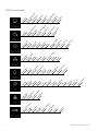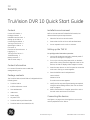
1
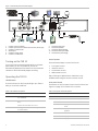
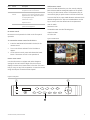
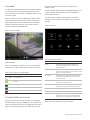
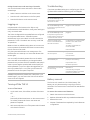
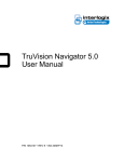
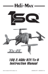
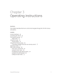
GE
Security
TruVision DVR 10 Quick Start Guide
Content
Installation environment
Contact information 1
Package contents 1
Installation environment 1
Setting up the TVR 10 1
Connecting the devices 1
Turning on the TVR 10 2
Operating the TVR 10 2
Live mode 4
Overview of the main menu 4
Logging on 5
Turning off the TVR 10 5
Troubleshooting 5
Battery removal 5
TVR 10 screen map 6
Refer to the user manual for detailed information, but
observe these important requirements:
•
Place the TVR 10 in a secure location.
•
Ensure that the TVR 10 is in a well-ventilated area.
•
Do not expose the unit to rain or moisture.
Setting up the TVR 10
To quickly put the TVR 10 into operation:
1.
Connect all the devices required to the back panel of
the TVR 10. See Figure 1 on page 2.
2.
Turn on the unit using the power switch on the back
panel. After running automatic diagnostic tests on the
devices, the TVR 10 displays video images on-screen.
3.
Press the Menu button on the front panel to access the
main menu. The log on screen appears.
4.
Enter the default user ID and password.
Contact information
For contact information see our Web site:
www.gesecurity.com.
Package contents
User ID: admin
Password: 1234
The TruVision DVR 10 (model TVR 10) is shipped with the
following items:
•
TruVision DVR 10
•
IR (infrared) remote control
•
Two AAA batteries
•
USB mouse
•
Power supply
•
AC power cord
•
TruVision DVR 10 Quick Start Guide
•
TruVision DVR 10 User Manual (on CD)
The main menu screen appears.
5.
Modify the TVR 10 preconfigured settings as required,
using the various dialog screens. (See “TVR 10 screen
map” on page 6.)
6.
When customization is complete, press ESC to exit to
the main menu and return to live mode.
Connecting the devices
Use Figure 1 on page 2 as a visual guide to connect the
various peripherals to the TVR 10.
© 2009 GE Security, Inc.
P/N 1068259 • REV A • ISS 06JUL09
Figure 1: TVR 10 back panel connection diagram
RS-485
OUT 1 G
T+ T- R+R-
1
POWER
VGA
1 3
2 4
2
VIN
VOUT
AIN
AOUT
ETHERNET
ALARM IN 1 2 3 4 G G
+12V
L ni k/ A ct
1 00
P ow e r
F D / C ol
1
1.
2.
3.
4.
5.
6.
2
3
4
5
6
7
8
Connect up to four cameras
Connect up to two CCTV monitors (one for main, two for spot)
Connect to a VGA monitor
Alarm output
Connect to a PTZ control
Connect to a USB mouse
Turning on the TVR 10
Turn on the TVR 10 using the power switch on the back
panel. When you turn on the device, the TVR 10
automatically displays all live views from the connected
cameras. It also automatically begins recording.
Operating the TVR 10
LED indicators
The LED indicators on the front panel light up or flash to
alert you to various conditions.
7.
8.
9.
10.
11.
Connect to audio input
Connect to speakers
Connect to network devices
Connect to alarm input cables
Connect to the power supply
Control options
There are several ways to control the TVR 10:
•
•
•
•
Front panel control
IR remote control
Mouse menu control
Web browser control
Tip: A full range of alphanumeric characters is only
available when using the mouse or remote control.
Front panel control
The buttons on the front panel control most functions. See
Figure 3 on page 3 for locations of the controls.
Table 1: LED indicator descriptions
Table 2: Front panel control descriptions
LED
Description
Item
Control
Description
Power
Steady green: The TVR 10 is powered up with no
error conditions.
1
Status LEDs
Show the TVR 10 status. See Table 1 above.
2
Numeric buttons
Switch camera views and input numbers.
HDD
Blinking red: Video is being recorded onto the hard
drive.
MENU
Accesses the main menu.
Solid red: The hard drive has an error.
DISP
Displays multiscreen live mode. Accesses live
mode.
Blinking green: Network data is being transferred to
or from the TVR 10.
SRCH
Displays the Play Back screen for video
playback.
PTZ
Accesses the PTZ control mode.
LIVE
Displays Camera 1 in live mode.
REC
Displays the Manual Record screen.
Tx/Rx
2
TruVision DVR 10 Quick Start Guide
Item
Control
Description
Web browser control
2
ESC
Cancels the current changes and returns to
the previous screen or main menu.
3
Directional
controls
In menu mode, Left or Right Arrow buttons
select and Up or Down Arrow buttons edit. In
playback mode, Left or Right Arrow buttons
control playback speed.
The TVR 10 Web browser lets you view, record, and play
back videos as well as manage all aspects of the system
from any PC with Internet access. The browser’s easy-touse controls give you quick access to all TVR 10 functions.
Playback control.
To access the TVR 10, open a Web browser and enter the IP
address assigned to the TVR 10 as a Web address. On the
log on screen, enter the default user ID and password.
Confirms the selection. Enables or disables
options. Pauses playback.
User ID: admin
Password: 1234
PTZ direction control.
ENTER
The Web browser uses the following ports.
IR remote control
Video Port: 8000
HTTP Port: 80
IR remote control operation is similar to the front panel
operation.
Figure 2: Web browser
To connect the remote control to the TVR 10:
1.
Insert the AAA batteries (included in the box) in the
remote control.
2.
Turn on the TVR 10 and wait for the live video to
appear.
3.
On the remote control, press and release the Power
button. The remote control is now operational.
Mouse menu control
Use the USB mouse to navigate and make changes to
settings in the user interface. Right-click the mouse to
display a mouse control menu when in live view. This menu
lets you carry out any TVR 10 operation. Connect the mouse
using the USB port located at the back panel.
Figure 3: Front panel
1
Power
HDD
Tx/Rx
3
TVR10
e
1
Disp
2
Srch
3
PTZ
4
Live
MENU
Rec
Esc
2
TruVision DVR 10 Quick Start Guide
3
Live mode
The TVR 10 automatically enters live mode when powered
on. Live mode is the normal operating mode of the unit.
From live mode, you can switch to playback mode or enter
the menu system.
While in live mode, the TVR 10 displays the status of each
video channel at the bottom of the screen. See Figure 4
below. Right-click the mouse, and then click Show/Hide
Status (or press the # button on the remote control) to
activate or deactivate the status bar.
also press the MENU button on the front panel or the
remote control.
Access to different dialog screens varies depending on your
access privileges. Most screens will only be available to
system administrators.
The main menu has eight commands. Each command
displays a screen that lets you modify a group of TVR 10
settings.
Figure 5: Main menu
Figure 4: Live mode example
Table 4: Main menu descriptions
Camera status
Command
Function
Display
Configures the login password request, menu
timeout, video standard, time and date, and
multiscreen layout.
Camera
Configures the camera names, video adjustment,
advanced camera settings, time and date on-screen
position, and motion detection.
Recording
Configures the recording mode, image resolution,
recording rates, bit rates, and pre- or post-event
recording settings.
Each icon represents a camera. The icon color shows the
camera status. Table 3 below gives the status color code.
Table 3: Camera status icon color descriptions
Icon
Color
Status description
White
No video signal
Yellow
Standby recording (when recording upon alarm and/or
motion)
Network
Configures the standard network settings, e-mail,
and advanced network settings.
Green
Recording
Alarms
Blue
Motion detection
Configures the alarm input type, alarm rules, alarm
output type, PTZ linkage, and notification settings.
PTZ
Configures PTZ protocols and PTZ addresses.
Red
Alarm
User
Configures users, passwords, and access rights.
Utilities
Configures the firmware upgrade, hard drive
settings. Lets you view logs, acknowledge alarms,
restore to factory settings, reboot, and power off.
Overview of the main menu
The main menu lets you set up the TVR 10 or change the
default settings to suit your installation. You must be in live
mode to access the main menu. To display the main menu,
right-click the mouse, and then click Main Menu You can
4
Refer to the user manual for more information.
TruVision DVR 10 Quick Start Guide
Exiting the main menu and returning to live mode
Troubleshooting
You can exit the main menu and return to live mode in
several ways:
If you have a problem setting up or configuring your TVR 10
try these solutions before contacting your local supplier.
•
Select Camera or Multiview on the mouse menu.
•
Press the LIVE or ESC buttons on the front panel.
•
Press the ESC button on the remote control.
Logging on
Use passwords to limit access to the TVR 10. Only
authorized users should be able to modify menu settings or
carry out certain tasks.
The TVR 10 is shipped with one predefined user configured
as the system administrator. The default system
administrator log on uses “admin” as a user name with a
password of “1234.” The admin user can carry out all TVR
10 operations.
Failure
Possible reasons
After plugging in and turning on
the unit, the POWER light on the
front panel does not turn on, and
the fan does not work.
Power supply is not functioning.
Fan is not functioning or is not
After plugging in and turning on
plugged in to the main board.
the unit, the POWER light on the
front panel turns green but the fan
does not work.
After plugging in and turning on
the unit, the POWER light on the
front panel turns green and the
indicator lights on the panel turn
on, but the fan does not work.
The ATX plug in main board is not
plugged in.
There are no images in the
monitor connected with VOUT
after TVR 10 is started.
If a VGA monitor is connected it takes
precedence over a BNC monitor
connection.
Note: You hear an audible warning when an incorrect user
name or password is entered. After three incorrect entries,
the unit returns to live mode.
The cable connected with the
monitor has failed.
Main board failure.
Only the system administrator can manage users. The
administrator can create up to 15 users and allocate their
access rights.
Cannot find the hard drive during
the reboot process.
You can modify the admin password but not the admin
user name. We recommend that you change the admin
password once you have finish the installation and setup in
order to protect against unauthorized access. Specify an
admin password of up to four digits. We suggest that you
use only numbers from 1 to 4 so that you can enter the
password from the front panel if required.
TVR 10 cannot control PTZ through RS-485/422 cable is not connected
the RS-485/422 port.
properly or not functioning.
Caution: Keep the admin password in a safe place. If you
should forget it, you must return the TVR 10 to the service
center to be reconfigured.
The power cable of the hard drive is
not connected.
Hard drive failure.
PTZ parameters error.
RS-485/422 port failure.
Client software cannot view the
TVR 10 live image.
Network error.
Connected using wrong DVR
parameters (IP address, port number,
username or password, etc).
Battery removal
To turn off the TVR 10:
The TVR 10 unit contains one 3V Lithium battery. This
battery can only be removed by a recycling or service
technician. The remote control comes with two AAA alkaline
batteries.
1.
To remove the remote control batteries:
Turning off the TVR 10
On the main menu, click Utilities, and then click Power
Off.
— or —
Press and hold the Power button on the remote control
for at least five seconds. Enter a user name and
password if required.
2.
Wait 10 seconds then turn off the power switch located
on the back of the unit.
TruVision DVR 10 Quick Start Guide
1.
Detach the remote control’s back cover.
2.
Replace the batteries with any standard AAA batteries.
3.
Reattach the cover.
4.
Dispose of the batteries as required by local ordinances
or regulations.
5
6
ar
d
w
ff
ul
t
up
g
e
io
n
ra
d
rm
at
pu
t
fo
de
fa
e
er
o
ot
or
y
eb
o
ct
Po
R
Fa
ar
sk
ou
t
di
m
Fi
rm
w
H
in
lo
g
em
w
Al
ar
Vi
e
Sy
st
d/
ify
ge
s
ri v
ile
ge
ile
ul
tp
tp
riv
ef
a
e
d/
Ve
r
et
or
D
el
ss
w
Se
D
Pa
Ad
s
at
co
n
C
op
to
ca
m
er
ur
r
to
to
u
ow
y
Sh
ad
Pr
es
et
Pr
es
et
l
es
s
tro
ad
dr
to
co
l
PT
Z
Pr
o
Fl
ow
Pa
rit
ts
bi
ts
bi
y
a
St
op
D
te
a
ra
am
er
Ba
ud
C
a
op
y
N
C
ot
y
n
e
m
tim
al
ar
at
io
to
ifi
c
op
ou
t
t
m
ou
t
in
/P
TZ
al
ar
es
ou
to
ru
l
io
n
m
ra
t
Al
ar
Du
Al
ar
m
C
pu
t
pe
in
ty
rm
pu
t
Al
a
In
Al
ar
m
D
D
N
S
PP
Po
E
k
se
t
as
ce
d
t
ay
m
es
s
po
r
an
ttp
t
ew
Ad
v
H
Po
r
G
at
ne
t
ad
dr
Su
b
IP
tin
gs
es
e
e
C
op
y
to
tt
ul
e
a
e
er
tim
im
e
ca
m
nt
en
ve
ev
st
-e
Pr
e-
te
sc
he
d
ra
or
d
ra
t
Po
ty
pe
od
e
ol
ut
io
n
R
ec
Bi
t
m
a
am
Fr
am
R
St
re
er
or
d
C
am
R
ec
ot
io
e
C
op
y
to
ti n
er
a
se
t
ca
m
di
gs
sp
la
si
ti o
n
io
n
te
po
ct
da
o
le
de
te
d
ce
d
n
an
Ad
va
n
M
Ti
m
tit
id
e
a
a
us
tv
am
er
am
er
Ad
j
C
C
y
re
n
e
ul
ti sc
re
en
ti m
ns
pa
d
tr a
cy
or
d
rd
sc
al
er
an
u
e
en
at
M
D
M
da
t
sw
eo
u
st
an
tim
le
eo
u
En
ab
Vi
d
en
pa
s
ID
ui
re
ic
e
eq
ev
M
R
D
TVR 10 screen map
TruVision DVR 10 Quick Start Guide