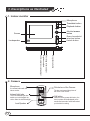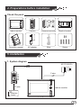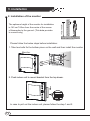
1
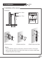
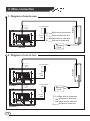
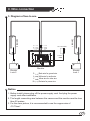
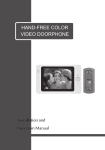
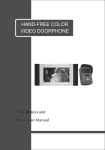
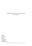
HAND-FREE COLOR
VIDEO DOORPHONE
Installation and
Operation Manual
TABLE OF CONTENTS
1. Brief introduction
1
2. Functions
2
3. Descriptions as illustrated
3
4. Preparations before installation
4
5. Installation
4
6. Wire connection
7
7. Operation
10
8. Note
12
9. Trouble shooting
13
10. Specifications
13
1. Brief introduction
Thanks for using our products, the four wire system video
doorphone is a luxury used to unitary flat for safety. It used advanced
technology and newest chipset, which improves the stability of the
system and far distance. The system has the function such as:
visible phone, hand-free surveillance, unlock, capture pictures of
visitors, infrared vigil, every household intercom function, auto turn off,
and so on. The system has multi tie-in function such as one camera to
one monitor, one to two, two to one, two to two and one to three.
Which satisfied by customer,s require for different villa.
The products is faddish, goodliness, generous, thinner and
hanging on the wall, portable, take less place, which as a adornment.
The function is dependable and easy to use, it is the perfect family
burglarproof facility and widely used in unitary flat, villa, office and
public building, which is the best present for your friend.
For the sake of your safety, please use series burglarproof facility!
It will make your life safe and easy!
1
2. Functions
Powerful function
Support picture capture function, can store 20 pictures and automatic
overwrite, auto turning off to save power.
Security
Unlock: to avoid miss press on "unlock" button, unlock function is only
operated while monitor is turned on, that ensure the safety of your house.
High solution picture
Using the high resolution camera and 7 inch TFT LCD color digital screen.
The resolution is 800ˇRGBˇ480. The picture is clear, nice, colorful and
steady.
Multi Connection
The system can be installed in multi tie-in manners as one camera to one
monitor, one to two, two to one, two to two and one to three. It can satisfy
the kinds of villa.
Conveniency in installation
It is very simple to install, easily using and maintain.
2
3. Descriptions as illustrated
1. Indoor-monitor
Microphone
Time/date button
Playback button
Monitor/answer
button
Screen
Every household
intercom button
Unlock button
Loudspeaker
Ring choose button
Chord ring volume adjust
Brightness adjust
Communication volume adjust
2. Camera
Microphone
for communication with the
indoor monitor
Pinhole lens of the Camera
The lens can transmit the picture of
the visitor to the monitor
Infrared light tube
The in-set Infrared light tube
enable you to distinguish the
visitor under the insufficientlight
Loud Speaker
3
Call button
When the visitor presses this button, the
visitor's picture will be displayed on the
monitor and a sound of music will remind
you the visitor's coming.
4. Preparations before installation
Check the pack
Indoor monitor
Camera
Camera accessory
Monitor bracket
AC adapter
Wire
Screw
R
LO
E
ON
E CO
-FREORPH
ND
HA O DO
VIDE
and
lation nual
Instal n Ma
tio
Opera
Operation manual
5. Installation
1. System diagram
AC:110-240V~
4 wire
2 wire
Camera
2 wire
Indoor monitor
Electric
Lock
4
5. Installation
The optimum height of the monitor for installation
is 145 cmˇ160cm from the centre of the screen
of themonitor to the ground. (This data provides
to consult only)
145cmˇ160CM
2. Installation of the monitor
Please follow the below steps before installation:
1. Take two bolts fix the bottom piece on the wall and then install the monitor
M o n it o r
Wall
2. Push indoor unit to mount bracket from the top dowm.
In case to pull out the indoor unit, please follow the step 1 and 2.
5
5. Installation
3. Installation of the camera
Positioning
about 180cm
about 110cm
53ˇ
50cm
66ˇ
about 80cm
50cm
l
Wal
l
Wal
(1)Flush mount type
l
Wal
(2)Surface mount type
(3)Bevel-surface mount type
Notice:
Do not install the camera on the places under the sunshine. If the street
light or other light reflect at the back of the visitor, you need to install lamps
to make the picture more clearer.
6
6. Wire connection
1. Diagram of one to one
Black
White
Yellow
Red
AC:110-240V~
+13.5V
GND
G
A
V
B+
Black wire for ground wire
Camera
B+ V A G
White wire for audio wire
Yellow wire for video wire
Red wire for power wire
Electric
Lock
Monitor
2. Diagram of one to two
B+ V A G
Black
White
Yellow
Red
AC:110-240V~
Camera
+13.5V
GND
B+ V A G
Black
White
Yellow
Red
Monitor 1
AC:110-240V~
Electric
Lock
+13.5V
GND
Monitor 2
7
G
A
V
B+
Black wire for ground wire
White wire for audio wire
Yellow wire for video wire
Red wire for power wire
6. Wire connection
3. Diagram of two to one
Camera 1
AC:110-240V~
Black
White
Yellow
Red
Black
White
Yellow
B+ V A G
Red
Camera 2
B+ V A G
+13.5V
GND
Monitor
Electric
Lock 2
G
A
V
B+
Black wire for ground wire
Electric
Lock 1
White wire for audio wire
Yellow wire for video wire
Red wire for power wire
Notice
1. Before install, please plug off the power supply cord. And plug the power
supply cord after installation.
2. The length connecting wire between the camera and the monitor must be less
than 50 metres.
3. For the clear picture, it is recommended to use the copper wire of
4ˇ0.75mm2.
8
6. Wire connection
4. Diagram of two to two
Camera 1
AC:110-240V~
Black
White
Yellow
Red
Black
White
Yellow
B+ V A G
Red
Camera 2
B+ V A G
+13.5V
GND
Monitor 1
Red
AC:110-240V~
Black
White
Yellow
B+ V A G
Black
White
Yellow
B+ V A G
Red
Electric
Lock 2
+13.5V
GND
Monitor 2
G
A
V
B+
9
Black wire for ground wire
White wire for audio wire
Yellow wire for video wire
Red wire for power wire
Electric
Lock 1
7. Operation
ˇ Calling by the visitorŁ
While the visitor press the CALL button, the Ding Dong sound will be heared from the indoor monitor,
and the picture of the visitor is display on the monitor screen.
When seeing the picture of the visitor, press the MONITOR/ANSWER button to communicate with the
visitor, and press the UNLOCK button to open the door and let the visitor come in. After communicate,
press MONITOR/ANSWER button again to finish the call the screen will also turn off.
If the holding time over 60 seconds, the extension monitor will automatic turn off .
ˇ Stakeout:
While Standby state, press the MONITOR/ANSWER button then will display the outdoor picture on the
monitor.
ˇ Intercom function: (only available when more than 2monitors)
When power on and standby, click INTERCOM button to ring other indoor monitors, thereafter, other
monitors can answer by click MONITOR/ANSWER button, click again to hangup.
Remarks: if any of the monitor need do MONITOR, please hangup the intercom first, or you have to
wait 60seconds till the intercom is off
ˇ Chord ring setting:
Press the RING button to enter the ring setting and then press one more time to change the ring, there
are total 9options, click MONITOR/ANSWER button to confirm the existing ring-tone.
ˇ Language Setting:
aa When power on and standby, click MONITOR/ANSWER, then TIME/DATE button to enter MENU, clic
a TIME/DATE button again to swift different languag
ˇ Date and Time setting:
a When power on and standby, click MONITOR/ANSWER button, and TIMING/DATE button to
nter a MENU, then PLAYBACK button will be used for CONFIRM, TIMING/DATE will be turning up bu
ton, RING will be turning down button setting up date from YEAR to MONTH to DAY, after all done, click
MONITOR/ANSWER button to SAVE and EXIT.
ˇ Playback:
When standby, click MONITOR/ANSWER button, then PLAYBACK button to play back the last picture,
click TIMING/DATE button to review the next picture, MONITOR/ANSWER button to exit, or it will be
exit automatic in 60seconds.
ˇ Photo delete:
When standby, Click MONITOR/ANSWER button, then TIMING/DATE button to enter MENU,
PLAYBACK button will be used for CONFIRM, choose DELETE ALL and click TIMING/DATE button
to delete all pictures.
ˇ AUTO recover:
When there are 20pitures recorded, the system will AUTO recover the earliest picture to be the lastest
one.
ˇ Others operation:
If you think the monitor volume is not applicable or the picture shown on the screen is too light or too
dark, you can adjust the Volume and Brightness knob to reach pleased effect of volume and picture.
10
7. Operation
˘
Press the Call button by
the visitor.
The picture of the visitor
is displayed on the
monitor screen.
Who is it?
It is me!
11
Press the Monitor/answer
button and communicate
with the visitor.
Press the Unlock button
to open the door.
On standby, press the
Monitor/answer button
then the outside picture
is in stakeout.
Press the Monitor/answer
button and then press the
look back button, then you
can see the visitors' photos .
8. Note
As illustrated
Do not put the doorphoe near
the strong magnetic places.
Do not spray water
or liquid to the video
doorphone directly.
Do not shock the video
doorphone
1
2
3
Do not expose video phone to the
sunshine or strong reflection ray.
Plug off the power
cord while not use
for a long time.
4
5
Do not insert plugs into
a socket to be filled.
(This will be caused a
fire or short circuit)
Do not installed the doorphone
near any ammonia or poisonous
gas.
6
7
Do not try to dismantle the
doorphone, as the high voltage
is inside it.
8
ent
terg
De
Do not wipe the machine
with detergent or other
chemic impregnant.
Do not try to dismantle the
machine while failure to
function. Please contact with
the local service.
9
10
12
9. Trouble shooting
1. No sound while calling
a. The connection cable between monitor and camera is loose.
b. The volume has be turn to the end.
2. Unclear image
Please check if the brightness is turned to too down, please adjust the
brightness knob.
3. Can't unlock
Unlock cable is not well connected, or shortcut. Or, the connection cable
is too far away or too slim from the indoor and outdoor unit, please try to
change to better quality cable. Otherwise, please check if the electric lock
is compatible with this product.
4. Date/time are inaccurate
When the power dropped or draw out, insert the power again, the date and
time will be inaccurate, only need to reset it.
10. Specifications
Indoor-monitor
Power Supply
Power Consumption
Screen
Resolution
Video Input
Cutoff-Time
Mike Sensitivity
Operation Temperature
Call Tone
External Dimension
13
DC13.5V
Standby: Ł1.5W; Working:Ł8W
7" TFT color digital screen
٨٠٠ˇRGBˇ٤٨٠
١Vp_p
Stakeout: 1 minute; Conversation: 1 minute
-٣٦ˇB ٢d
-١٥ˇˇ+٥٠ˇ
chord ring
237ˇ158ˇ28(mm)
Outdoor-camera
Power Supply
Power Consumption
Imagery Angle
Lamp-house at Night
Operation Temperature
External Dimension
DC 12V(supplied by the monitor)
Working: Ł2W
Diagonal: about 53ˇ
Infrared LED
-١٥ˇˇ+٥٠ˇ
160ˇ70ˇ26 (mm)
Warning:
To prevent injury, this apparatus must be securely attached to the
floor/wall in accordance with the installation instructions.
The mains plug is used as the disconnect device, the disconnect
device shall remain readily operable, and it shall be disconnected
from the mains completely.
ˇ The plug is used as disconnect device form the mains supply, the
plug shall remain readily operable.
ˇ The apparatus should not be exposed to dripping or splashing and
that no objects filled with liquids, such as vases, shall be placed on
the apparatus.
ˇ No naked flame sources, such as lighted candles, should be placed
on the apparatus.
Notice:
ˇ Due to continuing improvements, the features and design are
subject to change without notice.
ˇ This manual is only intended for reference. No further notice is
available to any modification of all information contained therein.
ˇ For the imprecision, mistake or misprint in the manual, will be
explained by the producer only.
14
Door Guard
e
ected by true
onn
c
fee
e
r
l in
a
Baby Room
g
!
W
Warehouse
Gate Switch
Visitor Door
Night Vision
Inter-com
Office