1
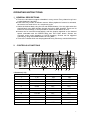
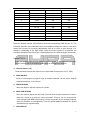
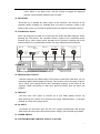
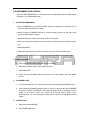
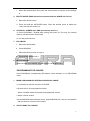
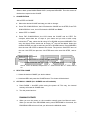
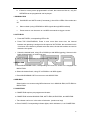
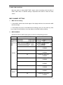
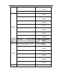
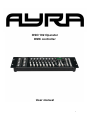
OSO 192 Operator
DMX controller
User manual
1
Introduction:
Thank you for purchasing this Ayra DMX Controller. To enjoy the full advantages of our
products and for your own safety, please read this user manual carefully before you use
this unit.
FEATURES:
* 192 DMX Channels.
* 30 Banks each composed of 8 programmable scenes.
* 8 Fades adjusting output level.
* Built-in Microphone.
* AUTO mode is controlled by TAP SYNC button and SPEED fader
* MIDI control through MIDI interface.
* 4 digits LED display.
* Blackout master controlled by Manual or Remote.
* CHASE programming and CHASE running, manual control and remote control.
* Fade Time control.
* DMX polarity selects.
* FOG Machine control.
Box contents:
1 DMX Console
1 AC/DC adaptor
1 User Manual
2
OPERATING INSTRUCTIONS:
1.GENERAL DESCRIPTIONS:
a. There are 192 channel outputs selectable in every scene. Every channel may have
a value between 0 and 255.
b. Each bank may contain 8 different scenes. When playback of scenes is activated,
the scenes in a bank will run in a continuous cycle.
c. Select the desired bank using the UP and DOWN buttons. You may also select the
desired bank using MIDI signals through the built-in MIDI interface There are 30
banks for scene storage, it is not possible to select several banks at once.
d. Scenes can be executed automatically, and the duration depends on the desired
speed, selectable with the SPEED fader and TAP SYNC button. Scenes are
executed under music triggering or NOTE triggering. Scenes can be triggered
manually by using the SCENE buttons in every bank.
e. There are 6 chases which can be programmed freely. Each may contain 240 scenes.
2.
CONTROLS & FUNCTIONS
1.Scanners(1-12)
Scanners
Channel
Fade control
1
1-16
2
17-32
OFF
OFF
3
33-48
OFF
OFF
4
49-64
OFF
OFF
5
65-80
OFF
OFF
6
81-96
OFF
OFF
7
97-112
OFF
OFF
8
113-128
OFF
OFF
9
129-144
OFF
OFF
10
145-160
OFF
OFF
11
10-176
OFF
OFF
12
177-192
OFF
OFF
OFF
LED
OFF
3
Scanners
Channel
Fade control
LED
1
1-16
ON
ON
2
17-32
ON
ON
3
33-48
ON
ON
4
49-64
ON
ON
5
65-80
ON
ON
6
81-96
ON
ON
7
97-112
ON
ON
8
113-128
ON
ON
9
129-144
ON
ON
10
145-160
ON
ON
11
10-176
ON
ON
12
177-192
ON
ON
Press the desired scanner (fixture button), and the corresponding LED will turn on. The
individual channels of the selected fixture are enabled to change the values, even when
scenes are running, for on-the-fly adjustments such as a colour or gobo change, or a
change in positioning of the light output. When the fixture button is de-selected, the
individual channels of the fixture can not be adjusted and no visible changes will be seen.
2. Scene button
Press one scene button to run a scene (or to store scene in the programming mode),
and the second digit of the display shows which of the scenes is selected.
3. Channel faders (1-8)
Slide the fades to adjust the output level of each DMX channel from 0 to FF (255).
4. PAGE SELECT
Press to select page A to page B. Page A contains channels 1-8 of a fixture, Page B
contains channels 9-16 of a fixture.
5. SPEED SLIDER
Move the slider to adjust the speed of a chase.
6. FADE TIME SLIDER
Move the slider to adjust the fade time. The fade time controls the amount of time it
takes for a scene to go from one value to another. This way you can control fluent
color changes (with RGB LED fixtures) or fluent movement of your intelligent lighting
(such as scanners or movingheads). Find the optimal balance between the speed
and fade time by experimenting.
7. LED DISPLAY
4
8. BANK button (↑or↓)
Press UP or DOWN to scroll trough the different banks, the third and fourth digit of the
display shows which bank is currently activated.
9. CHASE 1-CHASE 6
Select the desired chase to activate a program (built from scenes in a continuous
loop), or edit the contents of the chase by selecting scenes you want to combine in a
chase..
10. PROGRAM
When the controller is in the manual mode, press PROGRAM for 2 seconds. You will
see that the corresponding LED blinks. In program mode, it is possible to adjust
scenes and chases. Press PROGRAM once more to return back to the manual mode,
the corresponding LED turns off.
11. MIDI/ADD
a、 Press the MIDI button when the controller is activated. The third and fourth digit
of the display will flash. Select the MIDI channel using the UP and DOWN
buttons, press the MIDI button once more or any other key excluding UP or
DOWN to end the MIDI channel settings.
b、 Press this key to make scenes or chases when in PROGRAM mode.
12. AUTO/DEL
a、 When in the RUN mode, press Auto/Del to activate the automatic chase run
sequence. The corresponding LED will turn on. Press the button once more to
exit the automatic mode, the corresponding LED will turn off.
b、 Press this button to delete scenes and chases when in PROGRAM mode.
13. MUSIC/BANK COPY
a、 When in the RUN mode, press this button to activate the MUSIC mode. The
corresponding LED will turn on. Press the button once more to exit the MUSIC
mode, the corresponding LED will turn off.
b、 Press this key to copy banks when in PROGRAM mode.
14. TAP SYNC/DISPLAY
a、 When in AUTO RUN mode, use the TAP SYNC function to determine the
amount of time between two steps. This way it is possible to tap the button on
the beat of the music, for music-synchronised shows. The maximum amount
of time between two steps is 10 minutes.
b、 When in PROGRAM mode, use the button to switch between Step and Bank
5
mode. When in any other mode, use this function to toggle the displayed
channel-values between 000-225 and 0%-100%.
15. BLACKOUT
Press this key to disable all visible output of the channels. The functions of the
controller remain available, for example when you want to change a chase in the
climax of the music, or to activate a special function to release at a specific moment.
16. FOG Machine button
Some fog machines are able to be used with the AYRA 192 DMX Operator. When
pressing the FOG button, the controller sends a signal to the connected smoke
machine and a 100% output will be activated on the machine. Working with every
smoke machine is not guaranteed as there are many different brands and types.
MIDI IN
DMX POLARITY
SELECT
DMX OUT
2
1=Ground
2=Data 3=DATA+
+
POWER
SWITCH
FOR FOG CONTROL
OUTPUT ONLY
1
1=Ground
2=Data +
3=DATA3
17
DC INPUT
-
18
19
+9V~12V,300mA min.
20
21
22
17. MIDI IN
Use this 5-pin DIN connector to receive MIDI data from a MIDI-device, such as a
button trigger, keyboard or footcontroller.
18. DMX POLARITY SELECT
Select the polarity of the DMX output. This function needs to be used when you use
old Martin lighting effects (Martin Protocol). The function inverts the signal of pins 2
and 3. When your lighting fixtures don’t correspond properly to the values of the
controller, switch the polarity to make sure that this function does not cause the
problem.
19. DMX OUT
Use this 3-pin XLR output to connect all of your DMX lighting fixtures. By
daisy-chaining the fixtures and selecting the proper DMX-adresses, it becomes
possible to control every single fixture.
20. DC INPUT
Connection for the power input: DC 9V~12V. A power transformator with at least
300mA must be used, when the included power supply is lost or broken by accident.
21. POWER SWITCH
22. FOR FOG MACHINE CONTROL OUTPUT (5-pin DIN)
6
PROGRAMMING FOR SCENES:
Press the PROGRAM button for 3 seconds, the corresponding LED will blink, which
indicates it is in PROGRAM mode.
1. SECNE PROGRAMMING
a. Press SCANNER key to select the DMX channel composed of 8 channels (or 16
when the Page A/B function is used).
b. Select multiple SCANNER fixtures to control multiple fixtures at the same time
(synchronized channel values).
c. Adjust the faders to select the several values of channels.
d. Select and adjust the output level of every channel continuously until all devices are
set.
e. Press MIDI/ADD.
f. Select the desired bank to save your scene using the UP and DOWN keys.
g. Press one of the 8 SCENE buttons (1-8) to store this SCENE at a specific place.
2. SCENE EDITING
a. Select the desired scene, stored in one of the banks.
b. Adjust the channel values of the selected scene.
c. Press MIDI/ADD
d. Press the same SCENE button as selected in the first step to store the edited
scene.
3. SCANNER COPY
a. If a scanner (fixture) is set, press and hold the corresponding SCANNER button.
b. Press another SCANNER button to copy to, then the values of the first SCANNER
is copied to anther SCANNER. This makes programming for intelligent fixtures
easier as the same values are copied to a second fixture (gobo, color,
strobe/dimmer, etc.) Just change the pan and tilt values to make programming
easier.
4. SCENE COPY
a. Select the desired SCENE.
b. Press MIDE/ADD once.
7
c. Select the desired bank, then press the scene button to copy the scene-settings
to.
5. DELETE SCENE (DMX channel incorporated with this SCENE are set to 0)
a. Select the desired scene.
b. Press and hold the AUTO/DEL button. Press the desired scene to delete the
scene and set the values to 0.
6. CLEAR ALL SCENES (ALL DMX channels are set to 0.)
a. Press PROGRAM + DOWN while turning the power off. This way, the internal
memory will delete all the stored data.
b. Turn the power back on.
7. COPY BANK
a. Select the desired bank
b. Press MIDI/ADD.
c. Select the bank you wish to copy to.
d. Press MUSIC /BANK COPY
8. DELETE A BANK
Select the bank to be deleted, press Auto/DEL+ Music/Bank copy.
PROGRAMMING FOR CHASES:
Press PROGRAM, corresponding LED flashes, which indicates it is in PROGRAM
mode.
1.
MAKE A PROGRAM OF SEVERAL SCENES IN A CHASE.
a. It is possible to add 240 scenes to a CHASE.
b. Scenes will run in the programmed order.
Select a CHASE which will contain the programmed scenes.
c. Select a scene of bank.
d. Press MIDI/ADD. Select another scene, press MIDI/ADD. Etc. until you are satisfied
with the amount of scenes in this chase
2.
COPY A BANK TO A CHASE
8
Select a bank, press MUSIC/BANK COPY, and press MIDI/ADD. Then the scenes of
the bank are copied to the CHASE.
3.
CHASE EDITING
Add a STEP IN CHASE.
a、 Select the desired CHASE and step you wish to change.
b、 Press TAP SYNC/DISPLAY, the LCD shows the CHASE and its STEP, Press TAP
SYNC/DISPLAY once, the LCD shows the SCENE and BANK.
c、 Add a STEP in CHASE.
d、 Press TAP SYNC/DISPLAY, the LCD shows the CHASE and its STEP. For
example, when there are 15 steps in your chase and you wish to add a step
behind the 9th step, select the 9th using UP or DOWN and press MIDI/ADD. This
way, the chase will be saved and an empty 10th step will be added. Select the
desired SCENE you wish to add using the UP or DOWN buttons, Press MIDI/REC,
then the new 10th STEP is added to the chase. The previous 10th STEP turns to
the new 11th STEP, the previous 11th STEP turns to the new 12th STEP , and so
on.
e、 Delete a STEP in CHASE
Select the desired STEP in a chase and then press AUTO/DEL.
For example, select the 10th STEP using UP or DOWN, press AUTO/DEL, then
the 10th STEP is deleted, the previous 11th STEP turns to the 10th STEP, and so
on.
4.
DELETE A CHASE
a. Select the desired CHASE you wish to delete.
b. Hold Auto/DEL and press the CHASE button. The chase will be deleted..
5.
CLEAN ALL CHASE (ALL SCENES are still available)
a. Press DOWN + Auto/DEL while turning the power off. This way, the internal
memory will erase all CHASE data.
b. Turn the power back on.
RUNNING SCENES
a. When you turn the power on, the controller normally goes into Manual mode..
When you are still in the PROGRAM mode, press PROGRAM for 2 seconds, the
PROGRAM LED will turn off and you will enter the MANUAL mode.
9
b. If there is not any scene programmed in a bank, the scene can’t be run, only the
SCENES that are programmed can be played..
1. MANUAL RUN
a. Quit MUSIC and AUTO mode (if necessary), check if the LEDs of the modes are
off..
b.
Select a bank (using UP/DOWN or MIDI signals through MIDI interface)
c.
Press scene to run the scene or use MIDI commands to trigger a scene.
2. AUTO RUN
a. Press AUTO/DEL, corresponding LED is ON.
b. Press TAP SYNC/DISPLAY, Press it once more after some time, the interval
between two pressing is assigned to the speed of AUTO RUN, the maximum limit is
10 minutes. If the button is pressed more than twice, the last two strokes are used to
determine the speed.
c. Select the desired bank, using UP or DOWN (or with MIDI triggering). Scenes in this
bank will be played in a continuous loop.
d. Press Auto/DEL once more to exit the AUTO RUN mode.
3. MUSIC RUN
a. Press MUSIC/BANK COPY, corresponding LED turns on, scene run is engaged into
MUSIC RUN.
b. Select the desired bank, using UP or DOWN or via MIDI signals.
c. Press MUSIC/BANK COPY once more to exit MUSIC RUN.
4. MIDI RUN
Select bank to run scenes using MIDI whenever it is in MANUAL RUN, AUTO RUN or
MUSIC RUN.
5. CHASE RUN
a. CHASE RUN requires pre-programmed chases..
b. CHASE RUN includes MANUAL RUN, AUTO RUN, AUDIO RUN, and MIDI RUN.
c. Two chases can be run in the order of selection. (continuous loop)
d. Press CHASE, Corresponding indicator lights, which indicates it, is in CHASE RUN.
10
6. FADE TIME CONTROL
Move the slider to adjust FADE TIME. Output varies accordingly and the effect of
FADE TIME relies on SPEED settings. Experiment with both to create the best
values.
MIDI CHANNEL SETTING:
1.
MIDI channel setting
a. Press MIDI, the third and fourth digits of the display will blink, this selects the MIDI
channel settings.
b. Press MIDI once more to end MIDI channel settings. Also you can press any other
key except UP and DOWN or move the faders to end MIDI channel setting.
2.
MIDI RUNNING
NOTE ON: Receive NOTE ON signals to execute corresponding function.
BANK
NOTE NUMBER
FUNCTION
00
TURN ON TURN OFF
SCENE1
01
TURN ON TURN OFF
SCENE2
02
TURN ON TURN OFF
SCENE3
03
TURN ON TURN OFF
SCENE4
04
TURN ON TURN OFF
SCENE5
05
TURN ON TURN OFF
SCENE6
06
TURN ON TURN OFF
SCENE7
07
TURN ON TURN OFF
SCENE8
08
TURN ON TURN OFF
SCENE1
09
TURN ON TURN OFF
SCENE2
BANK1
BANK2
11
10
”
TURN ON TURN OFF
SCENE3
”
112
TURN ON TURN OFF
SCENE1
113
TURN ON TURN OFF
SCENE2
114
TURN ON TURN OFF
SCENE3
115
TURN ON TURN OFF
SCENE4
116
TURN ON TURN OFF
SCENE5
117
TURN ON TURN OFF
SCENE6
118
TURN ON TURN OFF
SCENE7
119
TURN ON TURN OFF
SCENE8
120
TURN ON TURN OFF
CHASE1
121
TURN ON TURN OFF
CHASE1
122
TURN ON TURN OFF
CHASE2
123
TURN ON TURN OFF
CHASE3
124
TURN ON TURN OFF
CHASE5
125
TURN ON TURN OFF
CHASE6
BANK15
CHASE
126
BACKOUT
12
TECHNICAL SPECIFICATION:
1. POWER INPUT: DC+9-12V,300mA min
2. Adaptor :
AC 230V~50Hz (AC 120V~60Hz) 12VDC 300mA
3. Dimensions:
482x132x73mm
4. Weight:
2.5Kg
-
192 channels DMX output
DMX-output: 3-pin XLR
Phase switch to invert pin 2 and 3
19 inch, 3U construction, can be mounted in a 19 inch rack or flightcase
13