1
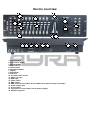
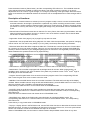
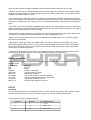
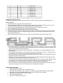
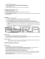
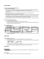
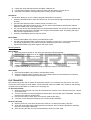
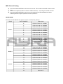
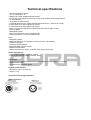
OSO 1612 operator
DMX controller
User manual
Safety instructions
WARNING!
Always keep this device away from moisture and rain! Hazardous electrical shocks may occur!
WARNING!
Only connect this device to a matching power outlet. This device is intended to work on a
specified AC currency. Connecting this device to power outlets with other voltages may result in
permanent damage and possible hazardous situations, such as fire or electrical shocks!
WARNING!
Be careful with every operation of this device. Touching live wires inside and outside the unit
may cause hazardous electrical shocks!
This unit must be operated by, or under the supervision of an adult. This device is not suitable for children.
Every person involved with the installation, operation and maintenance of this device has to:
- Be qualified
- Follow the instructions of this manual
- Make sure there is no damage caused by transport. If the device seems damaged from the outside, do not
use it and contact your dealer for more information and consultation.
- To make sure the device maintains in perfect condition and for safe operation, it is necessary for the user to
follow the instructions and warning notes of this user manual.
- Damage caused by improper use or modifications to the device are not covered by warranty.
- This device does not have any user-serviceable parts inside. Servicing of this device needs to be done by
qualified technicians.
Important notes regarding safety and health:
- Never let the power cord come in contact with other cables. Handle the power cord and all connectors with
the mains with caution.
- Never remove any warning or informative labels from the unit
- The ground contact always needs to be connected. Do not cover or remove the ground contact.
- Never leave cables lying around
- Do not open the device and do not modify any hard- or software of this unit.
- Do not insert this object into air vents.
- Do not connect this device to a dimmerpack.
- Do not switch the system on and off frequently as this will reduce the lifespan of the device.
- Do not drive the inputs of the fixture with a signal larger than required to work at full performance.
- Only use this device indoor, avoid contact with water, moist or other liquids. Do not place items filled with
liquids on top of the unit.
- Avoid nearby flames or heat sources, do not place this device near flammable liquids, gas or flammable
items.
- Always disconnect the device when it is not in use for a longer period or time, when servicing is needed or
when the device needs cleaning.
- Only handle the power cord by its connectors. Never pull the cable to remove a connector from its socket,
as this could lead to damage and electrical shocks.
- Always operate this device with a stable AC current.
- Always operate this device with the AC ground wire connected to the electrical system's ground.
- Never use other types of cables than specified in the manual, do not use defective or bad functioning
cables. Contact your dealer when the included or required cables do not work properly with this device.
- When the device has been exposed to large temperature differences (for example, transport from outdoor
to indoor), do not connect the device immediately. Do not activate the unit until it has reached room
temperature, as moist might build up inside the unit, which may cause shortcuts and/or electrical shocks.
Guidelines and types of use:
- This device is intented to be used by professionals on stage, in theatres, clubs and other equal venues.
- This device is not suitable for children and always needs to be operated by an adult.
- Only use the device when the environment is suitable and will not cause any damage. Do not use the
product in moist or dusty environments, or where long-term damage may occur such as:
- indoor swimming pools where chlorine is used.
- Beaches, where sand and salt are present.
- Outdoor, without roof protection
- Indoor areas where intense heat sources are present or where the temperature exceeds levels
which are comfortable for humans.
- Only use the included power adapter and only connect the device to a suitable power outlet with the correct
output voltage. Connecting the device to a power outlet with the wrong type of voltage or using the prodcut
with a wrong type of power supply may cause permanent damage to the device.
- Avoid shocks and collission during use and transport. Do not transport the device while in use. Avoid brute
force during the installation and operation of this device.
- Familiarise yourself with the functions of the device before use. Do not allow operation of the device by
unskilled or unqualified people.
- Use of the device in other ways than described in this user manual may cause damage and injury. Ayra
does not take responsibility for any damage or injury caused by improper use.
Storage and transport:
- This device is intended for mobile use. When transported, use the original packaging of the product, or a
fitting flightcase, preferably filled with foam.
- This device is not intended for permanent use. Operation breaks will ensure that the lifespan of the device
remains unchanged.
- If the device is not used for a longer period of time, disconnect it from its power source and store it in its
original packaging, or in a fitting flightcase.
- Store the device indoor, dry and do not expose the device to extreme temperature differences.
Housing:
- Inspect the housing of the device frequently. Severe dents, cracks and missing screws should be avoided
at all costs. Do not use the device when the housing is not in optimal condition. Contact your dealer or a
skilled technician when in doubt about the state of the device
- Check the fixture and screws for corrosion. Corrosion should not be present on the fixture. Contact your
dealer or a skilled technician when corrosion is found on the fixture
- Every power or signal chassis/connector should be mounted tightly. Do not use the device when connectors
are loose.
- Do not use the power cord when the cores are visible. Contact your dealer for a replacement if needed.
- Avoid the buildup of dust and dirt. Clean the exterior of the fixture every month with a dry or damp cloth.
When using the device intensively, the cleaning frequency needs to be increased.
Fuses:
- The main fuse of this device is to be found on the rear of the device. In most cases, directly next to the
power inlet.
- Only replace a fuse for a new one with the same type and rating! Do not use a fuse with a higher or lower
rating.
- Do not bridge the fuse with electrical wires, aluminum foil, as the fuse is used for protection against
electrical shocks and short circuit.
- Always mount the fuse cover back to the fuse compartiment.
Box contents
Box contents
1x OSO 1612 console
1x power supply
Unit and accessory inspection
- Always check the unit, box and accessories for possible damage before use. If you suspect that something
is wrong with the unit, do not connect it to a power source! When you suspect that your unit is broken or
damaged, contact your local dealer or a certified technician to inspect the unit.
- If any of the parts that should be included is missing, contact your local dealer for help.
- If the box appears severely damaged, soaked with liquid or ripped apart, do not unpack the product and
contact your local dealer for help and more information.
- Always preserve the original box and packaging materials as long as the warranty period is active. This
way, the device can be transported for repair and inspection safely.
Device overview
2
10
4
7
1
3
5
6
10
19
10
8
11
12
13
14
15
9
16
1. Fixture buttons
2. Fog machine button
3. Page A/B LEDs
4. Scene buttons
5. Fixture faders
6. Page Select button
7. Display
8. Speed fader
9. Fade time
10. Program button section
11. Audio line input
12. MIDI input
13. Phase switch
14. DMX output
15. DMX controller input (Note: Not for DMX, but for data exchange / file dump!)
16. Power supply input
17. On/off switch
18. Fog machine control output (not for power supply!)
19. Movement joystick
17
18
Use of the controller
GENERAL DESCRIPTIONS:
a. There are 192 channel outputs selectable in every scene. Every channel may have a value between 0
and 255.
b. Each bank may contain 8 different scenes. When playback of scenes is activated, the scenes in a bank
will run in a continuous cycle.
c. Select the desired bank using the UP and DOWN buttons. You may also select the desired bank using
MIDI signals through the built-in MIDI interface There are 30 banks for scene storage, it is not possible
to select several banks at once.
d. Scenes can be executed automatically, and the duration depends on the desired speed, selectable
with the SPEED fader and TAP SYNC button. Scenes are executed under music triggering or NOTE
triggering. Scenes can be triggered manually by using the SCENE buttons in every bank.
e. There are 6 chases which can be programmed freely. Each may contain 240 scenes.
CONTROLS & FUNCTIONS
Scanners(1-12)
Scanners
1
2
3
4
5
6
7
8
9
10
11
12
Scanners
1
2
3
4
5
6
7
8
9
10
11
12
Channel
1-16
17-32
33-48
49-64
65-80
81-96
97-112
113-128
129-144
145-160
10-176
177-192
Fade control
OFF
OFF
OFF
OFF
OFF
OFF
OFF
OFF
OFF
OFF
OFF
OFF
LED
OFF
OFF
OFF
OFF
OFF
OFF
OFF
OFF
OFF
OFF
OFF
OFF
Channel
1-16
17-32
33-48
49-64
65-80
81-96
97-112
113-128
129-144
145-160
10-176
177-192
Fade control
ON
ON
ON
ON
ON
ON
ON
ON
ON
ON
ON
ON
LED
ON
ON
ON
ON
ON
ON
ON
ON
ON
ON
ON
ON
Press the desired scanner (fixture button), and the corresponding LED will turn on. The individual channels
of the selected fixture are enabled to change the values, even when scenes are running, for on-the-fly
adjustments such as a colour or gobo change, or a change in positioning of the light output. When the fixture
button is de-selected, the individual channels of the fixture can not be adjusted and no visible changes will be
seen.
Description of functions:
- Scene button: Press this button to activate (or store in program mode) a scene. A scene can be described
as a static situation, where light is positioned in a particular way. When combining several scenes, a chase
can be made. A chase consists of several scenes, played in a continouos loop. Thanks to changing values
(movement or colours), the actions of your lighting will change every time another scene is activated in the
chase.
- Channel faders: Each fixture button has 16 channels. For every fixture, there are 8 physical faders, with A/B
page functionality so the faders can work on channel 1-8 or 9-16 thanks to a switch. Each channel fader
can be set to a value between 0 and 255.
- Page select: Switch from page A (1-8) to page B (9-16) and vice versa.
- Speed fader: Use the speed fader during playback of a chase. With the speed fader, the speed of changing
scenes can be set. This can be very fast (0.1s) or very slow (10 minutes) and everything in between.
- Fade time fader: Move the slider to adjust the fade time. The fade time controls the amount of time it takes
for a scene to go from one value to another. This way you can control fluent color changes (with RGB LED
fixtures) or fluent movement of your intelligent lighting (such as scanners or movingheads). Find the optimal
balance between the speed and fade time by experimenting.
- LED display: Showing chase, scene and bank information. Also shows LED indicators for Blackout, STEP,
Prog, Auto trigger and Music trigger.
- Joystick: Control the pan and tilt movement of intelligent moving light (movingheads, scanners). You always
need to patch the joystick to the pan/tilt channels of your devices. With the override buttons the selected
channels/fixtures can be overtaken during live use in a chase or scene.
- Chase buttons: Used to trigger one of the 6 chases, or used to select a chase when programming.
- Bank buttons: The controller is equipped with 30 storage banks for scenes. When programming, it is
possible to store scenes in one of the 30 banks. Every bank may contain 8 scenes. The 3 rd and 4th digit on
the display show the selected bank.
- Program: Press Program button for 2 seconds to enter the program mode. The corresponding LED will
blink. Press Program once more to return to the live mode.
- MIDI/Rec: Press the MIDI button when the controller is activated. The third and fourth digit of the display
will flash. Select the MIDI channel using the UP and DOWN buttons, press the MIDI button once more or any
other key excluding UP or DOWN to end the MIDI channel settings.
Press this key to make scenes or record chases when in PROGRAM mode.
- Auto/DEL: When in the RUN mode, press Auto/Del to activate the automatic chase run sequence. The
corresponding LED will turn on. Press the button once more to exit the automatic mode, the corresponding
LED will turn off.
Press this button to delete scenes and chases when in PROGRAM mode.
- Music/Bank copy: When in the RUN mode, press this button to activate the MUSIC mode. The
corresponding LED will turn on. Press the button once more to exit the MUSIC mode, the corresponding
LED will turn off.
Press this key to copy banks when in PROGRAM mode.
- Tap sync / display: When in AUTO RUN mode, use the TAP SYNC function to determine the amount of time
between two steps. This way it is possible to tap the button on the beat of the music, for music-synchronised
shows. The maximum amount of time between two steps is 10 minutes.
When in PROGRAM mode, use the button to switch between Step and Bank mode. When in any other
mode, use this function to toggle the displayed channel-values between 000-225 and 0%-100%.
- Blackout: Press this key to disable all visible output of the channels. The functions of the controller remain
available, for example when you want to change a chase in the climax of the music, or to activate a special
function to release at a specific moment.
- Fog machine button: Some fog machines are able to be used with this controller. When pressing the FOG
button, the controller sends a signal to the connected smoke machine and a 100% output will be activated on
the machine. Working with every smoke machine is not guaranteed as there are many different brands and
types.
- Fine button: This controller supports intelligent lighting fixtures with 16-bit pan/tilt movement. In most cases,
there are separate fine pan/tilt channels for optimal positioning of the beam. With the fine button, the joystick
switches from regular movement to fine movement.
- Mode button: To assign channels to the joystick or to invert the signal while using the joystick, the fine and
mode button should be pressed at the same time to enter the configuration menu.
- MIDI in: Use this 5-pin DIN connector to receive MIDI data from a MIDI-device, such as a button trigger,
keyboard or footcontroller.
- DMX polarity: Select the polarity of the DMX output. This function needs to be used when you use old
Martin lighting effects (Martin Protocol). The function inverts the signal of pins 2 and 3. When your lighting
fixtures don’t correspond properly to the values of the controller, switch the polarity to make sure that this
function does not cause the problem.
- Use this 3-pin XLR output to connect all of your DMX lighting fixtures. By daisy-chaining the fixtures and
selecting the proper DMX-adresses, it becomes possible to control every single fixture.
Display Information:
The LCD Display contains a maximum of 2 lines, each of 8 characters. Below are the definitions and
example values.
LCD Display
SN1
BK1
CHASE1
STEP 009
DATA 184
SP: 1M54s
TP: 4.25s
ASS 04 05
RES 10 13
Message
Scene 1
Bank 1
Chase 1 is activated
The ninth step of a chase
DMX Value (000-255)
The current speed is 1 minute 54 seconds
The time of the last two taps is 4.25 seconds
Assign DMX channels 4 and 5
Reverse DMX channels 10 and 13
SET UP
Unit Setup
The unit is preset to allocate 16 channels per fixture. In order to assign your fixtures to the scanner buttons
located on the left side of the unit you will need to space your fixtures 16 DMX channels apart.
Use the Following chart for DMX Addressing
Fixture #
1
Digital #
1
Dip Switch Setting
1 “On”
2
17
1 and 5 “On”
3
33
1 and 6 “On”
4
49
1,5 and 6 “On”
5
6
7
8
9
10
11
65
81
97
113
129
145
161
1 and 7 “On”
1,5 and 7 “On”
1,6 and 7 “On”
1,5,6 and 7 “On”
1 and 8 “On”
1,5 and 8 “On”
1,6 and 8 “On”
12
177
1,5,6 and 8 “On”
Enabling the program mode
To enable program mode, hold the program button for a few seconds until the corresponding LED is lit.
Set-up Joystick
1. Press and hold the “Program” button until LED is lit.
2. Press and hold the “Mode” and “Fine” button at the same time, the assign LED should turn on. If the
reverse LED lights, press “Fine” and “Mode” again to enter assign mode.
3. Use the bank UP and DOWN keys to select the axis you wish to assign (Pan or TILT).
4. Use the “Tap/Display” button to select 16 or 8 channel mode.
5. Press the button corresponding to the scanner you wish to assign.
6. While holding the mode button press the scene number corresponding to the slider which controls the
movement. (Example: If pan is controlled by slider number 4, press and hold the “Mode” button while
tapping scene button 4#).
7. When finished press the “Mode” and “Fine” buttons at the same time again to exit Assign mode.
SCENES
Programming A Scene
a. Enter program mode (See Enabling Program Mode)..
b. Check the blackout key and verify that the LED is not lit, if it is, press it once to exit blackout mode.
c. Verify that the speed and fade time sliders are positioned at zero.
d. Press the scanner (fixture) button corresponding to the unit wish to control. You may control more than
one scanner at time by pressing the button corresponding to the scanner(s) you wish to program. The
values of each fixture will be synchronized.
e. Move the faders and joystick to the desired position. If necessary, you may select page B to control
channels 9-16.
f. Tap the bank Up/Down button to choose the bank you want to store this scene into. There are a total
of 30 banks you can select, you may store up to 8 scenes in each bank.
g. Once all scanners are programmed into the desired position for the scene, tap the MIDI/Rec button to
program this scene into the memory.
h. Tap the scene button you wish to store your scene into. All LEDs will flash three times signifying this
operation. The LCD readout will show the bank and scene.
i. To unselect the scanner(s) you have been programming and switch to another simply press the button
of the scanner you have been programming again, deselecting it, and select another scanner.
j. Repeat steps 2-7 until all scenes (or the amount you want) have been programmed.
k. If you don’t intend to continue programming at this time, press and hold the program button for three
seconds to exit program mode. The LED will go out indicating this selection.
Example Scene Program
a. Enable the program mode.
b. Tap the Scanner 1 button to turn on its fader control.
c. Verify that the page select is set on page A, if not press the page select button to select page A.
d. Move the first and second faders all the way up to their maximum value position.
e. Select bank 1 using the bank Up/Down buttons.
f. Press the MIDI/Rec button.
g. Tap scene 1 to store the first scene.
h. Repeat steps 4-7 until all scenes have been programmed into bank 1.
i. Tap the scanner 1 button to turn off the fader control.
j. When finished, disable program mode. You can now manually tap through you have just
programmed.
Editing A Scene
a. Enable the program mode.
b. Press the Bank Up/Down button to select the bank containing the scene you wish to edit.
c. Select the scene you wish to edit by tapping it’s scene button.
d. Use the faders and/or joystick to make the desired adjustments to the scene.
e. Once you have completed the changes, tap the MIDI/Rec button.
f. Tap the scene button that corresponds to the scene you’re editing. This will override the existing
scene.
Be sure to select the same scene in steps 3 and 6, otherwise you may accidentally record over an
existing scene.
Copy Scanner Settings
This setting allows you to copy the settings of one scanner (fixture) to another
a. Press and hold down the scanner (fixture) button you wish to copy.
b. While holding down the button, tap the button of the scanner you wish to copy the settings to.
Copy A Scene
1) Enable Program Mode.
2) Tap the Bank Up/Down button to select the bank containing the scene you wish to copy.
3) Select the scene you wish to copy by pressing the corresponding scene button.
4) Using the BankUp/Down button select the bank you wish to copy the scene to.
5) Tap the MIDI/Rec button.
6) Tap the scene button you wish to copy the scene to.
Deleting A Scene
a. Enable Programming Mode.
b. Press the desired Scene button to select the scene you wish to delete.
c. Press and hold down the Auto/Del button. While holding the button, tap the scene button that
corresponds with the scene you wish to delete.
d. When the programmed scene is deleted, all DMX channel values will be set to 0.
Deleting All Scenes
1. With the power off to the unit, press and hold down the Program and Bank Down buttons at the same
time.
2. Turn the unit back on, and all scenes should be cleared.
Copy A Bank of Scenes
1) Enable Programming Mode.
2) Tap the Bank Up/Down button until you reach the bank you wish to copy.
3) Tap the MIDI/Rec button.
4) Tap the Bank Up/Down button to select the bank you wish to copy to.
5) Tap the Music/Bank Copy button, all LEDs will briefly flash three times indicating the function has
been completed.
6) Press the program button for three seconds to exit programming mode.
CHASES
Programming a Chase
Note: You must have already programmed scenes in order to program a chase, this function allows you
to cycle through up to 240 scenes in a preselected order. It is recommended before programming
chases for the first time, you delete all chases in the controller. See Delete All Chases for instructions on
how to do so.
a.
b.
c.
d.
e.
Enable Programming Mode.
Tap the Chase button to select the chase you wish to program.
Select a desired scene from the bank that has scenes stored inside it.
Tap the MIDI/Rec button.
Repeat steps 3-4 until all desired scenes scenes have been entered.
Inserting a bank of scenes into a chase
7. Enable Programming Mode.
8. Select the chase you wish to program.
9. Use the Bank Up/Down key to select the bank of scenes you wish to copy.
10. Tap the Music/Bank Copy button.
11. Tap the MIDI/Rec copy button, all LEDs will flash three times indicating that the requested operation has
been performed.
Add A Step
1) Enable Programming Mode.
2) Press the corresponding button to the chase you wish to add a step to.
3) Press the Tap/Display button, the display will show the current step.
4) Press the Bank Up/Down button and scroll to the step you wish to insert the step after.
5) Press the MIDI/Rec button, the segment display will read the step one step higher than before.
6) Tap the Tap/Display button again. The display shows the current chase, scene, and bank. Create a
desired scene and record it as a new step or select a previously programmed scene to add to the
chase.
7) Once you have selected the scene you wish to add, press the MIDI/Rec button again. All LEDs will
flash three time indicating the new step has been inserted into the chase.
Deleting A Step
1) Enable Programming Mode.
2) Select the chase that contains the step you wish to delete.
3) Press the Tap/Display button, the LCD shows the current step.
4) Press the Bank Up/Down button and scroll to the step you wish to delete.
5) Press the Auto/Del button to delete the step. All LEDs will flash three times indicating the requested
operation has been performed.
Delete A Chase
1. Press the button corresponding to the chase you wish to delete.
2. Press and hold down the Auto/Del button while holding down the chase button. All LEDs will flash three
time indicating that the requested operation has been performed.
Delete All Chases
1. With the power off, press and hold down the Auto/Del and Bank Down buttons at the same time.
2. Reapply the power, and all chases should be cleared.
JOYSTICK/CHANNEL SELECTION
Set-up Joystick
a. Press and hold the “Program” button until LED is lit.
b. Press and hold the “Mode” and “Fine” buttons at the same time, the assign LED should light. If the
reverse LED lights, press “Fine” and “Mode” again to enter assign mode.
c. Use the bank Up and Down keys to select the axis you wish to assign (Pan or Tilt).
d. Use the “Tap/Display” button to select 16 or 8 channel mode.
e. Press the button corresponding to the scanner you wish to assign.
f. While holding the mode button press the scene number corresponding to the slider which controls the
movement. (Example: If pan is controlled by slider number 4, press and hold the “Mode” button while
tapping scene button 4#).
g. When finished press the “Mode” and “Fine” button at the same time again to exit
ASSIGN MODE
Reverse Joystick Movement/DMX Channel
a. Enable Programming Mode.
b. Press the Fine and Mode buttons to enter assign mode, then press Fine and Mode buttons again to
enter reverse mode. The reverse LED lights up indicating reverse mode is active.
c. Use Bank Up/Down button to change between the Pan and Tilt, the corresponding LED lights indicating
this selection.
d. Press the Tap/Display button to change between 8 CHANNEL and 16 CHANNEL mode.
e. Press the scanner button to select the scanner (fixture).
f. While holding the mode button, press the corresponding scene button the channel you wish to reverse.
(For Example: If you are reversing the on one scanner, once you verify that you are in reverse mode,
and the Tilt LED is lit, check to see which slider the Tilt control is on. Hold the mode button and press
the scene button that is same as the slider number for tilt. (Slider 5/Scene 5).
g. Continue steps 3-7 as needed. You may reverse a maximum of 48 channels for 12 scanners (fixtures).
Delete a scanner of DMX Channels
a. Activate Assign or reverse mode.
b. Tap the scanner button to select the scanner you wish to delete.
c. Press the mode and Auto/Del buttons at the same time. All LEDs will flash three time indicating the
requested operation has been performed.
Clear All DMX Channels
a、 Turn the power off.
b、 Press the Mode and Auto/Del buttons at the same time.
c、 While holding the two buttons, turn the power back on to the unit. All LEDs will flash briefly indicating
the requested operation has been performed.
Display DMX Channel
1) Press the Fine and Mode buttons at the same time, putting the controller into assign mode.
2) Press the Fine and Mode buttons again, lighting the reverse LED.
3) Press the scanner button that is set at the desired Pan and Tilt and the display will show the DMX
values for Pan and Tilt.
FADE TIME
Fade Time/Assign Fade Time
1) With the power off, press the mode and Tap/Display buttons at the same time.
2) Apply the power again, tap the Tap/Display button to change between Fade Time and Assign Fade
Time, the LCD reads
ALL
FD
3)
CH
TIME
OR
ONLY
FD
X/Y
TIME
Press the Mode and Tap/Display buttons at the same time to store your setting into memory. If you
do not wish to save your setting, press the blackout key to exit this operation.
PLAYBACK
Running Scenes
There are three modes in which you can run scenes and chases. They are Manual mode, Auto mode,
and music mode.
Manual Mode
1) When the power is turned on, the unit enters manual mode automatically.
2)
3)
4)
Check and verify that both the Auto and Music LEDs are off.
Use the Bank Up/Down button to select the bank with the scenes you wish to run.
Press the scene button corresponding to the scene you wish to display.
Auto Mode
This function allows you to run a bank of programmed scenes in sequence.
a. Press the Auto/Del button to enter into Auto mode. The Auto LED will light indicating the Auto mode
is active.
b. Use the bank Up/Down button to select a bank of scenes to run.
c. After selecting the bank of scenes to run, you can use the speed slider and Fade Time slider to
adjust the speed of the scene progression.
d. You can use the Tap Sync/Display button to set the speed instead. The amount of time between the
last two taps will instruct the controller in the length of time between steps. This setting will stay in
effect until the speed slider is moved.
e. Press the Auto/Display button to exit Auto mode.
Music Mode
a. Press the Music/Bank Copy button to activate Music mode.
b. Use the bank Up/Down button to select a bank of scenes you wish to run. The scenes selected will
run through sequentially to the beat of the music identified by the built-in microphone.
c. Tap the Music/Bank Copy button again to exit music mode.
Running Chases
Manual Mode
1) When the power is turned on, the unit enters manual mode automatically.
2) Select the chase you wish to run by pressing the corresponding chase button. Pressing this button
a second time will unselect the chase.
Auto Mode
1) Press the Auto/Del button to activate Auto mode.
2) Select the desired by pressing one of six Chase buttons. Pressing this button a second time will
negate this selection.
3) Use the speed slider and Fand time slider to adjust the chase to your specifications.
Music Mode
1) Press the Music/Bank Copy button to activate Music mode.
2) Select the desired chase by pressing one of six Chase buttons, this will activate the chase and
cause it to respond to the rhythms of the music.
FILE TRANSFER
File Transfer allows the user to transfer all information stored in one controller to a second unit. You must
connect the units using 3-pin XLR cables. Connect the XLR-cable to the DMX “Out” chassis on the sending
controller and use the DMX “In” chassis on the receiving unit.
To Send A File Dump
1) With the power off to the unit, press and hold down the scanner 2 and 3 buttons and scene 1 button
at the same time.
2) Turn the unit back on while pressing these three buttons, the LCD will read “TRANSMIT” indicating
that the unit is ready to send the files.
3) Press scene button 7 and 8 at the same time to send the file dump.
4) If an error occurs during the file dump, the LCD will readout “ERROR”.
Receive File Dump
1) With the power off, press and hold down the scanner 8, 9 and scene button 2 at a time.
2) Apply the power again while pressing these three buttons, the LCD shows “RECEIVE” indicating
this unit is receiving the file dump.
3) After receiving the data, the unit will automatically return to normal mode.
MIDI Channel Setting
1)
2)
3)
Press and hold the MIDI/Rec button for three seconds. The LCD shows the MIDI channel of last
time.
Use the bank Up/Down button to select the DMX channel 01-16 to assign to the MIDI channel.
Press and hold the MIDI/Rec button to save your settings. The LEDs will flash three times
indicating that the required operation has been performed.
MIDI RUNNING
NOTE ON: Receive NOTE ON signals to execute corresponding function.
BANK
BANK1
BANK2
NOTE NUMBER
00
TURN ON TURN OFF SCENE1
01
TURN ON TURN OFF SCENE2
02
TURN ON TURN OFF SCENE3
03
TURN ON TURN OFF SCENE4
04
TURN ON TURN OFF SCENE5
05
TURN ON TURN OFF SCENE6
06
TURN ON TURN OFF SCENE7
07
TURN ON TURN OFF SCENE8
08
TURN ON TURN OFF SCENE1
09
TURN ON TURN OFF SCENE2
10
TURN ON TURN OFF SCENE3
”
BANK15
CHASE
FUNCTION
”
112
TURN ON TURN OFF SCENE1
113
TURN ON TURN OFF SCENE2
114
TURN ON TURN OFF SCENE3
115
TURN ON TURN OFF SCENE4
116
TURN ON TURN OFF SCENE5
117
TURN ON TURN OFF SCENE6
118
TURN ON TURN OFF SCENE7
119
TURN ON TURN OFF SCENE8
120
TURN ON TURN OFF CHASE1
121
TURN ON TURN OFF CHASE1
122
TURN ON TURN OFF CHASE2
123
TURN ON TURN OFF CHASE3
124
TURN ON TURN OFF CHASE5
125
TURN ON TURN OFF CHASE6
126
BACKOUT
Technical specifications
- 192 channel DMX controller
- 19 inch construction, 3U
- designed to control intelligent lighting devices
- for use with movingheads, scanners and other types of DMX controlled light effects
- 12 fixture buttons
- 16 channels for each fixtures
- 8 physical faders for each fixture (with A/B page function for 1-8 and 9-16 control)
- 8 scene buttons for easy triggering of scenes
- 6 chase buttons for easy triggering of chases
- faders for speed and fade time for fluent speed and value change controls
- black-out button
- DMX polarity switch
- built-in microphone for sound controlled mode
- audio input mode for sound controlled shows
Extra:
- Assignable joystick
- Fade Time assign to X/Y channels (or other channels, soft-patched)
- Pan/tilt fine support
- File Dump transfer support
- Reversible DMX channel outputs
- Manual override button
- Built-in microphone for sound controlled mode without audio input
Power requirements:
- Fixture working voltage: 9-12V DC, 300mA
- Power supply working voltage: 230V AC, 50Hz
Connectors:
- 3P XLR in/out for DMX and data transfer (data transfer only with supporting consoles)
- 5-pin DIN MIDI input
- fog machine IEC output for signal
Physical characteristics:
- Dimensions: 482 x 134 x 85 mm
- weight: 2.7 kg
Connectors and wiring schematics:
DMX-connections: