1
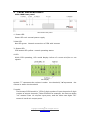
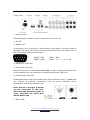
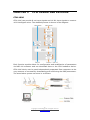
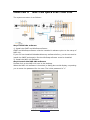
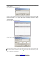
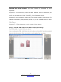
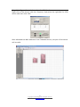
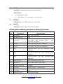
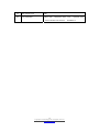
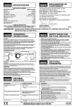
CFM Conference Mixer Product Manual CFM Conference Mixer Product manual The information contained in this manual is subject to modify without notice. Copyright © 2009-2010 All rights reserved by DigiSpider Inc. This publication contains information that is protected by copyright. “DS” , “Digispider”, “Dspider” mentioned in this manual all refer to” DigiSpider Inc. No part of it may be reproduced, transmitted, or translated any language without permission from DigiSpider Inc. Trademarks as “DS”, “Digispider”, “ Dspider” used in this manual are registered by DigiSpider Inc.Trademark as “Intel” is registered by Intel Corporation; Trademarks as “Microsoft”, “MS-DOS”, “Windows”, “Windows 98”, “Windows 2000”, “Windows XP” are registered by Microsoft Corporation; Other trademarks and Names mentioned in this manual are belong to the corporation who have registered the trademark or produced the product. DigiSpider Inc.has no patent right for these products. CFM Series Mar. 2010 P/N: Version: 1.0 1Copyright © 2009 Digispider. All rights reserved. www.digispider.net CFM Conference Mixer Product Manual Thanks for your purchasing CFM conference mixer developed by our company. Human and high-tech essences are fused in our products. CFM series will give you one brand-new application experiences. Please follow the steps to protect your products, work area and personal safety, in order to avoid the potential danger of damage. When you are using CFM equipments: Please follow the steps when you are using CFM equipments, Warning: Don’t operate CFM equipments when you demount the z covers (including cover, front panel, and back panel and so on). Please make sure the Voltage of the CFM according to local AC voltage standard, in order to avoid to damage CFM equipments. --There are 115V/60Hz in most of countries and districts in South America, North America and Far East, e.g. Japan, Korea and Taiwan. --There are 230V/50Hz in most of countries in Europe, Middle East and Far East. z Please make sure the electrical outlet is unplugged before interior setup of CFM equipments, in order to avoid to damage main board of CFM equipments. Some main boards are electrified still when the equipment is plugged. z Installation and servicing should be performed by qualified and experienced personnel. z Please make sure all the cables of CFM equipments and peripheral equipment are connected to the correct ground electrical outlets, in order to avoid electrical shock. All the cables are equipped three-phrase plug to ensure they are grounded correctly. Don’t use the unidirectional plug and don’t remove the pins from the cable. Please use three-phrase cable with correct ground electrical outlet if you need to use extension cords. z Don’t use CFM equipments in thunderstorm, in order to avoid the potential risk of electrical shock. z Don’t connect or disconnect any cable and don’t repair or reconfigure the product in thunderstorm, in order to avoid the potential risk of electrical shock. z Please make sure the connection of CFM equipments and electrical outlet is severed before cleaning. z Make sure that CFM equipment’s power is off when you clean it. Clean your CFM equipment exterior casing regularly with a soft and dry cloth or a fluff brush. Do not use liquid or aerosol cleaners which maybe include caustic or flammable substance. z Wait for a period about ten seconds before severing the connection of peripheral equipment and CFM equipment, in order to avoid damage to the system board. 2Copyright © 2009 Digispider. All rights reserved. www.digispider.net CFM Conference Mixer Product Manual z Pull out the cable from the network adapter which is on the back of CFM equipment first and then pull out the cable from the network hole, in order to avoid short circuit when you sever the connection. Plug the cable into network hole first and then plug the cable into network adapter when you reconnect the products. z Please use surge protective device, circuitry adjuster and UPS, in order to avoid instantaneous high or low voltage damage to CFM equipment. z Make sure there are no goods exert pressure on cables. Do not make cables exposure, which will cause trample and stumble. z Never push objects of any kind through openings of CFM equipment as that may cause interior short circuit and result in fire, electric shock, or other hazards. z Do not use CFM equipment near a source of heat and don’t jam the refrigeration vent. Don’t make paper underlie CFM equipment. Use CFM equipment in ventilated area and don’t locate CFM equipment on bed, sofa or carpet. z Never spill food or liquid of any kind on the CFM equipment. z Do not use the CFM near water or other liquids, or in rainy/moist situations. If liquid gets into your CFM, turn it off and take it to your dealer for inspection. z Water and/or Moisture Do not use this equipment near water or in contact with water. Technical instructions Warning: Perhaps there are some mistakes of description and printing in technical instructions z With the rapid technical development, our products keep on improving and renewing, so there are may some demoded or useless specifications about some standards in this manual. z We are very conscientious for reorganizing this manual, but we do not guarantee there is no negligence or mistake in this manual, and we can't exclude the possibility that this manual will be renewed again. If there are any revises, we will not give notice any more. z If there is any revises in this manual, it will be promulgated in Digispider Website:http://www.digispider.net 3Copyright © 2009 Digispider. All rights reserved. www.digispider.net CFM Conference Mixer Product Manual Do not tear up any label Warning: Please do not voluntarily tear up any label on CFM equipment; otherwise it will affect to recognize the standard of product maintenance deadline. z All labels on CFM equipment show information when the products are manufactured and sold, these labels are very important for technology recognition and maintenance of products. z All labels on CFM equipment are belonged to recognized standard of product maintenance deadline. If you voluntarily tear up them, it will affect to recognize the standard of product maintenance deadline. Looking for help Warning: Do not attempt to repair this equipment yourself, or it will damage your equipment and result in serious results, e.g. personal injury. z All CFM products are manufactured by DigiSpider Inc.,All maintenance should be performed only by authorized Units. z Do not attempt to repair this equipment yourself. Refer all repairs to qualified service personnel. z If there is any question, please contact the dealer you purchased CFM equipments from, you also can call Digispider customer service, ask for help. 4Copyright © 2009 Digispider. All rights reserved. www.digispider.net CFM Conference Mixer Product Manual Table of Contents ABOUT THIS GUIDE ...................................................................................................................... I HOW TO USE THIS MANUAL........................................................................................................ I ANNOUNCEMENT AND PROVISIONS....................................................................................... II CHAPTER 1 1 2 CFM SYNOPSIS .................................................................................................3 CFM TYPE LIST.........................................................................................................................3 FRONT AND REAR PANEL: ...................................................................................................4 CHAPTER 2 CFM OPERATING PROCESS........................................................................8 CFM-1006 .........................................................................................................................................8 CFM-0800 .......................................................................................................................................12 CHAPTER 3 BASIC OPERATION.......................................................................................14 STAND ALONE MODE ..................................................................................................................14 EXPAND MODE ..............................................................................................................................15 NETWORK MODE ..........................................................................................................................16 CHAPTER 4 NSP-100 QUICK START FOR CFM.........................................................17 CHAPTER 5 TECHNIQUE SPECIFICATION .................................................................29 1 2 3 4 ANALOG AUDIO INPUT SPECIFICATION.........................................................................29 ANALOG AUDIO OUT PUT SPECIFICATION....................................................................29 INTERFACE SPECIFICATION...............................................................................................29 OTHER SPECIFICATION........................................................................................................29 CHAPTER 6 FAQS .....................................................................................................................30 CHAPTER 7 GLOSSARY .........................................................................................................31 APPENDIX CFM SERIAL PORT CONTROL PROTOCOL..........................................33 5Copyright © 2009 Digispider. All rights reserved. www.digispider.net CFM Conference Mixer Product Manual ABOUT THIS GUIDE This manual will help you to be acquainted with the products and functions of CFM Series Conference Mixer, by presenting the methods of installation, configuration, operations and maintenance. If you encounter any problem, or it is the first time for you to use Digispider’s CFM Series, please read this manual first for relevant information and technical supports. As for its upgrades and updates, some descriptions and illustrations in the manual may be different with your hardware. Please visit http://www.digispider.net from time to time for the latest documentation. HOW TO USE THIS MANUAL Read it in any order you like. You may begin with any page and skip to the desired one. It will surely provide you with a complete flowchart if you read it from the beginning to the end. There are Table of Content and Index in the manual, providing different research methods for various reading habits. If you encounter any unknown words or expressions, please refer to the attached “Glossary”. For the person who use the system for the first times: We recommend you read all the content of the manual, especially the information with words of “Note, Caution and Warning”. You are required to operate strictly according to the prospectuses in the manual. During the installation of hardware, frequently read the “Safety Guidelines” section of the manual. For ordinary users As for system administrator and operator, they may read the necessary information at their own choice. Please refer to the “General description” section of the manual for specific description. If the manual can't solve the problem, please contact the technical support personnel and trained & qualified engineers for the solution. For experienced and qualified engineers: For the reason that our products keep on upgrading and updating, please make attention to the update information of the manual. The specific update information is easily accessible at the all time on our service and support website, which will be incorporated into the last version of manual. iCopyright © 2009 Digispider. All rights reserved. www.digispider.net CFM Conference Mixer Product Manual ANNOUNCEMENT AND PROVISIONS The manual prepared by Digispider Inc. does not provide any form of guarantee, clear or implied, including but not limited to, implied guarantees or a special-purpose commercial reasonableness. In some areas of specific transactions is a clear or implied guarantees, therefore, this statement may not apply to you. The manual may contain technical inaccuracies or typographical errors terminology. Identify changes and updating information regularly updated content will be updated to version. Digispider Inc may make improvement or updates for the products and procedures described in this document, at any time as it sees fit. The manual applies to CFM Conference Mixer configured with different channels. For more technical information, please consult your Digispider Inc sales representative and retailers. The usage, reproduction and distribution of this manual are subject to Digispider Inc’s provisions. Without the prior written permission obtained from Digispider Inc, this manual shall not be reproduced and distributed. © 2009-2010 Digispider Inc All Right Reserved The power of interpretation of the manual shall be vested in Digispider Inc. iiCopyright © 2009 Digispider. All rights reserved. www.digispider.net CHAPTER 1 CFM SYNOPSIS CFM is an intelligent conference mixer dedicated designed for all forms of conference discussion systems. Using CFM conference mixer, it would be quite a cozy job to create a conference system, just by connecting the external equipments such like microphones and speakers etc. 1 CFM TYPE LIST There are two different types of CFM intelligent mixer to meet the demands of different requests of different sorts of conferences. They are: CFM-1006 conference host computer and CFM-800 conference extended unit. The detailed features are shown in the diagram: Type CFM-1006 CFM-0800 (Main Unit) (Expansion Unit) Analog input 10(Balanced XLR Mic/line) 8(Balanced XLR Mic/line) Analog output 6 (Balanced XLR line) / Virtual input( Network) 8 CobraNet / Virtual output( Network) 8 CobraNet 8 CobraNet Configuration /Control Ethernet / RS232 Ethernet / RS232 DSP Level control, Level control, Noise gate, Noise gate, Filter, EQ, Filter, EQ, SFC Mixer, SFC Mixer, priority control (duck), priority control (duck), Compressor/ Limiter Compressor/ Limiter NSP-100 NSP-100 Control software 3 Copyright © 2009 Digispider. All rights reserved. www.digispider.net 2 FRONT AND REAR PANEL: CFM-1006 front panel CFM-1006 front panel 1- Power LED Power LED red: normal power supply 2-Net LED Net LED green:Normal connection of CFM with internet 3- Status LED CFM status LED yellow: normal operating status 4-LCD While CFM operating, LCD would display inform of current mic/line or net signals LCD display symbol ” ” represents the volume is under volume is above the threshold the threshold, “ ”represents the 5-model The format of CFM model is: “CFM+2-digit number of input channels+2-digit number of output channels”. Take CFM1006 for example, the first two digits “10” means it has 10 mic/line input ports, and the latter two digits “06” means it has 6 mix output ports. 4 Copyright © 2009 Digispider. All rights reserved. www.digispider.net CFM-1006 rear panel 1—Power socket Redundant power socket can be customized for further use. 2—On-Off 3—RS232 port A connection for a control PC or AMX/Crestron type panel. This port works at 9600bps. The serial prot control protocol is opened for the user. Please refer to the “CFM RS232 control protocol.doc”. PIN#2—TXD PIN#5—GND PIN#3—RXD PIN#1,4,6,7,8,9—NC 4—Data port(reserved) 5—Input audio XLR jack Mic/Line input port: it can provide OdB-66dB mic gain, 48V phantom power. All of the operation can be controlled via dedicated software “NSP-100”. 6—Output audio XLR jack 6 balanced analog output mix-audio signal, with maximum level of +24dBu and can connect to external equipments such as power magnifier, active loudspeaker and recording device etc. Note: the pin 2 and pin 3 should not be connected to the pin1 when the 48V phantom power is open, otherwise the input port will be destroyed. 7—Earth GND 5 Copyright © 2009 Digispider. All rights reserved. www.digispider.net 8—CobraNet interface CobraNet interface connects to 100M switches with using CAT-5 cable, and allows receiving net audio signals and sending net audio signals while it is controlled by NSP-100 control software. The CobraNet interface also is a Ethernet interface for transmiting control data. The parimary port is active when both of the ports are connected. The secondary port will be a backup for the primary port. CFM-0800 front panel 1- Power LED Power LED red: normal power supply 2-Net LED Net LED green:Normal connection of CFM with internet 3- Status LED CFM status LED yellow: normal operating status 4- Model 6 Copyright © 2009 Digispider. All rights reserved. www.digispider.net CFM-0800 rear panel 1—Power socket 2—RS232 port A connection for a control PC or AMX/Crestron type panel. This port works at 9600bps. The serial prot control protocol is opened for the user. Please refer to the “CFM RS232 control protocol.doc”. PIN#2—TXD PIN#5—GND PIN#3—RXD PIN#1,4,6,7,8,9—NC 3—input audio XLR jack MIC/LINE input port: it can provide OdB-66dB mic gain, 48V phantom power. All of the operation can be controlled via dedicated software “NSP-100”. Note: the pin 2 and pin 3 should not be connected to the pin1 when the 48V phantom power is open, otherwise the input port will be destroyed. 4—Earth GND 5—CobraNet interface CobraNet interface connects to 100M switches with using CAT-5 cable, and allows receiving net audio signals and sending net audio signals while it is controlled by NSP-100 control software. The CobraNet interface also is a Ethernet interface for transmiting control data. The parimary port is active when both of the ports are connected. The secondary port will be a backup for the parimary port. 7 Copyright © 2009 Digispider. All rights reserved. www.digispider.net CHAPTER 2 CFM OPERATING PROCESS CFM-1006 CFM-1006 can provide 8 net input signals and 10 Mic input signals to create a 16*8 intelligent mixer. The detailed process is shown in the diagram: Each function module allows for configuration and modification of parameters via NSP-100 software and can download them to the CFM hardware device. CFM-1006 device can be used independently separated from computer at the very moment of successfully downloading and confirming the DSP parameters. The stand alone system structure is as follows 8 Copyright © 2009 Digispider. All rights reserved. www.digispider.net The DSP function can be controlled by the NSP-100 software. 1.Phantom power ON/OFF: CFM1006 can provide a +48V phantom power for each input channel, just click Phantom button of the relevant number, when the button turns green,it indicates that phantom power is providing power for the Mic of that channel. 2. Gain adjustment of Mic: Select a certain channel Mic gain dialogue window from IN1 to IN10, you can open the Mic gain adjustment dialogue window. There are total 10 steps to choose, after a proper Mic gain rank is selected, this detailed gain value will be indicated on the dialogue window in the software interface. 3. Input level adjustment: The level control of all input channels can be adjusted (from -60~+12dB). Select a certain level control window, open the level control window. Drag fader to complete adjustment, the detailed level value can be seen on the interface, also can be input a certain value into the interface directly for setting. Click to adjust the input level Input channel level adjustment interface 9 Copyright © 2009 Digispider. All rights reserved. www.digispider.net 4. DSP arithmetic:Noise gate, high-pass filter, low-pass filter and equalizer, all of these have icons and a bypass I/O. Click to adjust DSP DSP adjust interface 5. Setting priority for input channel : Priority setting for meeting participators. When people who have high priority speak in MIC, the low priority people’s level in input channel(s) will be decreased automatically. Setting interface is as shown below: Click to adjust priority Priority setting interface Priority “0”is the highest, “1”is medium, “2” is the lowest. And the detailed decreasing value can be set between -60~0dB when low priority user and high priority user meet together, also the recover time for low priority user can also be set. 10 Copyright © 2009 Digispider. All rights reserved. www.digispider.net 6. Mix enable: Green indicates Mix is open, red indicates close. Click to adjust mixer Click to control mix enable Mix control I/O and mixer position 7. Mixer: after getting through the mix enable, Input channel enters a matrix mixer. You can select several audio of inputting channels for mixing at a certain output port via button in the matrix. Right click the mouse then pop up the interface as follow: Set Atrri to Default: set the mixer DSP parameters to default value. Copy Atrri: Copy the mixer DSP parameters for the other device usage. Paste Atrri: Paste the mixer DSP parameters from the other CFM. Current Input Mix: open or close the all current input channel. Current Output Mix: open or close the all current output channel. All Mix: open or close the all mix channel. Set Attributes: adjust the level of the channel. AutoSet Attenuation: set the auto adjust mode for the CFM-1006. In the auto mode, the user should open the all mic and speakers. The mixer will be adjusted automatic after the auto test for avoid the feedback. 11 Copyright © 2009 Digispider. All rights reserved. www.digispider.net CFM-0800 Being different from CFM-1006 conference mixer, CFM-0800 conference extended unit only has local Mic input ports, net input/output ports, but no analog output ports. So, it has to be used together with CFM-1006 device for the extension of Mic input ports. The process of signal working is as follows: One CFM-1006 can receive eight CobraNet signals from the network. So there are eight CFM-0800 can be connected to the CFM-1008 for expand. 12 Copyright © 2009 Digispider. All rights reserved. www.digispider.net NSP-100 design Use the CFM-0800 for expand 13 Copyright © 2009 Digispider. All rights reserved. www.digispider.net CHAPTER 3 BASIC OPERATION Hardware of CFM conference mixer can provide various forms of audio ports, LED/LCD display and all of the function setup can be customized by the command of NSP-100 software via network. CFM can be used independently separated from NSP-100 software after the very moment of successfully confirming parameter setup. According to different application situation, it can divide into two modes: stand alone mode and network mode STAND ALONE MODE CFM can work in stand alone mode, controlled by dedicated NSP-100 software. Recommend to use this mode in small conference discussion system (the number of microphone less than 10 and number of mixer less than 6) In stand alone, connect the computer network card to the CFM -1006, whose functions are controlled via dedicated software NSP-100, with cross-over cable. The operation is listed below. Step 1 Connect the computer network card to the CFM -1006 with cross-over cable, conference microphone to the Line/Mic IN ports at the rear panel and output equipment to the LINE OUT ports. The maximum length of the CAT-5 cable is 100m. Step 2 Startup CFM, and wait for CFM start to work in normal status with all LCD and indicator lights turn light. Step 3 Add the CFM into the software NSP-100 in a right way, please refer the NSP-100 user’s manual and CFM quick start guide. Step 4 14 Copyright © 2009 Digispider. All rights reserved. www.digispider.net According to the situations, it is possible to adjust the gain of mic, gain of output, priority and something like DSP processing to enhance effect via the dedicated software. Step 5 Users can confirm the previous setup after attaining the expected output effect and next time can use CFM independently without computers. EXPAND MODE The input channel can be expanded by CFM-0800 using the CobraNet port if the conference system need more than 10 mic input. One CFM-1006 can receive eight CobraNet signal from the network. So there are eight CFM-0800 can be connected to the CFM-1008 for expand. Step 1 Using switch to set up network between several CFM devices and the controlled computers. The maximum length of the CAT-5 cable between the switch and CFM device is 100m. Step 2 Startup CFM device, and add every equipment into the NSP-100 software system. Then, set up the receiving/sending relation between them. Please refer to the NSP-100 software user’s manual or CFM quick start guide. Step 3 According to the situation, adjust the I/O of microphone and mixer, and get into use. Please refer to the NSP-100 software user’s manual or CFM quick start. 15 Copyright © 2009 Digispider. All rights reserved. www.digispider.net NETWORK MODE To satisfy the demands of large conference discussion system and muti-unit boardroom network, more than one CFM can achieve extension of audio I/O channels via internet. The input port and output port can be expanded by adding the CFM-0800 and CFM-1006 to the Ethernet network. Step 1 Using switch to set up network between several CFM devices and the controlled computers. The maximum length of the CAT-5 cable between the switch and CFM device is 100m. Step 2 Startup CFM device, and add every equipment into the NSP-100 software system. Then, set up the receiving/sending relation between them. Please refer to the NSP-100 software user’s manual or CFM quick start guide. Step 3 According to the situation, adjust the I/O of microphone and mixer, and get into use. Please refer to the NSP-100 software user’s manual or CFM quick start. 16 Copyright © 2009 Digispider. All rights reserved. www.digispider.net CHAPTER 4 NSP-100 quick start FOR CFM The system structure is as follows: Step1 install the software 1) Install the CNOT and WinPcap software. CNOT and WinPcap software must be installed in advance prior to the setup of NSP-100. If your PC has installed CobraNet discovery software before, you do not need to install the CNOT tools again. But the WinPcap software must be installed. 2) Install the NSP-100 software. Step2 Launch the NSP-100 software Double click on the NSP-100 icon in the desktop. When the NSP-100 software is launched, a dialog box would display, requesting you to enter the password for the user. The initial password is “1” 17 Copyright © 2009 Digispider. All rights reserved. www.digispider.net Make sure the beginning IP and the end IP are configured within the IP range, of which the first 3 potions of IP address are identical to that of the adapter, otherwise the NSP-100 will not be started normally. After the all configure is done. The NSP-100 could be launched normally. Step3 Create a new project for the test system Click the “File-New” to create a new project. The main interface of NSP-100 when creating a new project. Menu Tool bar Device bar Layout area Status bar 18 Copyright © 2009 Digispider. All rights reserved. www.digispider.net Step4 Add the CFM-1006 , CFM-0800 and TR2000 to the NSP-100 device library Click “Settings->Device Setting” Access To The Hardware Configuration Requires Password Authentication. The Initial Password Is “1”. Please Be Careful to Modify and Safe to keep The Password. Enter the NSP-100 device library. Clicks “Add” to add CFM-1006 device. Enter the serial number of CFM-1006 device and select the correct device type (the serial number is labeled on the rear panel of the CFM-1006 device). Click “OK” to add the configuration. 19 Copyright © 2009 Digispider. All rights reserved. www.digispider.net Describe the serial number: the serial number is composed as three segments. Segment 1: six characters, means the MAC address (last six characters, the prefix-six characters are fixed “00602b”) of the CobraNet device. Segment 2: four characters, means the TX1 bundle number (must be hex. for example txbundle1=(500)decimal=(01F4 )H )of the CobraNet device. Note: TX2=TX1+1 Segment 3: Eight characters, serial number of that device. Step5 Add the CFM-1006 to the NSP-100 project design The CFM-1006 is in the “CFM net device” User can drag the CFM-1006 from the device bar on the left of interface and add them to the document. Only one device can be added for one drag. 20 Copyright © 2009 Digispider. All rights reserved. www.digispider.net Step6 Configure the serial number for CFM device. Right click on the device, click the “Property” and select the right MAC for CFM device and then click “OK” After allocated the MAC address of the CobraNet device, the port of the device will be valid 21 Copyright © 2009 Digispider. All rights reserved. www.digispider.net Step7 Establish virtual connection It must be clarified that CobraNet device has 2 types of ports: triangle for physical port (other non-CobraNet devices belong to this type) and square for network ports. The user could connect the network ports for the virtual connection. , Step8 Compile After establishing button on the toolbar to download Virtual connection. The user can click the the existing active routing document to the corresponding CobraNet device. 22 Copyright © 2009 Digispider. All rights reserved. www.digispider.net Step 9 Configure the CFM-1006 and CFM-0800 DSP parameters. Double click on CFM-1006 icon, open its CFM control interface. Click here to Click control to the phantom power here adjust MIC gain CFM control interface The above interface include: phantom power ON/OFF; Mic gain adjustment; input channel gain adjustment; noise gate, EQ etc. DSP arithmetic; input channel priority setting; mixer I/O; mix matrix; input channel gain adjustment and compressor and limiter(C/L).Windows interface, easy and straight for operator to work with. There are two operation modes for the CFM device: online operate or off line edit. In the online mode, the user should click the “start to download” button, and then adjust the DSP parameters online. In the offline mode, the user should edit the DSP parameters before the “start to download” button. Click the “start to download” button, CFM-1006 can be operated on line. 1.Phantom power ON/OFF: CFM-1006 can provide a +48V phantom power for each input interface, just click Phantom button of the relative No., when the button turns green that indicates it is providing phantom power for the Mic of that channel. 2. Gain adjustment of Mic: Select a certain channel Mic gain dialogue window from IN1 to IN10, you can open the gain adjustment dialogue window. There are total 10 ranks of different gains to choose, after a proper gain rank is selected, this detailed gain value will be indicated on the dialogue window in the software interface. 23 Copyright © 2009 Digispider. All rights reserved. www.digispider.net 3. Input level adjustment: The level of all input channels can be adjusted (from -60~+12dB). Select a certain gain window, open the gain adjustment window. Drag fader to complete adjustment, the detailed gain value can be seen on the interface, also can be input a certain value in the interface directly for setting. Click to adjust gain input channel gain adjustment interface 4. DSP arithmetic:Noise gate, high-pass filter, low-pass filter and equalizer, all of these have icons and a bypass I/O. Click to adjust DSP DSP adjust interface 24 Copyright © 2009 Digispider. All rights reserved. www.digispider.net 5. Setting priority for input channel:Priority setting is designed for meeting participators. When people who have high priority speak in MIC, the low priority people’s level in input channel(s) will be decreased automatically. Setting interface as shown below: Click to adjust priority Priority setting interface Priority “0”is the highest, “1”is medium, “2” is the lowest. And the detailed decreasing value can be set between -60~0dB when low priority user and high priority user meet together, also the recover time for low priority user can also be set. 6. Mix enable: Green indicates Mix is open, red indicates close. Click to adjust mixer Click to control mix enable Mix control matrix Mix control I/O and mixer position 25 Copyright © 2009 Digispider. All rights reserved. www.digispider.net 7. Mixer: after getting through the mix enable, Input channel will enter a matrix mixer. You can select several audio of inputting channels for mixing at a certain output port via button in the matrix. The auto mixer can adjust the mic level in every different output after a noise test. For example, the mic level will be adjusted lowest in the nearest output for reduce the feedback. Right click the mouse then pop up the interface as follow: Set Atrri to Default: set the mixer DSP parameters to default value. Copy Atrri: Copy the mixer DSP parameters for the other device usage. Paste Atrri: Paste the mixer DSP parameters from the other CFM. Current Input Mix: open or close the all current input channel. Current Output Mix: open or close the all current output channel. All Mix: open or close the all mix channel. Set Attributes: adjust the level of the channel. AutoSet Attenuation: set the auto adjust mode for the CFM-1006. In the auto mode, the user should open the all mic and speakers. The mixer will be adjusted automatic after the auto test for prevent potential feedback problems For example: 26 Copyright © 2009 Digispider. All rights reserved. www.digispider.net 8. Output channel gain and compressor/limiter (C/L): After mixing in matrix mixer, the level of 6 output channels can also be adjusted and have C/L processor .The output channel level adjustment is similar with input channel level adjustment. The process of C/L includes the following 4 main parameters’ setting and shown as below Click to adjust C/L Fig.-C/L setting interface CFM-0800 control setting Double click CFM-0800 icon, to open CFM device control interface Click to adjust Mic gain CFM-0800 control interface 27 Copyright © 2009 Digispider. All rights reserved. www.digispider.net Just like the diagram shown above: This interface includes phantom power; MIC gain adjustment; input channel level adjustment; noise gate, EQ etc. DSP arithmetic; input channel priority setting; mixer I/O; matrix mixer; similar operation interface with CFM-1006. User can refer to the above CFM-1006’s instruction to configure. Click the “start to download” button; you can operate on CFM-0800. The device CFM-0800 function setting is as same as CFM-1006’s, please refers to CFM-1006. Step 6 Complete and confirmation User can make a conference system based on the above instruction. If the users need to maintain the current setting after restart CFM device, they can adopt confirmation function. Click “download” button in NSP-100 menu, and there will be a choice named “solidify Attri..”, user can click it, wait until the below dialogue window pops-up, it means the confirmation is successful. CFM confirmation successful dialogue window The confirm operation will be failed if the DSP document has not saved before. 28 Copyright © 2009 Digispider. All rights reserved. www.digispider.net CHAPTER 5 1 2 3 ANALOG AUDIO INPUT SPECIFICATION z z analog input converted to 24bit ,48khz digital audio frequency response +/-0.2dB,20Hz~20kHz z z z z Maximum gain: +66 dB, 12 steps Phantom power: +48VDC(10mA /input) THD plus noise : <0.01% @4dBu 1KHz Dynamic range : 103dBA,101dB z z Maximum input level: +24dBu,balanced differential Input impedance: 6.3kOhms ANALOG AUDIO OUT PUT SPECIFICATION z z 24-bit ,48khz digital audio converted to analog output frequency response +/-0.2dB,20Hz~20kHz z z THD plus noise : <0.01% @4dBu 1KHz Dynamic range : 103dBA,101dB z z Maximum output level: +24dBu,balanced differential Output impedance: 100 Ohms designed to drive a minimum load of 600 Ohms INTERFACE SPECIFICATION z z 4 TECHNIQUE SPECIFICATION Two RJ45 network interface One RS232 interface (9-pin D-type) OTHER SPECIFICATION z z z Power supply:100-240V AC,frequency:40~60hz Power consumption: less than 30W Device dimension(L×W×H):482×338×89(2u);482x296x44.5(1u) z z Surrounding temperature : +5-40°C Surrounding humidity: 5-85% 29 Copyright © 2009 Digispider. All rights reserved. www.digispider.net CHAPTER 6 FAQs 1. Can the CFM remember its DSP parameters when restart the device? Yes, it can. The user can achieve this function by the confirm operation in the NSP-100 software. 2. Does Digispider Inc. recommend any specific Ethernet switches for CFM device? No, but you must use 100BaseT Ethernet switches. 3. Is CFM compatible with other companies’ Cobranet devices? Yes, CFM is compatible with and integrated by other companies’ devices with Cobranet interfaces since Cobranet is a standard protocol. 4. Is CFM must be connected to a switch? No, the CFM can be used in the stand alone mode via a crossover cable. 5. Must NSP-100 software and CFM device be connected all around the time? No, it is not necessary. Every CFM device has memory unit. The system setup data is downloaded and burned into rewriteable memory in each CFM. After the parameter is configured and confirmed, it operates independently with no further need for a computer. 30 Copyright © 2009 Digispider. All rights reserved. www.digispider.net CHAPTER 7 GLOSSARY CobraNet: Developed by Peak Audio, CobraNet technology allows real-time uncompressed digital audio distribution over industry standard 100Base-T Ethernet networks. Up to 128 channels, 64 in each direction, can be carried simultaneously over a switched 100Base-T network (64 channels on repeater networks). CobraNet currently supports a 48 kHz sampling rate with 16, 20, or 24-bit resolution. CobraNet devices can happily coexist with networked computers, printers, etc., on a switched 100Base-T Ethernet network, however, a dedicated network infrastructure is strongly recommended. CobraNet audio channel: In CobraNet terminology, an audio channel is one 48 kHz digital audio signal with a 16, 20, or 24-bit resolution. CobraNet primary/secondary ports: CobraNet interfaces feature built-in redundancy, with primary and secondary ports for connection to primary and secondary networks. If an unrecoverable fault should occur on the primary network, CobraNet automatically switches to the secondary network, providing uninterrupted operation. Both ports are transformer isolated and fully comply with the IEEE 802.3 standard. Conductor: The device on a CobraNet network that acts as work clock master and network arbitrator. Only one device can be Conductor at any one time. If that device is unplugged or fails, another device automatically takes over as Conductor. The conductor ensures that only one device transmits data in each bundle at any one time. See also Performer. LAN (Local Area Network): A network that exists in the same building or group of buildings. CobraNet is a LAN technology. See also WAN. RS-232: A serial interface for connecting serial devices, offering a transmission distance of approximately 15 meters, typically using 9- pin or 25-pin D-sub connectors. 31 Copyright © 2009 Digispider. All rights reserved. www.digispider.net Switch: Switch know the network address of each device on the network and automatically route network traffic accordingly, so each device receives only data addressed to it. COBRANET device A device is designed according to COBRANET technology to receive and transmit audio data. Channel type A classification of input and output audio signals, depending on its type, it can be divided into analog or digital channel. 32 Copyright © 2009 Digispider. All rights reserved. www.digispider.net APPENDIX CFM serial port control protocol Overview CFM can be controlled via the NSP-100 software, or via third-party controllers using. The RS232 control function is list as follows: No. Command Function 1 *TESTA# Test command 2 *SETMC xx y aa # gain for MIC amplifier and phantom power setting 3 *FADVL z xx p aa.b # Level increase/decrease input/output channel setting 4 *MIXPR xx p # Priority setting 5 *MIXEN Channels mix enable setting 6 *MIXGN oo ii p aa.b # Cross point of a mixed matrix gain setting 7 *OPLEV p aa.b# MIC ON setting 8 *ACKTM X aaa # Auto setting for mix open/release time 9 *MIXDK x p aa.b# Mix DUCK level setting 10 *GTSTA# Get channel ON/OFF status 11 *INSTAxxy# Upload channel ON/OFF status 12 *INITP# Initiate device DSP parameter 13 *FIRMA# Firmware DSP parameter setting xx p # 33 Copyright © 2009 Digispider. All rights reserved. www.digispider.net for I. Protocol basic 1. RS232 communication regulation Baud rate: 9600 Parity bit: NUM Data bit: 8 Stop bit: 1 2. Command basic format *COMMMzxxxcccbb# Command begin character:* Command:COMMM (5 character length normally) Command end character:# Command character: 5 parameters Command parameter: z-input/output character, 1—input, 2-output xx — channel No.(start from 01, 00 stands for all channels) Others refer to command in details. Return value: (1) If no specified, return original sending command after execute correctly (2) return *ERRxx# indicate command has error, ,xx---is wrong code xx=00,no relative command can match with it xx=01 failed to verify xx=02 command failed to execute correctly 34 Copyright © 2009 Digispider. All rights reserved. www.digispider.net 3. Hardware interface PIN#2—TXD PIN#3—RXD PIN#1,4,6,7,8,9—NC II. PIN#5—GND Command in details 1. *TESTA# Function: Test command Instruction: Return *OK#,test is OK 2. *SETMC xx y aa # Function: MIC phantom power control and gain control. a batch setting, same as below. 00 channel is Instruction: Note: In order to prevent sonic boom after opening phantom power, to Open phantom power must use command *MIXEN xx p # to close this channel’s mix function. After finish setting, wait for a while, and then open mix function xx(2 decimal character):MIC channel No.,10 local: start from:1 00—all channels change together y(1 decimal character)::phantom power:1-open,0-close aa(2 decimal character):gain increase gear,1-12 steps start from 1, 00~11 match with 0/6/12/18/24/30/36/42/48/54/60/66dB. There is no blank between in the character “xx”, “y”, “aa”, same as below. 35 Copyright © 2009 Digispider. All rights reserved. www.digispider.net 3. *FADVL z xx p aa. b # Function: Input or output level setting Input: 10 local MIC+ 8 from NET Output : SPK 6 Instruction: z(1 decimal xx(2 decimal character):1 is input,2 is output character):input /MIC+NET channel No.(01~18), output SPK=01~06 p(1 decimal character):0 is positive, 1 is negative aa.b(4 decimal character):Max. positive 12.0, negative Min. -51.5 4.*MIXPR xx p # Function: Priority level setting. Total 3 levels , 0 is highest , 1 is medium,2 is lowest Instruction: xx(2 decimal character):input(MIC+NET): 01~18 p(1 decimal 5. *MIXEN character):0—highest, 1—medium,2—lowest xx p # Function: MIX enable,0-close,1-open Instruction: xx(2 decimal p(1 decimal character):input /MIC+NET channel No.(01~18) character):0—close,1—open 6. *MIXGN oo ii p aa.b # Function: Main mix cross level setting Instruction: oo(2 decimal character):8 output of mix,00 means setting all output channels. ii (2 decimal character):8 input of mix,00 means setting input channels p(1 decimal character):0 is positive, 1 is negative 36 Copyright © 2009 Digispider. All rights reserved. www.digispider.net aa.b(4 decimal 7. character):positive Max. 12.0,negative Min. -51.5 *OPLEV p aa.b# Function: MIC start level value setting,Max. 0dB Instruction: p(1 decimal character):0 is positive, 1 is negative aa.b(4 character decimal):positive Max. 12.0,negative Min. -51.5 8.*ACKTM X aaa # Function: auto mix start/release time(aaa*20ms,value *20ms,Max. 255*0.02=5 second) Instruction: X(1 decimal character):X=1 means start time,X=2 means release time aaa(3 decimal character):time aaa*20ms 9.*MIXDK x p aa.b# Function: mix DK level, if there is audio signal in high priority channel, level of lower priority channel decreases Instruction: X(1 decimal character):x=1 set high DUK value,X=2 set low DUCK value p(1 decimal character):0 is positive, 1 is negative。All should be negative. aa.b(4 decimal character):00.0~60.0 10.*GTSTA# Function: all channels’ open status Instruction: Return *GTSTAxxxxxxxxxxxxxxxx# Return 10 local MIC and 8 NET input statuses. 0--- close,1---open, 2—open but DUCK1 (advanced priority MIC open) DUCK2 37 Copyright © 2009 Digispider. All rights reserved. www.digispider.net 3--- open but 11. *INSTAxxy# Function: hardware upload channel open status Instruction: xx—channel No. 1start y--- open status,y=1 just open,y=0 just close 12. *FIRMA# Function: firm the DSP parameter of the CFM 13. *INITP# Function: initiate CFM device DSP parameter CFM system default parameter shows as below: No. Parameter Default value 1 MIC channel gain =0dB, +48V=OFF 2 MIC/NET input level 0dB 3 noise gate TH=-35dBu, Max decrease=-30dBu, hold time=0.1s,BYPASS=0 4 HP filter 0dB,70hz,VQ,Q=0.707 BYPASS=1 5 LP filter 0db,10Khz,VQ,Q=0.707 BYPASS=1 6 PQL Frequency: 60HZ , gain: 0DB , bandwidth: 1.0BW BYPASS=1 7 Frequency: 2.5KHZ,gain: 0DB,bandwidth:1.0BW PQM BYPASS=1 8 Frequency:12KHZ , gain: 0DB , bandwidth:1.0BW PQH BYPASS=1 9 channel priority First level(total three level 0/1/2) 10 min DK level high -30DB,relatively high -20DB 11 mix open value level -55DBFS 12 DUCK time Start time 20ms, release time 1s 13 mix enable close 14 Matrix mixer gain All 0x20000000(0dB) 38 Copyright © 2009 Digispider. All rights reserved. www.digispider.net 15 SPK output level 0db 16 C/L parameter value 0db compress ratio =2.0 , dynamic time 10ms release time 100ms 39 Copyright © 2009 Digispider. All rights reserved. www.digispider.net BYPASS=1