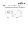
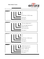
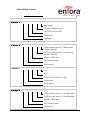
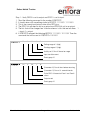
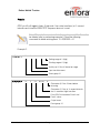
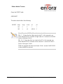
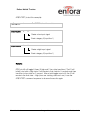
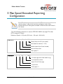
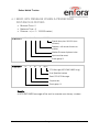
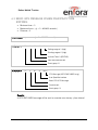
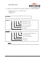
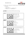
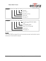
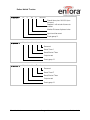
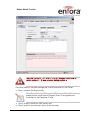
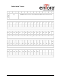
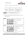
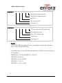
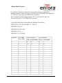
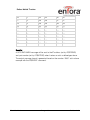
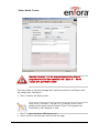
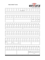
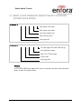
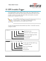
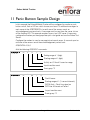
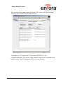
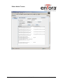
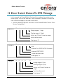
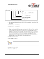
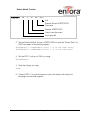
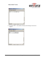
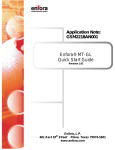
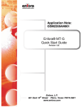
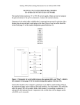
1
Enfora Mobile Tracker Event Cookbook GSM2000CB001 Revision: 1.02 11/13/2009 GENERAL TERMS OF USE OF NEW MATERIALS - PLEASE READ CAREFULLY From time to time, Enfora, in its sole discretion, may make available for download on its website (www.enfora.com), or may transmit via mail or email, updates or upgrades to, or new releases of, the firmware, software or documentation for its products (collectively, 'New Materials'). Use of such New Materials is subject to the terms and conditions set forth below, and may be subject to additional terms and conditions as set forth in Enfora's Technical Support Policy (posted on its website) and/or any written agreement between the user and Enfora. All New Materials are provided AS IS. Enfora makes no warranty or representation with respect to the merchantability, suitability, functionality, accuracy or completeness of any such New Materials. The user of such New Materials assumes all risk (known or unknown) of such use. Enfora reserves all rights in such New Materials. The user shall have only a revocable and limited license to use such New Materials in connection with the products for which they are intended. Distribution or modification of any New Materials without Enfora's consent is strictly prohibited. IN NO EVENT WILL ENFORA BE RESPONSIBLE FOR ANY INCIDENTAL, INDIRECT, CONSEQUENTIAL OR SPECIAL DAMAGES AS A RESULT OF THE USE OF ANY NEW MATERIALS. ENFORA'S MAXIMUM LIABILITY FOR ANY CLAIM BASED ON THE NEW MATERIALS SHALL NOT EXCEED FIFTY U.S. DOLLARS ($50). COPYRIGHT © 2009 Enfora, Inc. All rights reserved. Complying with all applicable copyright laws is the responsibility of the user. Without limiting the rights under copyright, no part of this document may be reproduced, stored in or introduced into a retrieval system, or transmitted in any form or by any means (electronic, mechanical, photocopying, recording or otherwise), or for any purpose, without the express written permission of Enfora, Inc. Enfora and the Enfora logo are either registered trademarks or trademarks of Enfora, Inc. in the United States. 251 Renner Pkwy Richardson, TX 75080 USA 972-633-4400 Phone: (972) 633-4400 Fax: (972) 633-4444 Email: [email protected] www.enfora.com Event Cookbook Page I Revision: 1.02 TABLE OF CONTENTS General 1 Copyright 1 Table of Contents 2 Table of Figures 3 1 Introduction 1 1.1 Objective 1 1.2 Supported devices 1 1.3 Equipment Needed 1 1.4 References 1 1.5 Procedures 2 2 Mobile Tracker Test Wiring Diagrams 3 3 Mobile Tracker LED Definitions 4 4 Pulse Event Configuration 9 5 Max Speed Exceeded Reporting Configuration 15 6 Time-Distance Reporting Configuration 20 6.1 Send GPS message when a predefined distance is moved. 21 6.2 Send GPS message when Maximum Time expires. 22 6.3 Send GPS message when Minimum Time expires. 23 6.4 Send GPS message when Time OR Distance has elapsed. 24 6.5 Send GPS message based on Time AND Distance. 26 6.6 Send GPS message based on Minimum Time AND Distance OR when Maximum Time has elapsed. 28 7 Geo-Fencing Configuration 35 7.1 Send a GPS message when the unit leaves geo-fence 1 36 8 Power Save Configuration 43 8.1 Entering Power Save Mode 43 8.2 Send a GPS message when the Enfora® Mobile Tracker exits power save mode 45 8.3 Send a GPS message when the MT-G enters power save mode 46 9 GPS Idle Trigger 47 Event Cookbook P a g e II Revision: 1.02 10 GPS Invisible Trigger 49 11 Panic Button Sample Design 51 12 Door Switch Detect To SMS Message 55 13 Events to Detect Primary Power Loss 58 14 Events Biased on GPIO 1 ($IOPULUP) 61 TABLE OF FIGURES Figure 1 Map of World Displaying Latitude and Longitude ............................................... 35 Document ID P a g e | 3 Version Enfora Mobile Tracker 1 Introduction 1.1 OBJECTIVE The intent of this document is to provide information that details the steps necessary to configure the Enfora® Mobile Tracker LED interface. 1.2 SUPPORTED DEVICES • • • • GSM2203 MT-G GSM2208 MT-G GSM2218 MT-GL GSM2238 MT-μL Note: Some features may not be available on some hardware or firmware revisions. Please consult the applicable hardware documentation and firmware release notes. 1.3 EQUIPMENT NEEDED In this example the requirements are: • • An Enfora® MT series modem A notebook or desktop computer with any version of Microsoft Windows that has the HyperTerminal communications program. If this hardware is not available, the user could use a DOS terminal emulation program or DUMB ASCII terminal. 1.4 REFERENCES • • • • • • • • GSM2208AN001 GSM2000PB002MAN GSM2218AN001 GSM2218PB001MAN GSM2000PB001MAN GSM0107PB001MAN GSM0000AN015 GSM0000AN016 Event Cookbook MT-G Quick Start Enfora® MT-G Hardware User Manual MT-GL Quick Start Guide Enfora® MT-GL Hardware User Manual Enfora® Mobile Tracker Software User Manual Enabler-IIG AT Command Set Event Monitor and Reporting Overview How to Send an SMS Message to an E-Mail Address Page 1 Revision: 1.02 Enfora Mobile Tracker 1.5 PROCEDURES Note: Please note that the following event commands are examples only. When implementing, use the command AT$EVENT? to query the event table and use the next sequential event group number. Failure to do so could potentially cause unpredictable results. Some of these examples require that communication is established with a remote server. Read and understand the appropriate Quick Start Guide for your device prior to attempting these examples. Always verify that the local serial connection session is actually established with the Enfora® Mobile Tracker modem. Event Cookbook Page 2 Revision: 1.02 Enfora Mobile Tracker 2 Mobile Tracker Test Wiring Diagrams The following diagrams detail additional wiring that will be required to validate some of these examples. Event Cookbook Page 3 Revision: 1.02 Enfora Mobile Tracker 3 Mobile Tracker LED Definitions There are a total of three LEDs on the Enfora® Mobile Trackers. • • The power LED reflects the state of the power supplied to the unit. The user cannot change the power LED functionality. The other two LEDs are user-configurable and can be changed from the factory default definitions. The following displays the factory default settings. • Power LED display: • Registration LED display (USR1): • LED ON when power line connected to the device LED OFF when the device is in low power mode or power is disconnected from the unit LED OFF when unit is not registered or not trying to register LED blinking when unit is trying to register with the network LED solid ON when GSM is connected GPS Fix LED display (USR2): LED OFF when a GPS fix has not been acquired LED solid ON when GPS fix has been acquired The LED’s on the Enfora® Mobile Trackers are controlled by the event processing capability provided in the AT command structure. The following AT command settings provide an example of the use of event processing to reflect registration and GPS statuses. This example uses the actual I/O line 6 (GPIO6 / USR1) for the Registration LED. The other user configurable LED uses I/O line 7 (GPIO7 / USR2). AT$EVENT= 1, 0, 27, 1, 1, GPS status ending value of 1 GPS status beginning value of 1 Monitor GPS Status Input transition event Event group 1 Event Cookbook Page 4 Revision: 1.02 Enfora Mobile Tracker AT$EVENT= 1, 3, 22, 0, 0, N/A N/A Set GPIO line #7 (USR2) to high Output event Event group 1 AT$EVENT= 2, 0, 27, 0, 0, GPS status ending value of 0 GPS status beginning value of 0 Monitor GPS Status Input transition event Event group 2 AT$EVENT= 2, 3, 14, 0, 0, N/A N/A Set GPIO line #7 (USR2) to low Output event Event group 2 AT$EVENT= 3, 0, 9, 2, 4, +CREG ending value of 4 +CREG starting value of 2 Monitor +CREG value Input transition event Event group 3 Event Cookbook Page 5 Revision: 1.02 Enfora Mobile Tracker AT$EVENT= 3, 3, 37, 1, 0, Flash forever Flash at ¼ second intervals Flash GPIO line #6 (USR1) Output event Event group 3 AT$EVENT= 4, 0, 9, 5, 5, +CREG ending value of 5 – Registered on network, Roaming +CREG starting value of 5 – Registered on network, Roaming Monitor +CREG value Input transition event Event group 4 AT$EVENT= 4, 3, 21, 0, 0, N/A N/A Set GPIO line #6 (USR1) to High Output event Event group 4 AT$EVENT= 5, 0, 9, 0, 0, +CREG ending value of 0 – Not Registered +CREG starting value of 0 – Not Registered Monitor +CREG value Input transition event Event group 5 Event Cookbook Page 6 Revision: 1.02 Enfora Mobile Tracker AT$EVENT= 5, 3, 13, 0, 0, N/A N/A Set GPIO line #6 (USR1) to Low Output event Event group 5 AT$EVENT= 6, 0, 9, 1, 1, +CREG ending value of 1 – Registered on home network +CREG starting value of 11 – Registered on home network Monitor +CREG value Input transition event Event group 6 AT$EVENT= 6, 3, 21, 0, 0, N/A N/A Set GPIO line #6 (USR1) to High Output event Event group 6 Query the EVENT table: AT$EVENT? The table should reflect the following: $EVENT: evgp Event Cookbook evtyp evcat p1 Page 7 p2 Revision: 1.02 Enfora Mobile Tracker 1A 1B 2A 2B 3A 3B 4A 4B 5A 5B 6A 6B 0 3 0 3 0 3 0 3 0 3 0 3 27 22 27 14 9 37 9 21 9 13 9 21 1 0 0 0 2 1 5 0 0 0 1 0 1 0 0 0 4 0 5 0 0 0 1 0 Results: GPIO pin #6 (USR1) should flash at ¼ second intervals until device is registered on home or roaming networks. Once registered, GPIO pin #6 (USR1) will go high. If registration status is lost, the I/O pin will flash. Event Cookbook Page 8 Revision: 1.02 Enfora Mobile Tracker 4 Pulse Event Configuration Note: In the following discussion, OFF equals a signal low (0 Vdc) state and ON equals a signal High state. The Enfora® MT product line contains detailed event processing capability via the AT command structure. The MT modem allows a user to toggle the GPIO line to an On/Off state. The I/O line can pulse in multiples of quarter second (250 ms) increments. The user can select ON time and OFF time (in multiple of 250 ms increments) as desired. Parameter 1 defines the flash pattern of the LED: The upper 16 bits (bits 16 – 31) are defined as OFF time while the lower 16 bits (bits 0 – 15) are defined as ON time. If the OFF time is not specified (set to 0), then ON time will be the same as OFF time. Parameter 2 defines the toggle count. A value of 0 for toggle count means the I/O will be toggled forever. A user can select the number of times the pattern is toggled starting from the current I/O state. The user can select the final state of the I/O line to be either same as the current state or opposite of the current state. To select the final state to be the same as current state, the toggle count should be set to an even number. To select the final state to be opposite of the current state, the toggle count should be set to an odd number. The following AT command settings provide an example of the use of event processing to toggle an output line based on an input event: Event Cookbook Page 9 Revision: 1.02 Enfora Mobile Tracker Step 1 - Verify GPIO3 is set to output and GPIO1 is set to input. 1. 2. 3. 4. 5. Send the following command to the modem AT$IOCFG? It should return with something similar to $IOCFG: 11111001 11111001 This is the current input/output state of the GPIO pins. The GPIO1 bit will need to set to an output and GPIO3 bit set to an output. The bits that will be changed are 1x0xxxxx where x is bits that are left alone. 1 = input, 0 = output. 6. If AT$IOCFG returned the following $IOCFG: 11111001 11111001 Then the command that will be sent is AT$IOCFG=11011001 AT$EVENT= 10, 0, 0, 1, 1, Ending range of 1 (high) Starting range of 1 (high) Activity on I/O line #1 based on range Input transition event Event group 10 AT$EVENT= 10, 3, 34, 1, 8, (Parameter 2) Pulse 8 times before returning (Parameter 1) Pulse at ¼ second intervals Pulse GPIO #3 based on Parm1 and Parm2 values Output event Event group 10 Event Cookbook P a g e 10 Revision: 1.02 Enfora Mobile Tracker Query the EVENT table: AT$EVENT? The table should reflect the following: $EVENT: evgp evtyp evcat p1 p2 10A 0 0 1 1 10B 3 34 1 8 AT$EVTEST (to test this example): Note: It is the transition from a 0 to a 1 that causes event 9 to fire. In order to perform the test again, both EVTEST commands need to be sent. AT$IOGP3= 0 AT$EVENT= 0, Set GPIO3 to be in Low state 0, Create a low input signal Event category 0 (Input line 1) AT$EVENT= 0, 1, Create a high input signal Event category 0 (Input line 1) Event Cookbook P a g e 11 Revision: 1.02 Enfora Mobile Tracker Results: GPIO pin #3 will toggle 8 times (4 high and 4 low state transitions) at ¼ second intervals each time the AT$EVTEST sequence above is issued. Note: If Example 1 was entered into the modem, event 10 will need to be deleted prior to performing example 2. Send the following command to delete existing event 10. AT$EVDEL=10 Example 2: AT$EVENT= 10, 0, 0, 1, 1, Ending range of 1 (high) Starting range of 1 (high) Activity on I/O line #1 based on range Input transition event Event group 10 AT$EVENT= 10, 3, 34, 65539, 8, (Parameter 2) Pulse 5 times before returning (Parameter 1) Pulse at ¼ second intervals and ¾ second at high transition Pulse GPIO #3 based on Parm1 and Parm2 values Output event Event group 10 Event Cookbook P a g e 12 Revision: 1.02 Enfora Mobile Tracker Query the EVENT table: AT$EVENT? The table should reflect the following: $EVENT: evgp evtyp evcat p1 p2 10A 0 0 1 1 10B 3 34 65539 5 Note: The value 65539 for Parm1 is derived as follows: Bits 0 – 15 describe the High state for the IO. In this example, we have selected the IO to remain in high state for ¾ seconds or 0x0003 (hex) as the lower 16 bits. Bits 16 – 31 describe the Low state for the IO. In this example, we have selected the IO to remain in low state for ¼ second or 0x0001 (hex) as the upper 16 bits. When we combine the upper and lower 16 bits, we get: 0x00010003 in hex or 65539 in decimal. Event Cookbook P a g e 13 Revision: 1.02 Enfora Mobile Tracker AT$EVTEST (to test this example): AT$IOGP3= 0 AT$EVTEST = 0, Set GPIO3 to be in Low state 0, Create a low input signal Event category 0 (Input line 1) AT$EVTEST = 0, 1, Create a high input signal Event category 0 (Input line 1) Results: GPIO pin #3 will toggle 5 times (3 high and 2 low state transitions). The IO will initially start with a High state. It will remain in that state for ¾ seconds and then transition to low state for ¼ second. After a total toggle count of 5, the IO will remain in the final state – High (since our starting state was Low). Issue the AT$EVTEST command sequence to observe the results again. Event Cookbook P a g e 14 Revision: 1.02 Enfora Mobile Tracker 5 Max Speed Exceeded Reporting Configuration Note: The following examples require the MT device to report to a remote server. If you do not have one configured, refer to the appropriate Quick Start guide to enable communication with Enfora’s test server. Type the following commands to send a GPS RMC NMEA message OTA when MT-G exceeds 30 Knots. Maximum Speed = 30 (knots) (30 Knots ≈ 35 mph ≈ 56 Km/Hr) AT$EVENT= 11, 0, 17, 30, 250, Should always be 250 (max speed) Max Speed to monitor (0 – 249) Monitor speed (Input Event Number) Input transition event Event group 11 AT$EVENT= 11, 3, 40, 7, 4350, OTA Message (ASCII RMC NMEA msg) User Specified number Send OTA UDP Message Output event Event group 11 Event Cookbook P a g e 15 Revision: 1.02 Enfora Mobile Tracker Results: Parameter 2 Decode is as follows: Param2 decode = 4350 Bit 00 > ASCII Bit 01 > PARAM1 11 bytes ASCII Bit 02 > MDMID added 22 bytes ASCII Bit 03 > GPIO 6 bytes ASCII Bit 04 > A/D1 5 bytes ASCII Bit 05 > A/D2 5 bytes ASCII Bit 06 > Store messages if out of GPRS coverage Bit 07 > Input Event Number 3 bytes ASCII Bit 08 > Bit 09 > Bit 10 > Bit 11 > Bit 12 > RMC NMEA Data max 80 bytes ASCII Bit 13 > Bit 14 > Bit 15 > Bit 16 > Bit 17 > Bit 18 > Bit 19 > Bit 20 > Bit 21 > A GPS RMC NMEA message will be sent to the IP address (set by AT$FRIEND) and port number (set by AT$UDPAPI) every time the device exceeds speed of 30 Knots. The MT modem has to go below the set speed of 30 Knots in order to trigger the event again. Event Cookbook P a g e 16 Revision: 1.02 Enfora Mobile Tracker The output message format is generated based on the number “4350” set in the second AT$EVENT command. Below is the example output that would be seen if the modem were setup to report to the Enfora test server. Described below is the data package that should be received by the server. • Row 1 indicates the Byte number. Note: Bytes 0 through 27 are part of IPV4 header. Bytes 28 and greater are the actual packet Payload. Bytes 32 and greater are controlled by the Parameter 2 value. • • Row 2 displays the data in HEX format, and Row 3 and/or 4 describe each block of the message. Event Cookbook P a g e 17 Revision: 1.02 Enfora Mobile Tracker Byte Byte Byte Byte Byte Byte Byte Byte Byte Byte Byte Byte Byte Byte Byte Byte 0 1 2 3 4 5 6 7 8 9 10 11 12 13 14 15 IP Header data IP Header Byte Byte Byte Byte Byte Byte Byte Byte Byte Byte Byte Byte Byte Byte Byte Byte 16 17 18 19 20 21 22 23 24 25 26 27 28 29 30 31 00 04 02 00 Stat us reser ved UDP Header data IP Header (contd…) UDP Header ASCII GPS data UDP-API Header Byte Byte Byte Byte Byte Byte Byte Byte Byte Byte Byte Byte Byte Byte Byte Byte 32 33 34 35 36 37 38 39 40 41 42 43 44 45 46 47 20 20 20 20 20 20 20 20 20 37 20 20 20 20 20 20 User Specified Number (7) Modem ID Byte Byte Byte Byte Byte Byte Byte Byte Byte Byte Byte Byte Byte Byte Byte Byte 48 49 50 51 52 53 54 55 56 57 58 59 60 61 62 63 20 20 20 20 20 20 20 20 20 4D 54 5F 54 65 73 74 Modem ID continued… (MT_Test) Byte Byte Byte Byte Byte Byte Byte Byte Byte Byte Byte Byte Byte Byte Byte Byte 64 65 66 67 68 69 70 71 72 73 74 75 76 77 78 79 20 66 39 2C 20 36 2C 20 31 37 34 38 20 31 37 34 Mod em ID cont Mask com ma Data spac e A/D 1 A/D 2 GPIO Byte Byte Byte Byte Byte Byte Byte Byte Byte Byte Byte Byte Byte Byte Byte 80 81 82 83 84 85 86 87 88 89 90 91 92 93 94 38 20 31 37 20 24 47 50 52 4D 43 2C 31 39 32 A/D 2 continued Event Cookbook Input Event Number (17) P a g e 18 Byte 95 35 ASCII NMEA RMC message ($GPRMC,192541.88,A,3301.5292,N, 09642.5675,W, 31.8,006.1,210704,05 ,E*53) Revision: 1.02 Enfora Mobile Tracker Byte Byte Byte Byte Byte Byte Byte Byte Byte Byte Byte Byte Byte Byte Byte Byte 111 96 97 98 99 100 101 102 103 104 105 106 107 108 109 110 34 31 2E 38 38 2C 41 2C 33 33 30 31 2E 35 32 39 Byte 127 ASCII NMEA RMC message continued… Byte Byte Byte Byte Byte Byte Byte Byte Byte Byte Byte Byte Byte Byte Byte 112 113 114 115 116 117 118 119 120 121 122 123 124 125 126 32 2C 4E 2C 30 39 36 34 32 2E 35 36 37 35 2C 57 Byte 143 ASCII NMEA RMC message continued… Byte Byte Byte Byte Byte Byte Byte Byte Byte Byte Byte Byte Byte Byte Byte 128 129 130 131 132 133 134 135 136 137 138 139 140 141 142 2C 33 31 2E 38 2C 30 30 36 2E 31 2C 32 31 30 37 ASCII NMEA RMC message continued… Byte Byte Byte Byte Byte Byte Byte Byte Byte Byte Byte Byte Byte 144 145 146 147 148 149 150 151 152 153 154 155 156 30 34 2C 30 35 2C 45 2A 35 33 0D 0A 00 ASCII NMEA RMC message continued… Event Cookbook P a g e 19 Revision: 1.02 Enfora Mobile Tracker 6 Time-Distance Reporting Configuration Type the following commands to send a GPS RMC NMEA message OTA to a remote Server when time and/or distance settings are violated. Users must use Event Timer 1 ($EVTIM1) for minimum time and Event Timer 2 ($EVTIM2) for maximum time when setting up for this feature. The time and/or distance feature is designed as described in the example table below: Minimum Maximum Distance Comments Time (secs) Time (secs) (meters) 0 0 0 Feature disabled 0 0 100 GPS message sent every 100 meters 0 60 0 GPS message sent every 60 seconds 0 60 100 GPS message sent every 60 seconds if the vehicle has not moved 100 meters. GPS messages will be sent every 100 meters if the vehicle is moving and traveling the distance of 100 meters in less than 60 seconds. In short, message is sent upon expiration of time or moving of distance – whichever occurs first. 30 x 0 GPS message sent every 30 seconds (x = don’t care) 30 0 100 GPS message sent when the vehicle has moved 100 meters and 30 seconds have elapsed. 30 60 100 GPS message sent every 60 seconds if the vehicle is idle and not moving or moving slowly. If the vehicle is moving, then GPS message will be sent when 30 seconds have expired and 100 meters have been moved. Warning: Choose only one option, from options 1 – 6 below. Before attempting another option delete the existing events by issuing the following commands: AT$EVDEL=12 AT$EVDEL=13 The following sections examples of the use of event processing to configure the Time and/or Distance feature. Event Cookbook P a g e 20 Revision: 1.02 Enfora Mobile Tracker 6.1 SEND GPS MESSAGE WHEN A PREDEFINED DISTANCE IS MOVED. • • • Minimum Time = 0 Maximum Time = 0 Distance = z (z = 0 – 1000000 meters) AT$EVENT= 12, 0, 16, z, 1000000, Should always be 1000000 (max distance) Replace z with actual distance to monitor Monitor Distance displaced value Input transition event Event group 12 AT$EVENT= 12, 3, 40, 8, 4350, OTA Message (ASCII RMC NMEA msg) User Specified number Send OTA UDP Message Output event Event group 12 Results: A GPS RMC NMEA message will be sent to a remote user at every z meters. Event Cookbook P a g e 21 Revision: 1.02 Enfora Mobile Tracker 6.2 SEND GPS MESSAGE WHEN MAXIMUM TIME EXPIRES. • • • Minimum time = 0 Maximum time = y (y = 0 – 604800 seconds) Distance = 0 AT$EVTIM2 = y AT$EVENT= 12, (y = 0 - 604800 seconds) 1, 13, 1, 1, Ending range of 1 (high) Starting range of 1 (high) Activate Timer 2 ($EVTIM2) Input occurrence event Event group 12 AT$EVENT= 12, 3, 40, 8, 4350, OTA Message (ASCII RMC NMEA msg) User Specified number Send OTA UDP Message Output event Event group 12 Results: A GPS RMC NMEA message will be sent to a remote user at every y time interval. Event Cookbook P a g e 22 Revision: 1.02 Enfora Mobile Tracker 6.3 SEND GPS MESSAGE WHEN MINIMUM TIME EXPIRES. • • • Minimum time = x (x = 0 – 604800 seconds) Maximum time = 0 Distance = 0 AT$EVTIM1 = x AT$EVENT= 12, (x = 0 - 604800 seconds) 1, 12, 1, 1, Ending range of 1 (high) Starting range of 1 (high) Activate Timer 2 ($EVTIM1) Input occurrence event Event group 12 AT$EVENT= 12, 3, 40, 8, 4350, OTA Message (ASCII RMC NMEA msg) User Specified number Send OTA UDP Message Output event Event group 12 Results: A GPS RMC NMEA message will be sent to a remote user at every x time interval. Event Cookbook P a g e 23 Revision: 1.02 Enfora Mobile Tracker 6.4 SEND GPS MESSAGE WHEN TIME OR DISTANCE HAS ELAPSED. • • • Minimum time = 0 Maximum time = y (y = 0 – 604800 seconds) Distance = z (z = 0 – 1000000 meters) AT$EVTIM2 = y AT$EVENT= 12, (y = 0 - 604800 seconds) 1, 13, 1, 1, Ending range of 1 (high) Starting range of 1 (high) Activate Timer 2 ($EVTIM2) Input occurrence event Event group 12 AT$EVENT= 12, 3, 43, 2, 0, Reserved Reset Timer 2 Reset/Restart Timer Output event Event group 12 AT$EVENT= 12, 3, 40, 8, 4350, OTA Message (ASCII RMC NMEA msg) User Specified number Send OTA UDP Message Output event Event group 12 Event Cookbook P a g e 24 Revision: 1.02 Enfora Mobile Tracker AT$EVENT= 13, 0, 16, z, 1000000, Should always be 1000000 (max distance) Replace z with actual distance to monitor Monitor Distance displaced value) Input transition event Event group 13 AT$EVENT= 13, 3, 43, 2, 0, Reserved Reset Timer 2 Reset/Restart Timer Output event Event group 13 AT$EVENT= 13, 3, 40, 9, 4350, OTA Message (ASCII RMC NMEA msg) User Specified number Send OTA UDP Message Output event Event group 13 Results: A GPS RMC NMEA message will be sent to a remote user every time the device travels z distance or y time interval has elapsed. Event Cookbook P a g e 25 Revision: 1.02 Enfora Mobile Tracker 6.5 SEND GPS MESSAGE BASED ON TIME AND DISTANCE. In this instance, a GPS message will not be sent to the remote user until the device travels specified distance and time has expired. • • • Minimum time = x (x = 0 – 604800 seconds) Maximum time = 0 Distance = z (z = 0 – 1000000 meters) AT$EVTIM1 = x AT$EVENT= 1 2, (x = 0 - 604800 seconds) 1, 12, 1, 1, Ending range of 1 (high) Starting range of 1 (high) Activate Timer 2 ($EVTIM1) Input occurrence event Event group 12 AT$EVENT= 1 2, 0, 16, z, 1000000, Should always be 1000000 (max distance) Replace z with actual distance to monitor Monitor Distance displaced value Input transition event Event group 12 Event Cookbook P a g e 26 Revision: 1.02 Enfora Mobile Tracker AT$EVENT= 1 2, 3, 4 3, 1, 0, Reserved Reset Timer 1 Reset/Restart Timer Output event Event group 12 AT$EVENT= 1 2, 3, 40, 8, 4350, OTA Message (ASCII RMC NMEA msg) User pecified number Send OTA UDP Message Output event Event group 12 Results: A GPS RMC NMEA message will be sent to a remote user every time the device travels z distance and x time interval has elapsed. Event Cookbook P a g e 27 Revision: 1.02 Enfora Mobile Tracker 6.6 SEND GPS MESSAGE BASED ON MINIMUM TIME AND DISTANCE OR WHEN MAXIMUM TIME HAS ELAPSED. In this instance, a GPS message will not be sent to the remote user until the device travels specified distance and minimum time has expired or distance has not been traveled and maximum time has expired. Note: Maximum Time has to be greater than Minimum Time • • • Minimum time = x (x = 0 – 604800 seconds) Maximum time = y (y = 0 – 604800 seconds) Distance = z (z = 0 – 1000000 meters) AT$EVTIM1 = x (x = 0 - 604800 seconds) AT$EVTIM2 = y (y = 0 - 604800 seconds) AT$EVENT= 12, 1, 12, 1, 1, Ending range of 1 (high) Starting range of 1 (high) Activate Timer 2 ($EVTIM1) Input occurrence event Event group 12 Event Cookbook P a g e 28 Revision: 1.02 Enfora Mobile Tracker AT$EVENT= 12, 0, 16, z, 1000000, Should always be 1000000 (max distance) Replace z with actual distance to monitor Monitor Distance displaced value Input transition event Event group 12 AT$EVENT= 12, 3, 43, 1, 0, Reserved Reset Timer 1 Reset/Restart Timer Output event Event group 12 AT$EVENT= 12, 3, 43, 2, 0, Reserved Reset Timer 2 Reset/Restart Timer Output event Event group 12 Event Cookbook P a g e 29 Revision: 1.02 Enfora Mobile Tracker AT$EVENT= 12, 3, 4 0, 8, 4350, OTA Message (ASCII RMC NMEA msg) User Specified number Send OTA UDP Message Output event Event group 12 AT$EVENT= 1 3, 1, 13, 1, 1, Ending range of 1 (high) Starting range of 1 (high) Activate Timer 2 ($EVTIM2) Input occurrence event Event group 13 AT$EVENT= 1 3, 3, 43, 1, 0, Reserved Reset Timer 1 Reset/Restart Timer Output event Event group 13 AT$EVENT= 1 3, 3, 43, 2, 0, Reserved Reset Timer 1 Reset/Restart Timer Output event Event group 13 Event Cookbook P a g e 30 Revision: 1.02 Enfora Mobile Tracker AT$EVENT= 1 3, 3, 4 0, 9, 4350, OTA Message (ASCII RMC NMEA msg) User Specified number Send OTA UDP Message Output event Event group 13 Results: A GPS RMC NMEA message will be sent to a remote user every time the device travels z distance and x time interval has elapsed OR y time interval has elapsed Results: A GPS RMC NMEA message will be sent to the IP address (set by AT$FRIEND) and port number (set by AT$UDPAPI). The output message format is generated based on the number “4350” set in section 6.1 above with the AT$EVENT command. The output message format is generated based on the number “4350” set in the second AT$EVENT command. Below is the example output that would be seen if the modem were setup to report to the Enfora test server based on example A-3. Event Cookbook P a g e 31 Revision: 1.02 Enfora Mobile Tracker Warning: Bytes 32 – 42 and 81 – 83 will change depending on which option (1 – 6) was selected during section a Described below is the data package that should be received by the Server. • Row 1 indicates the Byte number. Note: Bytes 0 through 27 are part of IPV4 header. Bytes 28 and greater are the actual packet Payload. Bytes 32 and greater are controlled by the Parameter 2 value. • • Row 2 displays the data in HEX format, and Row 3 and/or 4 describe each block of the message. Event Cookbook P a g e 32 Revision: 1.02 Enfora Mobile Tracker Byte Byte Byte Byte Byte Byte Byte Byte Byte Byte Byte Byte Byte Byte Byte Byte 0 1 2 3 4 5 6 7 8 9 10 11 12 13 14 15 IP Header data IP Header Byte Byte Byte Byte Byte Byte Byte Byte Byte Byte Byte Byte Byte Byte Byte Byte 16 17 18 19 20 21 22 23 24 25 26 27 28 29 30 31 00 04 02 00 Stat us rese rved UDP Header data IP Header (contd…) UDP Header ASCII GPS data UDP-API Header Byte Byte Byte Byte Byte Byte Byte Byte Byte Byte Byte Byte Byte Byte Byte Byte 32 33 34 35 36 37 38 39 40 41 42 43 44 45 46 47 20 20 20 20 20 20 20 20 20 38 20 20 20 20 20 20 User Specified Number (8) Modem ID Byte Byte Byte Byte Byte Byte Byte Byte Byte Byte Byte Byte Byte Byte Byte Byte 48 49 50 51 52 53 54 55 56 57 58 59 60 61 62 63 20 20 20 20 20 20 20 20 20 4d 54 5f 54 65 73 74 Byte 79 Modem ID continued… (MT_Test) Byte Byte Byte Byte Byte Byte Byte Byte Byte Byte Byte Byte Byte Byte Byte 64 65 66 67 68 69 70 71 72 73 74 75 76 77 78 20 66 39 2C 20 36 20 31 37 34 38 20 31 37 34 Mod em ID cont inue d Mask GPIO Byte Byte Byte Byte Byte Byte Byte Byte Byte Byte Byte Byte Byte Byte Byte 80 81 82 83 84 85 86 87 88 89 90 91 92 93 94 Event Cookbook com ma Data spa ce A/D 1 P a g e 33 38 A/D 2 Byte 95 Revision: 1.02 Enfora Mobile Tracker 20 31 32 20 24 47 50 52 4d 43 2c 31 39 35 33 34 A/D 2 cont inue d Input Event Number (12) ASCII NMEA RMC message Byte Byte Byte Byte Byte Byte Byte Byte Byte Byte Byte Byte Byte Byte Byte 96 97 98 99 100 101 102 103 104 105 106 107 108 109 110 37 2e 39 32 2c 41 2c 33 33 32 32 2e 37 32 38 34 Byte 127 ($GPRMC,195347.92,A,3322.7284,N,09624.6839,W,56.2,059.0,210704,04,E*5F) Byte 111 ASCII NMEA RMC message continued… Byte Byte Byte Byte Byte Byte Byte Byte Byte Byte Byte Byte Byte Byte Byte 112 113 114 115 116 117 118 119 120 121 122 123 124 125 126 2c 4e 2c 30 39 36 32 34 2e 36 38 33 39 2c 57 2c Byte 143 ASCII NMEA RMC message continued… Byte Byte Byte Byte Byte Byte Byte Byte Byte Byte Byte Byte Byte Byte Byte 128 129 130 131 132 133 134 135 136 137 138 139 140 141 142 35 36 2e 32 2c 30 35 39 2e 30 2c 32 31 30 37 30 ASCII NMEA RMC message continued… Byte Byte Byte Byte Byte Byte Byte Byte Byte Byte Byte 144 145 146 147 148 149 150 151 152 153 154 34 2c 30 34 2c 45 2a 35 46 0d 0a ASCII NMEA RMC message continued… Event Cookbook P a g e 34 Revision: 1.02 Enfora Mobile Tracker 7 Geo-Fencing Configuration The Enfora® Mobile Tracker allows a user to configure maximum of 25 circular shape geo-fences. Enfora® Mobile Trackers can be configured to send GPS messages to a remote user (server) whenever a device enters or exits a geo-fenced area. The geo-fence feature has to be configured with two commands: AT$GEOFNC and AT$EVENT. To configure sending messages when a device enters or exits the geo fenced area, follow the example below: • • • • • • • • NMEA messages provide Latitude and Longitude information in “Degrees Minute.Minute” format. To obtain the decimal value for Degrees, take Minute.Minute of the actual Latitude or Longitude and divide it by 60. Latitude value should be between –90.0 to +90.0 Degrees Longitude value should be between –180.0 to +180.0 Degrees. Latitude North of Equator line should always be positive Value. Latitude South of the Equator line should always be negative value. Longitude East of the GMT line should always be positive. Longitude West of the GMT line should always be negative North GMT Equator East West South Figure 1 Map of World Displaying Latitude and Longitude Ex: Send a NMEA RMC GPS message when the Mobile Tracker moves in/out of the geo-fence area 1. Geo fence 1 is a 100 meter radius from the center point defined by Latitude = 33 01.5023 (North) and Longitude = 096 42.3853 (West). According to figure 6 above, Latitude of 33 01.5023 (North) would be a positive value (since its above the Equator line) but Longitude of 96 42.3853 (West) would be a negative value since it is west of the GMT line. Event Cookbook P a g e 35 Revision: 1.02 Enfora Mobile Tracker Verify each AT command sent to the modem returns OK. Radius: 100 meters Latitude: 33 01.5023 North = 33 + 01.5023/60 = 33.02503833 Longitude: 096 42.3853 West = -96 + 42.3853/60 = -96.70642167 AT$GEOFNC= 1,100,33.02503833,-96.70642167 7.1 SEND A GPS MESSAGE WHEN THE UNIT LEAVES GEO-FENCE 1 AT$EVENT= 14, 0, 21, 0, 0, Transition OUT of geo-fence area Transition OUT of geo-fence area Geo-Fence 1 Input transition event Event group 14 AT$EVENT= 14, 3, 40, 14, 4350, OTA Message (ASCII RMC NMEA msg) User Specified number Send OTA UDP Message Output event Event group 14 Send a GPS message when the unit enters geo-fence 1 Event Cookbook P a g e 36 Revision: 1.02 Enfora Mobile Tracker AT$EVENT= 15, 0, 21, 1, 1, Transition IN the geo-fence area Transition IN the geo-fence area Geo-Fence 1 Input transition event Event group 15 AT$EVENT= 15, 3, 40, 15, 4350, OTA Message (ASCII RMC NMEA msg) User Specified number Send OTA UDP Message Output event Event group 15 Results: A GPS RMC NMEA message will be sent to a remote user every time the device enters or exits the geo fence area. To add Geo-Fence 2, send the following commands to the MT-G and verify that an OK is returned. AT$GEOFNC=2,100,34.02503833,-97.70642167 AT$EVENT=16,0,22,0,0 AT$EVENT=16,3,40,16,4350 AT$EVENT=17,0,22,1,1 AT$EVENT=17,3,40,17,4350 Event Cookbook P a g e 37 Revision: 1.02 Enfora Mobile Tracker For additional Geofences, repeat the 5 commands below by changing the GeoFence (index) number (A), radius (100), latitude (34.02503833), and longitude (97.70642167) information for AT$GEOFNC command. And, increment the Event group numbers (B, C), Input Event (D), and User Specified Number (E, F) for AT$EVENT command. Use the following table for the relationship between the numbers AT$GEOFNC=A,100,34.02503833,-97.70642167 AT$EVENT=B,0,D,0,0 AT$EVENT=B,3,40,E,4350 AT$EVENT=C,0,D,1,1 AT$EVENT=C,3,40,F,4350 GeoFence Input Trigger Event number Leave GeoFence Enter GeoFence Event User Number Event User Number A D B E C F 1 21 14 14 15 15 2 22 16 16 17 17 3 23 18 18 19 19 4 24 20 20 21 21 5 25 22 22 23 23 6 31 24 24 25 25 7 32 26 26 27 27 8 33 28 28 29 29 9 34 30 30 31 31 10 35 32 32 33 33 11 36 34 34 35 35 12 37 36 36 37 37 13 38 38 38 39 39 14 39 40 40 41 41 15 40 42 42 43 43 Event Cookbook P a g e 38 Revision: 1.02 Enfora Mobile Tracker 16 41 44 44 45 45 17 42 46 46 47 47 18 43 48 48 49 49 19 44 50 50 51 51 20 45 52 52 53 53 21 46 54 54 55 55 22 47 56 56 57 57 23 48 58 58 59 59 24 49 60 60 61 61 25 50 62 62 63 63 Results: A GPS RMC NMEA message will be sent to the IP address (set by AT$FRIEND) and port number (set by AT$UDPAPI) when it enters or exits a defined geo fence. The output message format is generated based on the number “4350” set in above example with the AT$EVENT command. Event Cookbook P a g e 39 Revision: 1.02 Enfora Mobile Tracker Warning: Bytes 32 – 42 will change depending on what is programmed in the “user specified field”. Bytes 81 – 83 will change with geo-fence number Described below is the data package that should be received by the Server when the modem exits GeoFence 1. • Row 1 indicates the Byte number. Note: Bytes 0 through 27 are part of IPV4 header. Bytes 28 and greater are the actual packet Payload. Bytes 32 and greater are controlled by the Parameter 2 value. • • Row 2 displays the data in HEX format, and Row 3 and/or 4 describe each block of the message. Event Cookbook P a g e 40 Revision: 1.02 Enfora Mobile Tracker Byte Byte Byte Byte Byte Byte Byte Byte Byte Byte Byte Byte Byte Byte Byte Byte 0 1 2 3 4 5 6 7 8 9 10 11 12 13 14 15 IP Header data IP Header Byte Byte Byte Byte Byte Byte Byte Byte Byte Byte Byte Byte Byte Byte Byte Byte 16 17 18 19 20 21 22 23 24 25 26 27 28 29 30 31 00 04 02 00 Stat us rese rved UDP Header data IP Header (contd…) UDP Header ASCII GPS data UDP-API Header Byte Byte Byte Byte Byte Byte Byte Byte Byte Byte Byte Byte Byte Byte Byte Byte 32 33 34 35 36 37 38 39 40 41 42 43 44 45 46 47 20 20 20 20 20 20 20 20 31 34 20 20 20 20 20 20 User Specified Number (14) Modem ID Byte Byte Byte Byte Byte Byte Byte Byte Byte Byte Byte Byte Byte Byte Byte Byte 48 49 50 51 52 53 54 55 56 57 58 59 60 61 62 63 20 20 20 20 20 20 20 20 20 4d 54 5f 54 65 73 74 Byte 79 Modem ID continued… (MT_Test) Byte Byte Byte Byte Byte Byte Byte Byte Byte Byte Byte Byte Byte Byte Byte 64 65 66 67 68 69 70 71 72 73 74 75 76 77 78 20 66 39 2C 20 36 20 31 37 34 38 20 31 37 34 Mod em ID cont. Mask com ma Data spa ce A/D 1 38 A/D 2 GPIO Byte Byte Byte Byte Byte Byte Byte Byte Byte Byte Byte Byte Byte Byte Byte 80 81 82 83 84 85 86 87 88 89 90 91 92 93 94 20 32 31 20 24 47 50 52 4d 43 2c 31 39 32 35 A/D 2 continued Input Event Number (21) Byte 95 32 ASCII NMEA RMC message ($GPRMC,192527.88,A,3301.4850,N ,09642.5504,W,21.1,269.8,210704,0 5,E*59) Event Cookbook P a g e 41 Revision: 1.02 Enfora Mobile Tracker Byte Byte Byte Byte Byte Byte Byte Byte Byte Byte Byte Byte Byte Byte Byte Byte 111 96 97 98 99 100 101 102 103 104 105 106 107 108 109 110 37 2e 38 38 2c 41 2c 33 33 30 31 2e 34 38 35 30 Byte 127 ASCII NMEA RMC message continued… Byte Byte Byte Byte Byte Byte Byte Byte Byte Byte Byte Byte Byte Byte Byte 112 113 114 115 116 117 118 119 120 121 122 123 124 125 126 2c 4e 2c 30 39 36 34 32 2e 35 35 30 34 2c 57 2c Byte 143 ASCII NMEA RMC message continued… Byte Byte Byte Byte Byte Byte Byte Byte Byte Byte Byte Byte Byte Byte Byte 128 129 130 131 132 133 134 135 136 137 138 139 140 141 142 32 31 2e 31 2c 32 36 39 2e 38 2c 32 31 30 37 30 ASCII NMEA RMC message continued… Byte Byte Byte Byte Byte Byte Byte Byte Byte Byte Byte 144 145 146 147 148 149 150 151 152 153 154 34 2c 30 35 2c 45 2a 35 39 0d 0a ASCII NMEA RMC message continued… Event Cookbook P a g e 42 Revision: 1.02 Enfora Mobile Tracker 8 Power Save Configuration Enfora® Mobile Trackers allow a user to configure the device to enter or exit low power mode based on Ignition and/or DTR setting. The Enfora® Mobile Tracker has to be configured via AT commands as well as the hardware has to be wired accordingly to enter low power mode. 8.1 ENTERING POWER SAVE MODE Select one of the options from 1 thru 6 below for your desired method to enter low power mode. Note: The MT-Gμ does not have a DTR input. Examples 4,5,6 do not apply to the MT-Gμ. If you are using these examples for MT-Gu, there are only three parameters available (i.e. AT$PWRSAV=<IGNITION>,<TIMEOUT>,<REG>). Please review GSM2338AT001 for correct syntax. MT-GL/MT-μL require 4 parameters: (i.e. AT$PWRSAV=<DTR>,<IGNITION>,<TIMEOUT>,<REG>) Note: Example 3 only needs to be used if the MT-G does not automatically reset when Ignition source is applied. Note: Do not use a delay time of 0 if you are planning to include GPS messages. 1. Enter the following command to put the MT in Low Power Mode immediately when Ignition is turned OFF. The MT should respond back with OK. AT$PWRSAV=0,1,1,0 Event Cookbook P a g e 43 Revision: 1.02 Enfora Mobile Tracker 2. Enter the following command to put the MT in Low Power Mode 10 seconds after the Ignition has been turned OFF. The MT should respond back with OK. AT$PWRSAV=0,1,10,0 3. Enter the following command to reset the MT when Ignition is turned ON after being in low power mode during Ignition Off. The MT should respond back with OK. AT$PWRSAV=0,1,10,1 4. Enter the following command to put the MT-G in Low Power Mode immediately when DTR is disconnected. The MT-G should respond back with OK. AT$PWRSAV=1,0,1,0 5. Enter the following command to put the MT-G in Low Power Mode immediately when DTR is disconnected. When DTR is connected, the MT-G will reset. The MT-G should respond back with OK. AT$PWRSAV=1,0,1,1 6. Enter the following command to put the MT-G in Low Power Mode 10 seconds after DTR is disconnected and Ignition is turned OFF. The MT-G should respond back with OK. AT$PWRSAV=1,1,10,0 Note: In Low Power Mode, the GPS receiver is turned OFF and hence one would not get any GPS data through the serial port or OTA. However, the modem is still registered and connected to the GSM/GPRS network. A user can also select to get notified when the Enfora® Mobile Tracker enters low power mode or exits Low Power Mode. Use the following AT commands to configure sending of message when the MT enters or exits low power mode. Event Cookbook P a g e 44 Revision: 1.02 Enfora Mobile Tracker 8.2 SEND A GPS MESSAGE WHEN THE ENFORA® MOBILE TRACKER EXITS POWER SAVE MODE AT$EVENT= 64, 0, 26, 0, 0, Exit power save mode Exit power save mode Low Power Mode Event Input transition event Event group 64 AT$EVENT= 64, 3, 40, 64, 4350, OTA Message (ASCII RMC NMEA msg) User Specified number Send OTA UDP Message Output event Event group 64 Event Cookbook P a g e 45 Revision: 1.02 Enfora Mobile Tracker 8.3 SEND A GPS MESSAGE WHEN THE MT-G ENTERS POWER SAVE MODE AT$EVENT= 65, 0, 26, 1, 1, Enter power save mode Enter power save mode Low Power Mode Event Input transition event Event group 65 AT$EVENT= 65, 3, 40, 65, 4350, OTA Message (ASCII RMC NMEA msg) User Specified number Send OTA UDP Message Output event Event group 65 Results: A GPS RMC NMEA message will be sent to a remote user every time the device enters or exits low power mode. Event Cookbook P a g e 46 Revision: 1.02 Enfora Mobile Tracker 9 GPS Idle Trigger The Enfora® Mobile Tracker maintains GPS Idle count. The Idle count is incremented every second that the unit has not moved and is stationary in one position. The user can elect to receive a GPS message when the Idle count exceeds. Idle count is measured in seconds. Note: A GPS Idle Trigger message will only be sent once when the timer expires. The message will not be repeated if the device/vehicle has not moved. To send a GPS message when the device/vehicle stays idle for 2 minutes (120 seconds), configure as follows: AT$EVENT= 68, 0, 30, 120, 1000000, Max timeout value Idle time in seconds (120 seconds) GPS Idle Trigger Input Event Input transition event Event group 68 AT$EVENT= 6 8, 3, 40, 6 8, 4350, OTA Message (ASCII RMC NMEA msg) User Specified number Send OTA UDP Message Output event Event group 68 Event Cookbook P a g e 47 Revision: 1.02 Enfora Mobile Tracker Query the EVENT table: AT$EVENT? The table should reflect the following: $EVENT: evgp Event Cookbook evtyp evcat p1 p2 68A 0 30 120 1000000 68 3 40 68 4350 P a g e 48 Revision: 1.02 Enfora Mobile Tracker 10 GPS Invisible Trigger The Enfora® Mobile Tracker maintains GPS Invisible count. The Invisible count is incremented every second when the unit does not have valid GPS data. The user can elect to receive a message when the Invisible count exceeds a set period. Invisible count is measured in seconds. Note: A GPS Invisible Trigger message will only be sent once when the timer expires. The message will not be repeated if the device/vehicle has not acquired valid GPS data. To send a message when the device/vehicle stays idle for 1 minute (60 seconds), configure as follows: AT$EVENT= 6 9, 0, 29, 60, 1000000, Max timeout value Idle time in seconds (60 seconds) GPS Invisible Trigger Input Event Input transition event Event group 69 AT$EVENT= 6 9, 3, 40, 6 9, 4350, OTA Message (ASCII RMC NMEA msg) User Specified number Send OTA UDP Message Output event Event group 69 Event Cookbook P a g e 49 Revision: 1.02 Enfora Mobile Tracker Query the EVENT table: AT$EVENT? The table should reflect the following: $EVENT: evgp Event Cookbook evtyp evcat p1 p2 69A 0 29 60 1000000 698 3 40 69 4350 P a g e 50 Revision: 1.02 Enfora Mobile Tracker 11 Panic Button Sample Design In this example the Enfora® Mobile Tracker will be configured to monitor a push button switch, flash a LED on switch closure, and send 10 additional messages to each server in the AT$FRIENDS list or until one of the servers sends an acknowledgment response back. A message must be sent from the server to turn off the flashing LED. This example requires access to a UDP server. If necessary, configure the modem per the appropriate quick start guide and use the Enfora Test Server. Configure the modem to send a message twice to each server, 5 seconds apart or until one of the servers sends the acknowledgement packet back. AT$ACKTM=10,5,0 Add the following AT$EVENT commands. AT$EVENT= 72, 0, 0, 1, 1, Ending range of 1 (high) Starting range of 1 (high) Activity on I/O line #1 based on range Input transition event Event group 72 AT$EVENT= 72, 3, 34, 1, 0, Flash Forever Starting range of 1 (¼ second intervals) GPIO3 flash – Flash Line signal on GPIO line #3 based on Param1 Output transition event Event group 72 Event Cookbook P a g e 51 Revision: 1.02 Enfora Mobile Tracker AT$EVENT= 73, 3, 41, 911, 4102, OTA Message (ASCII RMC NMEA msg) User Specified number Send OTA UDP Message Output event Event group 72 Press the “Panic” button on the Enfora® Mobile Tracker. The LED attached to GPIO 3 will begin to flash at ¼ second intervals. Also the Enfora® Mobile Tracker will start sending UDP messages as programmed in step 2. Event Cookbook P a g e 52 Revision: 1.02 Enfora Mobile Tracker After a couple of messages, enable the “Auto ACK” button. One more message should be sent and then the messages will stop. To extinguish to LED type in the AT Command AT$IOGP3=0 in the “Command/Data box. Click on the “Write” button to send the AT command to the Mobile Tracker. The LED attached to GPIO 3 will stop flashing. Event Cookbook P a g e 53 Revision: 1.02 Enfora Mobile Tracker Event Cookbook P a g e 54 Revision: 1.02 Enfora Mobile Tracker 12 Door Switch Detect To SMS Message In this example the Enfora® Mobile Tracker will be configured to monitor a push button switch, such as the “door ajar” switch mounted on a vehicle, to inform the user via SMS messages on the state of the switch. 1. Add the following AT$EVENT commands to the Enfora® Mobile Tracker “Stock Factory Configuration.” AT$EVENT= 73, 0, 0, 1, 1, Ending range of 1 (high) Starting range of 1 (high) Activity on I/O line #1 based on range Input transition event Event group 73 AT$EVENT= 73, 3, 4 4, 1, 0, N/A Execute First AT$STOATEV Command Execute AT$STOATEV Output transition event Event group 73 AT$EVENT= 74, 0, 0, 0, 0, Ending range of 0 (low) Starting range of 0 (low) Activity on I/O line #1 based on range Input transition event Event group 74 Event Cookbook P a g e 55 Revision: 1.02 Enfora Mobile Tracker AT$EVENT= 74, 3, 4 4, 2, 0, N/A Execute Second AT$STOATEV Command Execute AT$STOATEV Output transition event Event group 74 2. Set the Enfora® Mobile Tracker’s AT$STOATEV to send the “Door State” SMS messages. AT$STOATEV=1, AT+CMSS=1 AT$STOATEV=2, AT+CMSS=2 3. Create the following SMS messages and save to the SIM card. Note: delete all SMS messages from the SIM card or take note of what message number is assigned to the stored SMS message. Then adjust AT$STOATEV accordingly. You can use a telephone number that can receive SMS messages such as a GSM cell phone or you can substitute the carrier’s email gateway for the telephone number. See application note: GSM0000AN016 “How to Send an SMS Message to an E-Mail Address” for more information. AT+CMGW=”5555551212” > Door Closed <CTRL-Z> Note:This is message #1 as stored in the SIM Card. AT+CMGW=”5555551212” > Door Open <CTRL-Z> Event Cookbook P a g e 56 Revision: 1.02 Enfora Mobile Tracker Note: This is message #2 as stored in the SIM Card. 4. Save the settings by using: AT&W 5. Reset the Modem and allow it to attach to the GSM/GPRS Network. 6. When the switch is pushed on the modem, it will send the SMS message stored in AT$STOATEV=2. When the switch is released the SMS message stored in AT$STOATEV=1. Event Cookbook P a g e 57 Revision: 1.02 Enfora Mobile Tracker 13 Events to Detect Primary Power Loss In this example the Enfora® MT-μL (GSM2238-00) will be configured to monitor and display to the terminal program, what power source it is currently running from. 1. Add the following AT$EVENT commands to the Enfora® Mobile Tracker “Stock Factory Configuration.” AT$EVENT= 90, 0, 3, 1, 1, Ending range of 1 (high) Starting range of 1 (high) Activity on I/O line #4 based on range Input transition event Event group 90 AT$EVENT= 90, 3, 44, 1, 0, N/A Execute First AT$STOATEV Command Execute AT$STOATEV Output transition event Event group 90 AT$EVENT= 91, 0, 3, 0, 0, Ending range of 0 (low) Starting range of 0 (low) Activity on I/O line #4 based on range Input transition event Event group 91 Event Cookbook P a g e 58 Revision: 1.02 Enfora Mobile Tracker AT$EVENT= 91, 3, 44, 2, 0, N/A Execute Second AT$STOATEV Command Execute AT$STOATEV Output transition event Event group 91 2. Set the Enfora® Mobile Tracker’s AT$STOATEV to send the “Power State” via ASCII messages to the terminal program. AT$STOATEV=1, AT$MSGSND=0,”Running on external power” AT$STOATEV=2, AT$MSGSND=0,”Running on internal battery” 3. Save the settings by using: AT&W 4. Turn the primary power supply OFF, the following message will be displayed from the Mobile Tracker. Event Cookbook P a g e 59 Revision: 1.02 Enfora Mobile Tracker 5. Turn the primary power supply ON; the following message will be displayed from the Mobile Tracker. Event Cookbook P a g e 60 Revision: 1.02 Enfora Mobile Tracker 14 Events Biased on GPIO 1 ($IOPULUP) In this example the Enfora® MT-μL (GSM2238-00 or -01) will be configured to monitor and display to the terminal program, the logic state of GPIO 1. 1. Add the following AT$EVENT commands to the Enfora® Mobile Tracker “Stock Factory Configuration.” AT$EVENT= 82, 0, 0, 1, 1, Ending range of 1 (high) Starting range of 1 (high) Activity on I/O line #4 based on range Input transition event Event group 92 AT$EVENT= 92, 3, 44, 1, 0, N/A Execute First AT$STOATEV Command Execute AT$STOATEV Output transition event Event group 92 AT$EVENT= 93, 0, 0, 0, 0, Ending range of 0 (low) Starting range of 0 (low) Activity on I/O line #4 based on range Input transition event Event group 93 Event Cookbook P a g e 61 Revision: 1.02 Enfora Mobile Tracker AT$EVENT= 6 8, 3, 40, 6 8, 4350, N/A Execute Second AT$STOATEV Command Execute AT$STOATEV Output transition event Event group 93 2. Set the Enfora® Mobile Tracker’s AT$STOATEV to send the “Power State” via ASCII messages to the terminal program. AT$STOATEV=1, AT$MSGSND=0,”GPIO 1 is in the HIGH State” AT$STOATEV=2, AT$MSGSND=0,”GPIO 1 is in the LOW State” 3. Set the GPIO 1 pull-up to LOW by issuing: AT$IOPULUP=0 4. Save the settings by using: AT&W 5. Connect GPIO 1 to a positive power source; the modem will display the following in the terminal program. Event Cookbook P a g e 62 Revision: 1.02 Enfora Mobile Tracker 6. Disconnect GPIO 1; the modem will display the following in the terminal program. Event Cookbook P a g e 63 Revision: 1.02