1
SwitchX Evaluation Board Hardware User Manual PN: MT51336-EN-EVB, MT51336-VPI-EVB Rev 1.0 www.mellanox.com NOTE: THIS HARDWARE, SOFTWARE OR TEST SUITE PRODUCT (“PRODUCT(S)”) AND ITS RELATED DOCUMENTATION ARE PROVIDED BY MELLANOX TECHNOLOGIES “AS-IS” WITH ALL FAULTS OF ANY KIND AND SOLELY FOR THE PURPOSE OF AIDING THE CUSTOMER IN TESTING APPLICATIONS THAT USE THE PRODUCTS IN DESIGNATED SOLUTIONS. THE CUSTOMER'S MANUFACTURING TEST ENVIRONMENT HAS NOT MET THE STANDARDS SET BY MELLANOX TECHNOLOGIES TO FULLY QUALIFY THE PRODUCTO(S) AND/OR THE SYSTEM USING IT. THEREFORE, MELLANOX TECHNOLOGIES CANNOT AND DOES NOT GUARANTEE OR WARRANT THAT THE PRODUCTS WILL OPERATE WITH THE HIGHEST QUALITY. ANY EXPRESS OR IMPLIED WARRANTIES, INCLUDING, BUT NOT LIMITED TO, THE IMPLIED WARRANTIES OF MERCHANTABILITY, FITNESS FOR A PARTICULAR PURPOSE AND NONINFRINGEMENT ARE DISCLAIMED. IN NO EVENT SHALL MELLANOX BE LIABLE TO CUSTOMER OR ANY THIRD PARTIES FOR ANY DIRECT, INDIRECT, SPECIAL, EXEMPLARY, OR CONSEQUENTIAL DAMAGES OF ANY KIND (INCLUDING, BUT NOT LIMITED TO, PAYMENT FOR PROCUREMENT OF SUBSTITUTE GOODS OR SERVICES; LOSS OF USE, DATA, OR PROFITS; OR BUSINESS INTERRUPTION) HOWEVER CAUSED AND ON ANY THEORY OF LIABILITY, WHETHER IN CONTRACT, STRICT LIABILITY, OR TORT (INCLUDING NEGLIGENCE OR OTHERWISE) ARISING IN ANY WAY FROM THE USE OF THE PRODUCT(S) AND RELATED DOCUMENTATION EVEN IF ADVISED OF THE POSSIBILITY OF SUCH DAMAGE. Mellanox Technologies 350 Oakmead Parkway Suite 100 Sunnyvale, CA 94085 U.S.A. www.mellanox.com Tel: (408) 970-3400 Fax: (408) 970-3403 Mellanox Technologies, Ltd. PO Box 586 Hermon Building Yokneam 20692 Israel Tel: +972-4-909-7200 Fax: +972-4-959-3245 © Copyright 2011. Mellanox Technologies. All rights reserved. Mellanox®, BridgeX®, ConnectX®, CORE-Direct®, InfiniBridge®, InfiniHost®, InfiniScale®, PhyX®, Virtual Protocol Interconnect and Voltaire are registered trademarks of Mellanox Technologies, Ltd. FabricIT, MLNX-OS and SwitchX are trademarks of Mellanox Technologies, Ltd. All other trademarks are property of their respective owners. SwitchX Switch EVB Hardware User Manual 2 Mellanox Technologies Document Number: 3493 SwitchX Switch EVB Hardware User Manual Rev 1.0 Table of Contents Revision Overview 9 Chapter 2 40 Gb/s Ethernet Chapter 3 FDR Chapter 4 Basic Operation and Installation yD 1.1 Management CPU 1.2 PCIE/1GbE Extender Kit 1.2.1 PCIE Extender Kit 1.2.2 1GbE Extender Kit 1.3 Compliance Ports 1.4 Reference Traces 1.5 Features 1.6 Serial Number and Product Version Information 15 16 38 5.1 5.2 5.3 5.4 5.5 5.6 5.7 5.8 5.9 5.10 38 40 42 43 45 46 49 49 50 50 ar Installing the PCIE/1GbE Server Side board in Chapter 7 14 16 17 22 23 23 23 23 24 26 26 28 29 29 33 34 34 36 36 im Chapter 6 9 10 10 10 11 11 12 13 4.1 Switch Platform Hardware Overview 4.1.1 Status LEDs 4.1.2 Reset Button 4.2 QSFP Cable Power Budget Classification 4.3 SFP+ Cable Power Budget Classification 4.4 Interfaces 4.4.1 Port Connector Interfaces 4.4.2 Management and Firmware Updating Interfaces 4.5 Switch Platform Installation and Operation 4.5.1 Installation Safety Warnings 4.5.2 Mechanical Installation 4.6 Package Contents and Installation 4.6.1 Installing the Switch in the Rack 4.6.2 Grounding the Switch 4.6.3 Power Connections and Initial Power On 4.6.4 Extracting and Inserting the Power Supply Unit 4.6.5 Cable Installation 4.6.6 Extracting and Inserting the Fan Unit Pr el Chapter 5 ra ft Chapter 1 8 PCIE/1GbE Extender Kit parts Removing the Top Cover Removing the Management CPU Installing the PCIE/1GbE Extender Installing the Server Side Board Board Connectors Numbering and Locations Switch Shut Down Procedure Disassembly of the Switch from the Rack Disposal Resetting the Switch Management and Tools Overview 51 6.1 Chassis Management Using the MLNX-OS Stack 6.2 Network Management and Clustering Software 6.3 Chassis Management 6.3.1 Open SM 6.4 Fabric Management with UFM 6.5 Configuring the Switch for the First Time 51 51 52 52 53 54 Connecting to the Switch Platform 60 Mellanox Technologies 3 Rev 1.0 60 60 62 62 62 63 Troubleshooting 64 Pr el im in ar yD ra ft Chapter 8 7.1 Starting an SSH Connection to the Switch (CLI) 7.2 Starting a WebUI Connection to the Switch 7.2.1 Managing the System 7.2.2 I2C Connector 7.2.3 How to Get Mellanox Firmware Tools (MFT) 7.3 Updating Firmware 4 Mellanox Technologies SwitchX Switch EVB Hardware User Manual Rev 1.0 List of Figures Connector and Power Side Panels 9 Figure 2: Pull Out Tab 13 Figure 3: Connector and Power Side Panel 16 Figure 4: Power Side Panel 16 Figure 5: Power, Fan, and System LEDs 18 Figure 6: System Health LED Figure 7: Power Side Panel Figure 8: PSU Status LEDs Figure 9: Fan Status LED Connector Side yD ra ft Figure 1: Figure 10: Fan Status LED Power side ar Figure 11: Reset Button Figure 13: Top and Bottom Ports Figure 15: Rack Rail Kit Parts Figure 16: Mounting Options im Figure 14: Management Interfaces in Figure 12: Port Numbering 18 19 20 20 21 22 23 24 24 30 31 32 Figure 18: Inserting the Caged Nuts 32 Figure 19: Slide the Rail into the Rail Slide 33 Figure 20: Power Supply Unit Extraction 35 Figure 21: PSU Pulled Out 35 Figure 22: Top and Bottom Ports 36 Figure 23: Air Flow Labels 37 Figure 24: Fan Module Latches 37 Figure 25: Server Side Card 39 Figure 26: PCIE/1GbE Extender 40 Figure 27: Screw Locations 41 Figure 28: Slide the Top 41 Figure 29: Management Board Installed 42 Figure 30: Unscrew the Management Board 42 Figure 31: Remove the Management Board 43 Figure 32: Holes for the Extender Board Interfaces 43 Figure 33: Install the Extender Board 44 Figure 34: Connecting the EVB to the Server Side Board 45 Figure 35: EVB Board Connections View 1 46 Pr el Figure 17: Screwing on the Rail Mellanox Technologies 5 Rev 1.0 50 Figure 37: Management Interfaces 54 Figure 38: Transfer Power Cord 71 Figure 39: Install the Power Cord Clip 72 Figure 40: Transfer Power Cord Finished 72 Figure 41: Connector Pinout 73 Pr el im in ar yD ra ft Figure 36: Reset Button 6 Mellanox Technologies SwitchX Switch EVB Hardware User Manual Rev 1.0 List of Tables Revision History 8 Table 2: System Status LED Configurations 18 Table 3: Connector Physical and Logical Link Indications 19 Table 4: PSU Status LED Configurations 20 Table 5: Fan Status LED Configurations 21 Table 6: Bad Port LED Configurations Table 7: Port Connector Numbering Table 8: Serial Terminal Program Configuration Table 9: Configuration Wizard Session - IP Configuration by DHCP 55 Table 10: Configuration Wizard Session - IP Zeroconf Configuration 57 Table 11: Configuration Wizard Session - Static IP Configuration 58 Table 12: Adapter Cards Certification Status 67 Table 13: Specifications for MT51336-NUDT 69 Table 14: Connector Pinout 73 22 47 54 Pr el im in ar yD ra ft Table 1: Mellanox Technologies 7 Rev 1.0 Revision Table 1 - Revision History Description Initial Release 0.7 Added the correct H x W x D and weight Added Power numbers Added verified compliance port to use. 0.6 Added the word “Hardware” to the name. Added correct graphics of the server side card 0.5 Added tie down the cables Added Caution Note do not use as a shelf. 0.4 fixed graphics 0.3 More fixes 0.2 Added Initial configuration section 0.1 Preliminary Release Pr el im in ar yD ra 1.0 8 Mellanox Technologies ft Revision SwitchX Switch EVB Hardware User Manual 1 Rev 1.0 Overview This EVB is intended to be used as a platform to evaluate the SwitchX silicon. SW engineers can use it as a means for SW developement using the SwitxchX SDK. SW developers can implement initial driver development/integration into non PPC CPU environments. ra ft Signal integrity engineers can use it to evaluate SwitchX SI performance and compliance to spec. This EVB can be used to: • evaluate and qualify Ethernet SerDes yD IB SerDes FC SerDes • Initial Ethernet and IB switch testing for L2/L2+ in ar This EVB can be used both while rack mounted (standard 19” rack) and in a tabletop setup(for Signal Integrity evaluation). PS1 UID RST I2C 2 3 4 5 6 7 8 9 11 10 12 Pr el 1 im Figure 1: Connector and Power Side Panels 13 14 15 16 17 MT51336-EN-EVB MGT 18 19 20 21 22 23 24 25 26 27 28 29 30 31 32 33 34 35 CONSOLE 36 OK OK ! ! ! Mellanox 1.1 OK Management CPU The EVB comes with a Power PC 460E CPU for management. It also comes with a PCIE/1GbE Extender that allows the user bypass the management CPU and to connect directly to the chip. When the PCIE/1GbE Extender is used the Power PC is removed from the system and none of the management interfaces on the connector side will work. When the Power PC is removed the switch/ EVB becomes unmanaged and does NOT need Initial configuration. Mellanox Technologies 9 ! Rev 1.0 1.2 Overview PCIE/1GbE Extender Kit The Power PC management module can be removed and in its place a PCIE/1GbE extender can be installed. When the Management module is removed the EVB becomes externally managed. The PCIE/1GbE extender kit contains the system side board and the server side board. The board has four connectors: Description for clocking and reset 2 QSFP connectors one is blue, one is green in ar yD ra CX4 connector ft Interface • The green one goes from the green labeled connector on the EVBduaghter board to the green label on the server side card included in the kit. • The blue one goes from the blue labeled connector on the EVBduaghter board to the blue label on the server side card included in the kit. Server Side board a card that gets inserted into the server X8 PCI slot. Use only one option the PCIE or the Ethernet, do not use both RJ 45 connector for management through an ethernet port im The server side board in the kit, gets inserted in a server. Connect the card into a 8X or 16X PCI slot. This card has 3 ports: Description el Interface for clocking and reset Pr CX4 connector 2 QSFP connectors one is blue, one is green • The green one goes from the green labeled connector on the EVBduaghter board to the green label on the server side card included in the kit. • The blue one goes from the blue labeled connector on the EVBduaghter board to the blue label on the server side card included in the kit. 1.2.1 PCIE Extender Kit This option allows the EVB to be managed through the server. This is done with three cables connecting the EVB to the Server. One cable is for clocking and reset and two cables are for data TX and RX. 1.2.2 1GbE Extender Kit The PCIE extender allows for remote management through the 10/100/1000Mb RJ45 Ethernet connection on the EVB Extender side board. This is connected to any standard Ethernet port fabric management port. 10 Mellanox Technologies SwitchX Switch EVB Hardware User Manual 1.3 Rev 1.0 Compliance Ports Ports 3 and 4 and 33 and 34 are connected to the chip. These are compliance ports and go to the SMA/mini-SMP interfaces. Ports 3 and 4 are SMA ports and ports 33 and34 are mini-SMP ports. Compliance ports are the worst case loss (for all of the on board connectors) through the channel. They are designed to have an insertion loss of 5.5dB as defined in SFF-8431. yD ra ft See Figure 12 on page 23 for identifying the trace and compliance ports. See Figure 35 on page 46 and Table 7 on page 47 for locations and numbering of the trace and compliance port board connections. in Reference Traces im Ports 1 and 2 and 35 and 36 are not connected to the chip. These are reference ports and go to the SMA/mini-SMP interfaces. See Figure 35 on page 46 and Table 7 on page 47 For locations and numbering of the board connections. Ports 1 and 2 are SMAports and ports 35 and36 are miniSMP ports. Pr el 1.4 ar As of this revision only port 4 is verified at the proper designed insertion loss. Use port 4 for compliance. These reference traces are designed to have identical insertion loss as the corresponding compliance ports, and those traces are routed in the same geometry and length as the traces of the compliance ports. Mellanox Technologies 11 Rev 1.0 1.5 Overview Features Full Feature List • Reference traces SMA and mini-SMP • Compliance ports SMA and mini-SMP • 2 ports connect to mini SMP connectors for SI testing • 24 QSFP ports • 1 PSU • 12 SFP+ ports ft • RADIUS in ar yD ra • TACACS+ • LDAP • SSH • DHCP • CLI • IPv6 MNG • Telnet • FTP • RSTP im • PFC • Static MAC el • TFTP • SNTP • AAA Pr • SCP • Syslog • Dual SW image • Auto temprature control • Upload/download configuration • System alarms • VLAN aware • ETS • Flow Control • 36 FDR (56Gb/s) ports in a 1U switch • IBTA 1.3 and 1.21 complaint • SDR/DDR/QDR/FDR10/FDR link speed • Congestion control • Adaptive routing 12 Mellanox Technologies SwitchX Switch EVB Hardware User Manual Rev 1.0 • Port mirroring • FDR10 supports 20% more bandwidth over regular QDR using the same cables/connectors** • Up to 8 multiple switch partitions* • All ports can be set to gateway ports connecting to 40GigE (over QSFP) or 1/10GigE (over QSA)* • 4.032 Tb/s aggregate data switching capacity with ultra low latency • CBF * ra ft • DCBX * • LAG/LACP * Serial Number and Product Version Information ar The Serial number and GUID for the switch and the MAC for the Management PC are found on the pull out tab below the USB interface connection. S/N: MT1117X00014 P/N: MT51336-EN-EVB MAC: 0002C927051C Made in IL Rev:A1 MGT 1: 00:02:C9:11:A2:02 MGT 2: 00:02:C9:11:A2:01 im in Figure 2: Pull Out Tab Pr el 1.6 yD • QCN * Mellanox Technologies 13 Rev 1.0 2 40 Gb/s Ethernet 40 Gb/s Ethernet 40 Gb ETH is only guaranteed to work with approved Mellanox Cables. ft Each QSFP port is capable of up to 40GigE and with a QSA the ports can run at 10GigE/1GigE. Up to 24 QSFP ports are capable of 1/2/4/8G Fibre Channel with a QSA. in ar yD ra All ports are capable of virtual switching (VEPA+). All usable virtual switching ports are grouped together. Pr el im The port protocol can only be obtained from the management interface. 14 Mellanox Technologies SwitchX Switch EVB Hardware User Manual FDR The SwitchX EVB supports FDR, a pre-standard InfiniBand data rate, where each lane of a 4X port runs a bit rate of 14.0625Gb/s with a 64b/66b encoding, resulting in an effective bandwidth of 54.54Gb/s. The FDR physical layer is an IBTA specified physical layer using different block types, deskew mechanism and framing rules. ra ft SwitchX™ also supports FDR10, a non-standard InfiniBand data rate, where each lane of a 4X port runs a bit rate of 10.3125Gb/s with a 64b/66b encoding, resulting in an effective bandwidth of 40Gb/s. yD FDR10 supports 20% more bandwidth over regular QDR using the same QSFP cables/connectors. in ar Both FDR and FDR10 support Forward Error Correction (FEC), as described in IEEE 802.3ap chapter 74. im FDR10 is only guaranteed to work with approved Mellanox ConnectX-3 adapters. Pr el 3 Rev 1.0 Mellanox Technologies 15 Rev 1.0 Basic Operation and Installation 4 Basic Operation and Installation 4.1 Switch Platform Hardware Overview Figure 4 shows the power side panel and connector side panel views of the switch EVB. Figure 3: Connector and Power Side Panel MT51336-EN-EVB MGT 1 2 3 4 5 7 6 8 9 10 11 12 13 14 15 16 17 18 19 20 21 22 23 24 25 26 27 28 29 30 31 32 33 34 35 CONSOLE 36 PS1 in ar yD ra ft UID RST The figure shows port configurations for the switch systems, including: • 2 – Ethernet RJ45 connectors • 1 – RJ45 connector for connecting to a host PC (CONSOLE) • 1 – USB connector • 24 QSFP ports • 12 SFP+ ports • various switch, port, fan and power status LEDs im Figure 4: Power Side Panel el I2C OK OK ! ! ! Pr Mellanox • 1 – hot-swap fan module • 1 – power supply unit • 1 – I2C banana connector • various switch, port, fan and power status LEDs All connectivity except for power cords is via the connector side panel. All connectors can support active cables. 16 Mellanox Technologies OK ! SwitchX Switch EVB Hardware User Manual Rev 1.0 4.1.1 Status LEDs System Status Indicators The System Status Indicators( ) are located to the left of the connectors on the connector side panel, and on the power side at the far right. Both of these LEDs give identical information. Green – OK ra ft OK Yellow – a fault in the system PS1 Power side status LED UID RST Connector side status LED in ar Led Color shows the switch status yD Red – Major Fault or Fatal Error The system status indicators should display as follows: im • When the switch is plugged in, within three minutes the STATUS LED should light up green. • The PSU LED should light up green. Pr el 4.1.1.1 As long as there is power to the switch and the switch is booted up and running, the status LED should be green. • The FAN LED should light up green. If the STATUS LED shows red after three minutes, unplug the switch and call your Mellanox representative for assistance. If the FAN LED shows red, troubleshoot the fan module. If the switch shuts down due to over temperature, unplug the switch, wait 5 minutes and replug in the switch. For more information See “Troubleshooting” on page 64. If the PSU LED is not green, this indicates a problem with the power supply. The switch is operational only if the PSU LED is green. Mellanox Technologies 17 Rev 1.0 Basic Operation and Installation Figure 5: Power, Fan, and System LEDs PS1 in ar yD ra ft UID RST Table 2 - System Status LED Configurations LED Configuration OK – The system is up and running. Flashing Green The system is booting up. Yellow Error – A fault in the system, most likely the firmware did not BOOT properly. Red Major Error – Possible damage can result to the switch. Turn off immediately. e.g. bad firmware, can’t boot, overheated Off Off – The system has no power. im Green Power Side Panel System LED el 4.1.1.2 STATUS/ System Health LED Pr On the right side of the power side panel is a single system LED that displays the health of the switch. This indicator is the same as the system status indicator on the other side of the switch. The LED assignment is as in Table 2. Figure 6: System Health LED OK This is a three color LED Green — OK Yellow — Fault in the system Red — Major fault 4.1.1.3 Port Connector LED Assignment Above the ports are two LEDs one for the upper port and one for the lower port lowing table shows the port status according to the LED indication. 18 Mellanox Technologies . The fol- SwitchX Switch EVB Hardware User Manual Rev 1.0 Table 3 - Connector Physical and Logical Link Indications LED Status No power to the port Solid Green Logical link up Flashing Green Data activity flashing speed ≈ data transfer speed Orange Physical link up Flashing Orange A problem with the physical link. Usually the SM is down or not enabling the port. yD Power Supply Status Indicators ra ft Off The switch EVB is only available with one installed Power Supply Unit. ar Figure 7: Power Side Panel I2C im in Fan status LED PSU1 status LED OK OK ! ! OK ! ! Mellanox Pr el 4.1.1.4 LED Description Fan Unit Power Supply Unit The power supply unit (PSU) is located on the right side of the power side panel. The PSU has a single 2 color LED on the right side of the PSU, that indicates the internal status of the unit. Mellanox Technologies 19 Rev 1.0 Basic Operation and Installation Figure 8: PSU Status LEDs OK ! This is a two color LED Green — OK Red — Major fault in ar yD ra ft Off — No power to the system Fan air flow indicator Table 4 - PSU Status LED Configurations LED Color OK – The Power supply is delivering the correct voltage. 12VDC Red Error – The PSU is not operational Off Off – There is no power to the system . el im Green Fan Status Indicators The indicator Pr 4.1.1.5 Status is located to the left of the connectors on the connector side panel. Figure 9: Fan Status LED Connector Side This is a two color LED Green — OK PS1 Red — Major fault Off — No power to the system UID RST The LED indicator on the Fan Module is on the right side of the module. 20 Mellanox Technologies SwitchX Switch EVB Hardware User Manual Rev 1.0 Figure 10: Fan Status LED Power side OK ! This is a two color LED ra ft Green — OK Red — Major fault yD Off — No power to the system ar Fan air flow indicator in The following fan status conditions are possible: LED Configuration Red Off FAN LED OK – The system is up and running. Pr el Green im Table 5 - Fan Status LED Configurations Error – One or more fans is not operating properly. The system should be powered down and troubleshoot the fan module. Off – The fan unit is not receiving any power. Check that the fan unit is properly and completely inserted. All fans must be operating while the power supply is plugged in. If the switch shuts down due to over temperature, unplug the switch, wait 5 minutes and replug in the switch. For more information See “Troubleshooting” on page 64. 4.1.1.6 Bad Port LED The Bad Port indicator is located on the left side of the connector side panel of the unit. The following Bad Port conditions are possible: Mellanox Technologies 21 Rev 1.0 Basic Operation and Installation Table 6 - Bad Port LED Configurations LED Configuration Description Off OK – All ports are up and running. Flashing Orange Error –One or possibly more ports has just received a symbol error. This LED shows symbol errors. Possible causes for this are: • bad cable • bad connection ft • bad connector 4.1.1.7 in ar yD ra This LED lights up when one or more ports is receiving a symbol error. The LED immediately goes off until the next symbol error is received. UID LED Switch Identifier The UID LED is a debug feature that will become available to customers in the near future. For details please contact Mellanox Technologies support. 4.1.2 Reset Button el im On the connector side panel under the system LEDs is a reset button. This reset button requires a tool to be pressed, a paper clip will do. Pr DO NOT use a sharp pointed object such as needle or push pin for pressing the Reset button. Sharp objects can cause damage, use a flat object such as a paper clip. Figure 11: Reset Button Use an opened paper clip to press the reset button for 15 seconds to reset the main and management CPUs and to delete the existing password. 1 2 3 4 PS1 UID RST This button resets both the CPU of the switch device and the CPU of the management module. It thereby resets all of the ports by bringing them down and powering them up when the button is pushed. A quick push of this button performs this reset. When the button is held down for 15 seconds the switch is reset and the password is deleted. You will then be able to enter without a password and make a new password for the user admin. 22 Mellanox Technologies SwitchX Switch EVB Hardware User Manual Rev 1.0 If the PCIE/1GbE Extender is installed the reset button resets the CPU of the switch device only. 4.2 QSFP Cable Power Budget Classification The SwitchX EVB QSFP ports are designed for active cables with a max power per module of 2W. Typical power per port is 1.5W. SFP+ Cable Power Budget Classification ra ft 4.3 4.4 yD The SwitchX EVB SFP+ ports are designed for active cables with a max power per module of 1.5W. Typical power per port is 1W. Interfaces in 36 Port Switches im The Connector side of the switch EVB has 24 QSFP ports and 12 SFP+ ports. These are placed in two rows, 18 ports to a row. The ports are labelled as shown in Figure 12. The bottom row ports are flipped from the top row. See Figure 13 for bottom row - top row port orientation. Pr el 4.4.1.1 ar 4.4.1 Port Connector Interfaces Figure 12: Port Numbering Reference Traces 35, 36 Reference Traces 1,2 One Trace and compliance pair 1, 3 One Trace and compliance pair 33, 35 1 2 3 5 7 9 11 13 15 17 19 21 23 25 27 29 31 33 35 4 6 8 10 12 14 16 18 22 24 26 28 30 32 34 36 20 One Trace and compliance pair 2, 4 One Trace and compliance pair 34, 36 Compliance Ports 3,4 Compliance Ports 33, 34 Mellanox Technologies 23 Rev 1.0 4.4.1.2 Basic Operation and Installation Top and Bottom Orientation in ar yD ra 4.4.2 Management and Firmware Updating Interfaces ft Figure 13: Top and Bottom Ports NONE OF THE MANAGEMENT INTERFACES ON THE CONNECTOR SIDE WILL WORK IF THE MANAGEMENT BOARD WAS REMOVED AND/OR REPLACED WITH THE PCIE/1GbE EXTENDER! There are four interfaces to connect to the EVB: im • 2 X 10/100Mgb/1Gb Ethernet connectors labelled “MGT”. • 1 USB port that is labelled . This interface can be used to update software or firmware. el • 1 connector that is labelled “CONSOLE”. Use this connector to connect to the host PC. Pr There is one I2C interface to connect to the SwitchX MT51336 on the power side, but this is for Mellanox FAEs and advances users only. Figure 14: Management Interfaces MT51336-EN-EVB MGT 32 4.4.2.1 33 34 35 36 CONSOLE RJ-45 Connector (CONSOLE) The port labelled “CONSOLE” is for a local host connection to the management module. This is used the first time the switch is connected. An HAR 000028 harness is included in the package to 24 Mellanox Technologies SwitchX Switch EVB Hardware User Manual Rev 1.0 connect to a DB9 connection on a host PC. Connecting to a local host PC and following the instructions in the Installation Guide, “Configuring the Switch for the First Time”, must be done before any remote management is available. For the Socket pinout see “RJ45 CONSOLE and Ethernet Interfaces” on page 51. 4.4.2.2 ra ft This connector will not work if the management module is removed. That is if you are using the PCIE/1GbE Extender. RJ-45 Ethernet Connector (MGT) ar yD The Ethernet connection labelled “MGT” provides access for remote management. The switch can be connected to any Ethernet port. im in This connector will not work if the management module is removed. That is if you are using the PCIE/1GbE Extender. 4.4.2.3 Pr el Each Ethernet connector gets connected to Ethernet switches. These switches must be configured to 10M/100M/1G auto-negotiation. USB interface The USB interface can be used to update the MLNX-OS™ SX Web User Interface (WebUI) or MLNX-OS™ SX Command Line Interface (CLI). There is a single USB connector. This connector can be used to install software and or firmware upgrades using a memory device that has a USB connector. This connector will not work if the management module is removed. That is if you are using the PCIE/1GbE Extender. 4.4.2.4 I2C Interface There is an I2C connector (banana pin type connector) on the far left of the power side of the switch. This interface is for Debug and Troubleshooting only by a certified Mellanox FAE. This con- Mellanox Technologies 25 Rev 1.0 Basic Operation and Installation nector can be used to install firmware upgrades, should the firmware image be damaged and cannot be upgraded through a host PC or remotely. This interface is for support personnel and advanced users only. There are also three more three pin I2C interfaces on the board. Access to these connectors is only available with the top cover removed. 4.5 Switch Platform Installation and Operation ft Installation and initialization of the switch platform are straightforward processes, requiring attention to the normal mechanical, power, and thermal precautions for rack-mounted equipment. 4.5.1 Installation Safety Warnings in ar yD ra The switch EVB platform requires initial configuration to operate as an InfiniBand switch. All switches come with an internal PPC based management board. This board allows for managing the switch through a host PC or remotely through the Ethernet. For Safety Warnings in French see Section F,“Avertissements de sécurité d’installation (French),” on page 53, for German see Section G,“Installation - Sicherheitshinweise (German),” on page 55, and for Spanish see Section H,“Advertencias de seguridad para la instalación (Spanish),” on page 57. im For special regulations regarding Finland, Sweden, Denmark, and Norway see Section ,“,” on page 59. el 1. Installation Instructions Pr Read all installation instructions before connecting the equipment to the power source. 2. Over-temperature This equipment should not be operated in an area with an ambient temperature exceeding the maximum recommended: 45°C (113°F). Moreover, to guarantee proper air flow, allow at least 8cm (3 inches) of clearance around the ventilation openings. 3. Stacking the Chassis The chassis should not be stacked on any other equipment. If the chassis falls, it can cause bodily injury and equipment damage. 26 Mellanox Technologies SwitchX Switch EVB Hardware User Manual Rev 1.0 4. Redundant Power Supply Connection - Electrical Hazard This product includes a blank cover over the space for the redundant power supply. Do not operate the product if the blank cover is not securely fastened or if it is removed. ra ft 5. During Lightning - Electrical Hazard yD During periods of lightning activity, do not work on the equipment or connect or disconnect cables. 6. Copper Cable Connecting/Disconnecting Rack Mounting and Servicing im 7. in ar Copper cables are heavy and not flexible, as such they should be carefully attached to or detached from the connectors. Refer to the cable manufacturer for special warnings and instructions. Support the weight of copper by tying them to the rack or to a cable management system. Pr el When this product is mounted or serviced in a rack, special precautions must be taken to ensure that the system remains stable. In general you should fill the rack with equipment starting from the bottom to the top. 8. Equipment Installation This equipment should be installed, replaced, or serviced only by trained and qualified personnel. 9. Equipment Disposal Disposal of this equipment should be in accordance to all national laws and regulations. 10. Local and National Electrical Codes This equipment should be installed in compliance with local and national electrical codes. Mellanox Technologies 27 Rev 1.0 Basic Operation and Installation 11. Battery Replacement There is a risk of explosion should the battery be replaced with a battery of an incorrect type. Dispose of used batteries according to the instructions.For Shark and Mammoth 12. Hazardous Radiation Exposure in ar yD ra ft Caution – Use of controls or adjustment or performance of procedures other than those specified herein may result in hazardous radiation exposure. CLASS 1 LASER PRODUCT and reference to the most recent laser standards: IEC 60 825-1:1993 + A1:1997 + A2:2001 and EN 60825-1:1994+A1:1996+ A2:2001 13. Do Not use as a Shelf im Caution: Slide/rail mounted equipment is not to be used as a shelf or a work space. 14. UL Approved AC Power Cords Pr el For North American power connection, select a power supply cord that is UL Listed and CSA Certified 3 - conductor, [18 AWG], terminated in a molded on plug cap rated at 125 V, [15 A], with a minimum length of 1.5m [six feet] but no longer than 4.5m For European connection, select a power supply cord that is internationally harmonized and marked “<HAR>”, 3 - conductor, minimum 0,75 mm2 wire, rated at 300 V, with a PVC insulated jacket. The cord must have a molded on plug cap rated 250 V, 10 A. For Shark 4.5.2 Mechanical Installation The switch platform can be rack mounted and is designed for installation in a standard 19” rack. The power side of the switch includes a hot-swap power supply module, a blank cover, and a hotswap fan tray. There are two possible air flow directions. Be sure that the switch air flow direction is compatible with your system, rack, and PSU. The connector side of the switch has the data ports, system LEDs, and management connection ports. The switch platform contains auto-sensing 100 - 240 VAC connections for the PSU. 28 Mellanox Technologies SwitchX Switch EVB Hardware User Manual Rev 1.0 The installer should use a rack capable of supporting the mechanical and environmental characteristics of a fully populated platform. 4.6 Package Contents and Installation ra ft The rack mounting holes conform to the EIA-310 standard for 19-inch racks. Take precautions to guarantee proper ventilation in order to maintain good airflow at ambient temperature. Cable routing in particular should not impede the air exhaust from the chassis. yD Before you install your new EVB board, unpack the system and check to make sure that all the parts have been sent, check this against the parts list below. Check the parts for visible damage that may have occurred during shipping. The switch comes packed with the following items: Quantity ar Part Description 1 Switch EVB PCIE/1GbE Extender kit 1 a kit that replaces the management module and allows for external management Power cable 1 MTUSB im Pr el harness in EVB Switch 1 Type B 6ft US 125V 10A chord. See “Replacement Parts Ordering Numbers” on page 52 to order power cords for various countries. For connecting from the RJ45 CONSOLE connector to a DB9 connector of a laptop (host) 1 MTUSB For use by Mellanox FAEs only QSA 2 QSFP to SFP+ Adapter modules MC2207130-002 2 QSFP FDR 30AWG 2m cables MCC1S30A-002 2 SFP+ 30AWG 2m cables bumpers 5x Rubber feet for using the EVB on a table top. If anything is damaged or missing, contact your customer representative immediately. 4.6.1 Installing the Switch in the Rack Tools and Customer Supplied Parts • Phillips Screwdrivers #1 and #2 • ESD strap • grounding screw • grounding wire sufficient to reach a valid ground. Mellanox Technologies 29 Rev 1.0 Basic Operation and Installation • ESD mat Parts included in the rail kit: • 2 rails • 2 rail slides • 2 switch slides • 14 recessed flat head screws for the standard switch • 10 caged nuts • 10 pan head screws M6 Figure 15: Rack Rail Kit Parts in ar yD ra Rail ft Switch slide Pr el im Rail slide 1. 2. Place the ESD mat on the floor where you will be working and put on the ESD strap. Make sure the ESD strap is touching your skin and that the other end is connected to a verified ground. Choose which side of the switch you want even with the rack vertical support. Either the side with the power supply units or the side with the IB connectors can be even with one of the vertical rack supports. To Transfer the power cord from the connector side to the power side through the rail kit see Section B, “Transferring the Power Cord,” on page 71. Things to consider before choosing where to mount the rails and rail slides. 30 Mellanox Technologies SwitchX Switch EVB Hardware User Manual Rev 1.0 The distance between the rack and the door can be as little as 4 cm on one side of the rack and as much as 18 cm on the other side of the rack. Keep in mind that there can be as many as 36 cables connected to the switch. Do you want the connector side recessed in the rack to allow for a larger cable bending radius? It is possible to recess the connector side by 5cm by optional placement of the switch rails. See Figure 16,“Mounting Options”. Will the connector side be recessed past other equipment in the rack and will this be prob- lematic? ra ft The installation kit allows for a 2” recess of the switch past the vertical support. Figure 16: Mounting Options ar yD Vertical Support Connector side Power side in Rack door Connector side im Power side Pr el Connector side Power side Rack door Power side Connector side Vertical Support 3. Decide which mounting option you want to use. Mellanox Technologies 31 Rev 1.0 Basic Operation and Installation 4. 5. To use the rail kit to transfer the power cord from the connector side to the power side go now to “Transferring the Power Cord” on page 47. Screw the switch slides onto the switch. Use 5 flat head screws for short switches and 7 screws for standard depth switches, to connect each switch slide. in ar yD ra ft Figure 17: Screwing on the Rail im 7 screws per side are needed for the standard switch Pr el Figure 18: Inserting the Caged Nuts Side you will slide the swich into Second side 6. 7. 8. 32 Clip 6 caged nuts into the holes in the rack on the side of the rack you will be sliding the switch into. Check that both sides of the switch, power side and connector side, are at the same level in the rack. Clip 4 more caged nuts into the holes on the opposite side of the rack Check that both sides of the switch, left and right, are the same level in the rack. Slide the rail into the rail slide. Mellanox Technologies SwitchX Switch EVB Hardware User Manual 9. Rev 1.0 Using two of the bolts for each corner install the rails and rail slides in the rack. Do not tighten the bolts yet. im in ar yD ra ft Figure 19: Slide the Rail into the Rail Slide 10. 11. 12. 13. 14. 15. Pr el This side of the rail kit goes on the side of the rack you will slide the switch into. This is the same side of the switch that will be next to the vertical support. Slide the switch into the rails. Tighten the bolts to 9.2 Nm or 81.5 pound inches. Put the switch into place and screw the bolts into the nuts. Tighten the bolts to 9.2 Nm or 81.5 pound inches. Ground the switch. Plug in the power cables. Check the Status LEDs and confirm that all of the LEDs show status lights consistent with normal operation. Warning: Any yellow or red status LEDs are cause for concern and must be dealt with immediately. It can take up to 5 minutes to boot up, during which time the status LED may indicate flashing green. 16. You can start connecting all of the cables to the switch. 4.6.2 Grounding the Switch Check to determine if your local or national electrical codes require an external ground to all IT components. If so, connect a ground wire to one of the casing screws and connect the other end to a valid ground. If you choose to not use the ground screw, make sure that the rack is properly Mellanox Technologies 33 Rev 1.0 Basic Operation and Installation grounded and that there is a valid ground connection between the chassis of the switch and the rack. Test the ground using an Ohm meter. Some national and/or local codes may require IT components to be bonded and externally grounded (not including the power cord ground). You must follow all national and local codes when installing this equipment. 4.6.3 Power Connections and Initial Power On in ar yD ra ft The switch platform ships with one Power Supply Unit. The input voltage is auto-adjusting for 100 - 240 VAC, 50-60Hz power connections. The power cord should be standard 3-wire AC power cord including a safety ground and rated for 15A or higher. Caution: The switch platform will automatically power on when AC power is applied. There is no power switch. Check all boards, power supplies, and fan tray modules for proper insertion before plugging in a power cable. el im Caution: After inserting a power cable and confirming the green system status LED light is on; make sure that the Fan Status indicator shows green. If the fan status indicator is not green then unplug the power connection and check that the fan module is inserted properly and that the mating connector of the fan unit is free of any dirt and/or obstacles. Pr Caution: When turning off the switch, make sure to use the shut down procedure. 4.6.4 Extracting and Inserting the Power Supply Unit Power supply unit has directional air flow similar to the fan module. The Fan module airflow must coincide with the airflow of the PSU. If the PSU airflow direction is different from the fan module airflow direction the system will shut down. 34 Mellanox Technologies SwitchX Switch EVB Hardware User Manual Rev 1.0 Figure 20: Power Supply Unit Extraction OK OK Mellanox ra ft Latch Release Figure 21: PSU Pulled Out yD P o w e r S id e OK OK ! OK ar F a n U n it in PSU1 To extract a PSU: 4. im If possible, run the shut down procedure. See “Switch Shut Down Procedure” on page 49. Remove the power cord from the power supply unit. Grasping the handle with your right hand, push the latch release with your thumb while pulling the handle outward. As the PSU unseats, the PSU status indicators will turn off. Remove the PSU. Pr el 1. 2. 3. To insert a PSU: 1. Make sure the mating connector of the new unit is free of any dirt and/or obstacles. Do not attempt to insert a PSU with a power cord connected to it. 2. 3. 4. 5. Insert the PSU by sliding it into the opening until a slight resistance is felt. Continue pressing the PSU until it seats completely. The latch will snap into place confirming the proper installation. Insert the power cord into the supply connector. Insert the other end of the power cord into an outlet of the correct voltage. The green PSU indicator should light. If not, repeat the whole procedure to extract the PSU and re-insert it. Mellanox Technologies 35 Rev 1.0 Basic Operation and Installation 4.6.5 Cable Installation All cables can be inserted or removed with the unit powered on. To insert a cable, press the connector into the port receptacle until the connector is firmly seated. The GREEN LED indicator, corresponding to each data port, will light when the physical connection is established (that is, when the unit is powered on and a cable is plugged into the port with the other end of the connector plugged into a functioning port). After plugging in a cable, lock the connector using the latching mechanism particular to the cable vendor. When a logical connection is made the yellow light will come on. When data is being transferred the green light will blink. in ar yD ra ft Cables in the bottom row should be inserted up side down in relation to the how the cables are inserted in the top row. Figure 22: Top and Bottom Ports im To remove, disengage the locks and slowly pull the connector away from the port receptacle. Both LED indicators will turn off when the cable is unseated. 4.6.6 Pr el Care should be taken not to impede the air exhaust flow through the ventilation holes next to the connector ports. Cable lengths should be used which allow for routing horizontally around to the side of the chassis before bending upward or downward in the rack. Extracting and Inserting the Fan Unit This switch can operate indefinitely with one of the three fans in the fan module inoperable so long as the ambient temperature is below 45° Celsius. Operation without a fan unit should not exceed two minutes. During fan hot-swap, if both indicators are OFF then the fan unit is disconnected. 36 Mellanox Technologies SwitchX Switch EVB Hardware User Manual Rev 1.0 Figure 23: Air Flow Labels OK OK OK Mellanox ra ft These air flow labels must be the same To extract a Fan Unit Using two fingers, push both latch releases towards each other simultaneously while pulling the fan module out of the switch. As the fan unseats, the fan status indicator will turn off. yD 1. ar Figure 24: Fan Module Latches OK Mellanox im in OK Pr el These two latches must be pushed towards each other at the same time while the module is pulled out. To insert a FAN Unit: 1. 2. Make sure the mating connector of the new unit is free of any dirt and/or obstacles. Insert the fan unit by sliding it into the opening until slight resistance is felt. Continue pressing the fan unit until it seats completely. The green fan status indicator should light. If not, extract the fan unit and reinsert it. After two unsuccessful attempts to install the fan unit, power off the switch before attempting any system debug. Mellanox Technologies 37 Rev 1.0 5 Installing the PCIE/1GbE Server Side board Installing the PCIE/1GbE Server Side board The PCIE/1GbE server side board disables the internal Management capabilities and disconnects the management interfaces. When installed the system side board allows for direct contact with the SwitchX device for external management and SW development purposes. The PCIE/1GbE server side board allows for a direct connection of an external server directly to the SwitchX chip. It allows for a PCIE slot in the external server to be connected to a PCIE port in the SwitchX EVB. This will support a PCIE 2.0 1X connection. PCIE/1GbE Extender Kit parts Part Quantity PCB server board 1 EVB Daughter board 1 MT-PCI-HS-QSFP 2 MCC4L30-002 1 in ar yD ra 5.1 ft An alternative is to select to use the RJ45 1GbE connection to the SwitchX EVB. The user can connect this RJ45 connector to any Ethernet 10/100/1000 port for management. For PCIE Server side board System side board QSFP 26AWG 2m cable for the PCIE fabric CX4 30AWG 2m cable for the PCIE clock and Reset im The EVB daughter board has 4 interfaces three for PCIE and one for Ethernet use. Pr el Do not use both PCIE and Ethernet at one time. You must select either the PCIE or the Ethernet connection. The interfaces are: Interface For PCIE CX4 clocking and reset of the PCI Express QSFP for connection to the server side board QSFP for connection to the server side board Interface RJ45 38 For Ethernet for remote Ethernet connection Mellanox Technologies SwitchX Switch EVB Hardware User Manual Rev 1.0 Figure 25: Server Side Card Power connection CX4 connector yD ra ft PCIE SERVER TX im in ar PCIE SERVER RX The PCB server board has 3 interfaces: CX4 QSFP QSFP For PCIE Pr el Interface clocking and reset for connection to the server side board for connection to the server side board Mellanox Technologies 39 Rev 1.0 Installing the PCIE/1GbE Server Side board in ar yD ra ft Figure 26: PCIE/1GbE Extender RJ45 1GbE Connector for remote management CX4 Clock and Reset Connector QSFP RX Green Connector QSFP TX Blue Connector 2. 3. Place the ESD mat on the floor where you will be working and put on the ESD strap. Make sure the ESD strap is touching your skin and that the other end is connected to a verified ground. Remove the 6 screws from the power side of the top. Slide the top towards the power side. el 1. im Removing the Top Cover Pr 5.2 With the cover off you will need a clip on fan cooling the chip heat sink. 40 Mellanox Technologies SwitchX Switch EVB Hardware User Manual Rev 1.0 yD ra ft Figure 27: Screw Locations MGT MT51136 ar CONSOLE PS1 PS2 in UID RST Pr el im Figure 28: Slide the Top MGT MT51136 CONSOLE PS1 PS2 UID RST Mellanox Technologies 41 Rev 1.0 5.3 Installing the PCIE/1GbE Server Side board Removing the Management CPU in ar yD ra ft Figure 29: Management Board Installed MGT MT51136 CONSOLE PS1 PS2 UID RST Pr el im Figure 30: Unscrew the Management Board MGT MT51136 CONSOLE PS1 PS2 UID RST 42 Mellanox Technologies SwitchX Switch EVB Hardware User Manual Rev 1.0 PS1 PS2 MGT MT51136 CONSOLE Pull up the management card. Installing the PCIE/1GbE Extender 1. 2. Pr el 5.4 im in ar UID RST yD ra ft Figure 31: Remove the Management Board Place the ESD mat on the floor where you will be working and put on the ESD strap. Make sure the ESD strap is touching your skin and that the other end is connected to a verified ground. Put the connectors for the extender daughter board through the holes in the frame. Figure 32: Holes for the Extender Board Interfaces Set the connectors through these holes. MGT MT51136 CONSOLE PS1 PS2 UID RST Mellanox Technologies 43 Rev 1.0 Installing the PCIE/1GbE Server Side board in ar yD ra ft Figure 33: Install the Extender Board MGT MT51136 CONSOLE PS1 PS2 UID RST Push the daughter board down into the board connector. Screw in the four screws. Remove the blank panel from the power side of the EVB. Put the wire ties onto the bottom of the case. Run the cables through the power side end of the EVB. The cables are: im 3. 4. 5. 6. 7. for 10/100/1000Mb Ethernet management RJ45 Ethernet cable — Connect the RJ45 cable to a switch or server Ethernet port. This is 10/100/ 1000Mb interface. el Pr For PCIE control 1 CX4 cable 2 QSFP cables blue to blue and green to green Connect all 3 connectors blue, green, and Clock from the Extender to the Server. Select only one of these two options. Either use the RJ45 Ethernet connection option or the PCIE option. DO NOT TRY AND USE BOTH OPTIONS AT THE SAME TIME! When running the SwitchX EVB without the top cover use portable fans to keep the heat sinks cool. 44 Mellanox Technologies SwitchX Switch EVB Hardware User Manual Installing the Server Side Board 1. 2. Place the ESD mat on the floor where you will be working and put on the ESD strap. Make sure the ESD strap is touching your skin and that the other end is connected to a verified ground. Insert the server side board into a X8 or X16 PCIE slot in the server. Power connector ra ft Figure 34: Connecting the EVB to the Server Side Board CX4 connector yD PCIE SERVER TX im in ar PCIE SERVER RX Pr el 5.5 Rev 1.0 3. 4. 5. MGT MT51136 CO NSO LE PS1 PS2 UID RST Connect the QSFP cables from the daughter board to the server board. connect green to green and blue to blue. Connect the CX4 cable from the daughter board to the server board. Tie down the cables using the cable ties in the EVB. Mellanox Technologies 45 Rev 1.0 5.6 Installing the PCIE/1GbE Server Side board Board Connectors Numbering and Locations Figure 35: EVB Board Connections View 1 1 2 3 4 5 6 7 8 9 10 11 12 13 14 15 16 17 18 19 20 21 22 23 24 25 26 73 30 31 37 39 38 40 41 42 43 Mellanox Technologies 35 36 Pr el 32 33 34 im 29 in ar yD ra 28 ft 27 43 44 45 46 47 48 49 50 51 52 53 54 55 56 57 58 59 60 61 62 63 64 65 66 67 68 69 70 71 72 46 SwitchX Switch EVB Hardware User Manual Rev 1.0 Table 7 - Port Connector Numbering (Sheet 1 of 3) Signal Description 1 Mini SMP Calibration Calibration of length 2X 2 Mini SMP Calibration Calibration of length 2X 3 SMA Reference Connects to Port 2, Ref to compliance port 4 4 SMA Reference Connects to Port 2, Ref to compliance port 4 5 SMA Reference Connects to Port 1, Ref to compliance port 2 6 SMA Reference Connects to Port 1, Ref to compliance port 2 7 SMA Reference Connects to Port 1, Ref to compliance port 2 8 SMA Reference Connects to Port 1, Ref to compliance port 2 9 SMA Reference Connects to Port 2, Ref to compliance port 4 10 SMA Reference Connects to Port 2, Ref to compliance port 4 11 Mini SMP Data Connects to HW port 27 on SwitchX 12 Mini SMP Data Connects to HW port 27 on SwitchX 13 in ar yD ra ft Type Pr el im Connector # Mini SMP Data Connects to HW port 27 on SwitchX Mini SMP Data Connects to HW port 27 on SwitchX Mini SMP Data Connects to HW port 27 on SwitchX 16 Mini SMP Data Connects to HW port 27 on SwitchX 17 Mini SMP Data Connects to HW port 27 on SwitchX 18 Mini SMP Data Connects to HW port 27 on SwitchX 19 Mini SMP Data Connects to HW port 27 on SwitchX 20 Mini SMP Data Connects to HW port 27 on SwitchX 21 Mini SMP Data Connects to HW port 27 on SwitchX 22 Mini SMP Data Connects to HW port 27 on SwitchX 23 Mini SMP Data Connects to HW port 27 on SwitchX 24 Mini SMP Data Connects to HW port 27 on SwitchX 25 Mini SMP Data Connects to HW port 27 on SwitchX 26 Mini SMP Data Connects to HW port 27 on SwitchX 14 15 27 12V PS1 Mellanox Technologies 47 Rev 1.0 Installing the PCIE/1GbE Server Side board Table 7 - Port Connector Numbering (Continued) (Sheet 2 of 3) Connector # Type Signal 28 SMA Calibration Calibration of length 2X 29 SMA Calibration Calibration of length 2X 30 Mini SMP Calibration Calibration of length X 31 Mini SMP Calibration Calibration of length X 32 Fans SMA Calibration Calibration of length 2X 34 SMA Calibration Calibration of length 2X in ar yD ra ft 33 35 Main I2C 36 Mini SMP Calibration Calibration of length 2X 37 Mini SMP Calibration Calibration of length 2X 38 Mini SMP Calibration Calibration of length X 39 Mini SMP Calibration Calibration of length X 40 CX4 41 QSFP RX 42 QSFP TX 43 SMA 43 RJ45 im Clock and Reset Clock el Pr 44 48 Description Data Data Option for ext. clock - 106.25MHz Ethernet management conncetion SMA Calibration Calibration of length X 45 SMA Calibration Calibration of length X 47 SMA Calibration Calibration of length X 48 SMA Calibration Calibration of length X 49 Mini SMP Reference Connects to Port 35, Ref to compliance port 33 50 Mini SMP Reference Connects to Port 35, Ref to compliance port 33 51 Mini SMP Reference Connects to Port 36, Ref to compliance port 34 52 Mini SMP Reference Connects to Port 36, Ref to compliance port 34 53 Mini SMP Reference Connects to Port 36, Ref to compliance port 34 54 Mini SMP Reference Connects to Port 36, Ref to compliance port 34 55 Mini SMP Reference Connects to Port 35, Ref to compliance port 33 56 Mini SMP Reference Connects to Port 35, Ref to compliance port 33 Mellanox Technologies SwitchX Switch EVB Hardware User Manual Rev 1.0 Table 7 - Port Connector Numbering (Continued) (Sheet 3 of 3) Signal Description Mini SMP Data Connects to HW port 36 on SwitchX 58 Mini SMP Data Connects to HW port 36 on SwitchX 59 Mini SMP Data Connects to HW port 36 on SwitchX 60 Mini SMP Data Connects to HW port 36 on SwitchX 61 Mini SMP Data Connects to HW port 36 on SwitchX 62 Mini SMP Data Connects to HW port 36 on SwitchX 63 Mini SMP Data Connects to HW port 36 on SwitchX 64 Mini SMP Data Connects to HW port 36 on SwitchX 65 Mini SMP Data Connects to HW port 36 on SwitchX 66 Mini SMP Data 67 Mini SMP Data Connects to HW port 36 on SwitchX 68 Mini SMP Data Connects to HW port 36 on SwitchX 69 Mini SMP Data Connects to HW port 36 on SwitchX 70 72 73 ar yD ra ft 57 71 5.7 Type Pr el Connector # im in Connects to HW port 36 on SwitchX Mini SMP Data Connects to HW port 36 on SwitchX Mini SMP Data Connects to HW port 36 on SwitchX Mini SMP Data Connects to HW port 36 on SwitchX SMA Clock Option for ext. clock - 156.25MHz Switch Shut Down Procedure To shut down the switch run the command: Reload halt [noconfirm] The switch cannot be restarted remotely! To restart the switch you must physically go to the switch and unplug and replug in all of the power cords to the chassis. 5.8 Disassembly of the Switch from the Rack To disassemble the switch from the rack: 1. Unplug and remove all connectors. Mellanox Technologies 49 Rev 1.0 Installing the PCIE/1GbE Server Side board 2. 3. 4. Unplug all power cords. Remove the ground wire. Unscrew the 2 bolts from the side of the switch with the bracket. Support the weight of the switch when you remove the screws so that the switch does not fall. Disposal in ar yD ra 5.9 Slide the switch from the rack. Remove the rail slides from the rack. Remove the eight caged nuts. ft 5. 6. 7. According to the WEEE Directive 2002/96/EC, all waste electrical and electronic equipment (EEE) should be collected separately and not disposed of with regular household waste. Dispose of this product and all of its parts in a responsible and environmentally friendly way. el im Follow the instructions found in the Mellanox Web site at mellanox.com for proper instructions to disassemble and dispose of the Switch according to the WEEE directive. Pr 5.10 Resetting the Switch Should the switch stop working, try resetting the switch. On the connector side panel under the system LEDs is a reset button. This reset button requires a tool to be pressed. Figure 36: Reset Button Press the rest button. 1 2 3 PS1 UID RST This button resets the switch when the button is pushed. A quick push of this button resets the whole switch.When the button is held down for 15 seconds the switch is reset and the password is deleted. The LEDs will flicker for a fraction of a second to indicate reset is occurring. You will then be able to enter without a password and make a new password for the user admin. 50 Mellanox Technologies SwitchX Switch EVB Hardware User Manual 6 Rev 1.0 Management and Tools Overview The switch to be managed either remotely, or Out-of-Band using MLNX-OS. 6.1 Chassis Management Using the MLNX-OS Stack yD ra ft The EVB comes standard with a management software module for chassis management called Mellanox Operating System (MLNX-OS). MLNX-OS is installed on all SwitchX based managed switch systems. There is no need for a license or a key for IB SM functionality. MLNX-OS also includes a CLI, WebUI and chassis management features (Fan status, PS status, temp, etc) by default. ar The Ethernet ports for remote management connect to Ethernet switches. These switches must be configured to 10M/100M/1G auto-negotiation. im in switch EVB support up to 648 nodes. If there is a need to support more than 648 nodes, a license for Unified Fabric Manager™ (UFM™) is needed. Pr el Management modules have the capability to allow remote monitoring and remote management of the chassis from any host connected to the fabric. The managed switch system includes a CPU which contains: • embedded OS, secure in-band, out-band access • chassis manager and system BIST • SNMP agent, 3rd party tool integration • GUI • subnet manager The chassis manager will give the user access to: • switch temperatures • power supply voltages • fan unit information • power unit information • Flash memory The manager also has the ability to burn new firmware on the switch. 6.2 Network Management and Clustering Software Download and install, on all nodes, the Mellanox OpenFabric software package for Linux, Windows, or other operating systems from the Mellanox software website: Mellanox Technologies 51 Rev 1.0 Management and Tools Overview http://www.mellanox.com.=> Downloads => InfiniBandAdapter Ethernet SW/Drivers. This software package provides connectivity for server and storage systems utilizing High Performance Computing (HPC) or enterprise data center (EDC) applications across a fabric. It also provides a subnet manager for simple network configuration and network administration and diagnostic tools for network management. 6.3 Chassis Management The chassis management features include: ft • upgrading drivers • monitoring of: AC power to the PSUs DC power out from the PSUs board temperature fan module unit failure in the switch system in ar yD ra • upgrading software system failure in the switch system im • querying for board serial numbers and their revisions In addition, the tools enable firmware management capabilities such as: • querying for existing firmware versions el • burning new firmware (from scratch or for recovery from damaged firmware) Pr • querying for and changing system GUIDs • checking for duplicate or bad GUIDs 6.3.1 Open SM To manage the Mellanox switch system using OFED, download Mellanox Open Fabrics from http://www.mellanox.com > Downloads > InfiniBand SW /Drivers. Be sure to read and follow all of the instructions regarding the installation and use of these tools. Each subnet needs one subnet manager to discover, activate and manage the subnet. Each network requires a Subnet Manager to be running in either the switch itself (switch based) or on one of the nodes which is connected to the fabric (host based). The subnet manager (OpenSM) assigns Local IDentifiers (LIDs) to each port connected to the fabric, and develops a routing table based on the assigned LIDs. A typical installation using the OFED package will run the OpenSM subnet manager at system start up after the OpenIB drivers are loaded. This automatic OpenSM is resident in memory, and 52 Mellanox Technologies SwitchX Switch EVB Hardware User Manual Rev 1.0 sweeps the fabric approximately every 5 seconds for new adapters to add to the subnet routing tables. yD Fabric Management with UFM ar For an added licensing fee you can purchase Mellanox’s Unified Fabric Manager™. UFM™ is a powerful platform for managing scale-out computing environments. It enables data center operators to efficiently monitor and operate the entire fabric, boost application performance and maximize fabric resource utilization. im in All fabric diagnostics capabilities are provided via UFM. There are two options for UFM (Advanced and Standard). Advanced and Standard run on hosts only and includes advanced fabric management and diagnostics. UFM Diags provides IBDiagnet-like functionality and runs as a “plug-in” module to MLNX-OS on the embedded processor for managed SX based switches. A license is required for all three UFM options. To purchase UFM Diags, enter a key into the MLNX-OS dashboard of the managed switch to activate the feature. Pr el 6.4 ra ft No more than two subnet managers are recommended for any single fabric. UFM Provides a central management console including the following main features: • Fabric Dashboard including Fabric Congestion Map • Advanced Fabric-wide Real-time and History Monitoring • Quality of Service • Traffic Aware Routing Algorithm (TARA) • Central Device Management • Task automation • Threshold based alerts • Fabric segmentation/isolation • Subnet Manager Configuration • Logging • High-Availability Mellanox Technologies 53 Rev 1.0 6.5 Management and Tools Overview Configuring the Switch for the First Time When the Power PC is removed the switch/EVB becomes unmanaged and does NOT need Initial configuration. Step 1.Connect the host PC to the CONSOLE (RJ-45) port of the switch system using the supplied cable. in ar yD ra Figure 37: Management Interfaces ft The CONSOLE ports for the EVB is shown below. MT51336-EN-EVB MGT 33 34 35 36 CONSOLE el im 32 Pr Make sure to connect to the CONSOLE RJ-45 port of the switch and not to the (Ethernet) MGT port. No remote IP connection is available at this stage. Step 2.Configure a serial terminal program (for example, HyperTerminal, minicom, or Tera Term) on your host PC with the settings described in Table 8. Table 8 - Serial Terminal Program Configuration Parameter 54 Setting Baud Rate 9600 Data bits 8 Stop bits 1 Mellanox Technologies SwitchX Switch EVB Hardware User Manual Rev 1.0 Table 8 - Serial Terminal Program Configuration (Continued) Parameter Setting Parity None Flow Control None Step 3.Login (from a serial terminal program) as admin and use admin as password. This starts the Mella- ra ft nox configuration wizard. Step 4.Go through the Mellanox configuration wizard. Table 9 shows an example of a wizard session. Wizard Session Display (Example) Comments You must perform this configuration the first time you operate the switch or after resetting the switch. Type ‘y’ and then press <Enter>. ar Mellanox configuration wizard Do you want to use the wizard for initial configuration? yes yD Table 9 - Configuration Wizard Session - IP Configuration by DHCP (Sheet 1 of 2) im in Step1: Hostname? [switch-1] Pr el Step 2: Use DHCP on mgmt0 interface? [yes] If you wish to accept the default hostname, then press <Enter>. Otherwise, type a different hostname and press <Enter>. Perform this step to obtain an IP address for the switch. (mgmt0 is the management port of the switch.) If you wish the DHCP server to assign the IP address, type ‘yes’ and press <Enter>. If you type ‘no’ (no DHCP), then you will be asked whether you wish to use the ‘zeroconf’ configuration or not. If you enter ’yes’ (yes Zeroconf), the session will continue as shown in Table 10. If you enter ’no’ (no Zeroconf), then you need to enter a static IP, and the session will continue as shown in Table 11. Step 3: Admin password (Press <Enter> to leave unchanged)? <new_password> Step 4: Confirm admin password? <new_password> To avoid illegal access to the machine, please type a password and then press <Enter>. Then confirm the password by re-entering it. Note that password characters are not printed. Mellanox Technologies 55 Rev 1.0 Management and Tools Overview Table 9 - Configuration Wizard Session - IP Configuration by DHCP (Sheet 2 of 2) Wizard Session Display (Example) You have entered the following information: 1. Hostname: <switch name> 2. Use DHCP on mgmt0 interface: yes 3. Admin password (Enter to leave unchanged): (CHANGED) To change an answer, enter the step number to return to. Otherwise hit <enter> to save changes and exit. The wizard displays a summary of your choices and then asks you to confirm the choices or to re-edit them. Either press <Enter> to save changes and exit, or enter the configuration step number that you wish to return to. ft Note: To run the command “configuration jump-start” you must be in Config mode. in ar yD ra Choice: <Enter> Configuration changes saved. To return to the wizard from the CLI, enter the “configuration jump-start” command from configuration mode. Launching CLI... Pr el im <switch name> [> 56 Comments Mellanox Technologies SwitchX Switch EVB Hardware User Manual Rev 1.0 Table 10 - Configuration Wizard Session - IP Zeroconf Configuration Wizard Session Display - IP Zeroconf Configuration (Example) Mellanox configuration wizard ar You have entered the following information: yD Step 1: Hostname? [switch-112126] Step 2: Use DHCP on mgmt0 interface? [no] Step 3: Use zeroconf on mgmt0 interface? [no] yes Step 4: Default gateway? [192.168.10.1] Step 5: Primary DNS server? Step 6: Domain name? Step 7: Admin password (Enter to leave unchanged)? ra ft Do you want to use the wizard for initial configuration? y im in 1. Hostname: switch-112126 2. Use DHCP on mgmt0 interface: no 3. Use zeroconf on mgmt0 interface: yes 4. Default gateway: 192.168.10.1 5. Primary DNS server: 6. Domain name: 7. Admin password (Enter to leave unchanged): (unchanged) Choice: Pr el To change an answer, enter the step number to return to. Otherwise hit <enter> to save changes and exit. Configuration changes saved. To return to the wizard from the CLI, enter the "configuration jump-start" command from configure mode. Launching CLI... switch-1 > Mellanox Technologies 57 Rev 1.0 Management and Tools Overview Table 11 - Configuration Wizard Session - Static IP Configuration Wizard Session Display - Static IP Configuration (Example) Mellanox configuration wizard Step 1: Hostname? [switch-112126] Step 2: Use DHCP on mgmt0 interface? [yes] n Step 3: Use zeroconf on mgmt0 interface? [no] Step 4: Primary IP address? 192.168.10.4 Mask length may not be zero if address is not zero (interface mgmt0) in ar yD ra Step 5: Netmask? [0.0.0.0] 255.255.255.0 Step 6: Default gateway? 192.168.10.1 Step 7: Primary DNS server? Step 8: Domain name? Step 9: Admin password (Enter to leave unchanged)? ft Do you want to use the wizard for initial configuration? y You have entered the following information: el im 1. Hostname: switch-112126 2. Use DHCP on mgmt0 interface: no 3. Use zeroconf on mgmt0 interface: no 4. Primary IP address: 192.168.10.4 5. Netmask: 255.255.255.0 6. Default gateway: 192.168.10.1 7. Primary DNS server: 8. Domain name: 9. Admin password (Enter to leave unchanged): (unchanged) Choice: Pr To change an answer, enter the step number to return to. Otherwise hit <enter> to save changes and exit. Configuration changes saved. To return to the wizard from the CLI, enter the "configuration jump-start" command from configure mode. Launching CLI... switch-1 > Step 5.Before attempting a remote (for example, SSH) connection to the switch, check the mgmt0 inter- face configuration. Specifically, verify the existence of an IP address. To check the current mgmt0 configuration, enter the following commands: sx-43 [standalone: master] > enable sx-43 [standalone: master] # show interfaces mgmt0 58 Mellanox Technologies SwitchX Switch EVB Hardware User Manual Rev 1.0 The following is an example of the output: Interface mgmt0 state yes Link up: yes IP address: 192.168.10.43 Netmask: 255.255.255.0 Speed: 1000Mb/s (auto) Duplex: full (auto) Interface type: ethernet Interface source: physical MTU: 1500 00:02:C9:11:2A:AE im in Comment: RX packets: Pr el yD ar HW address: RX bytes: 313920869 ra ft Admin up: 1343502058 17589211 TX bytes: TX packets: 992717 RX mcast packets: 0 TX discards: 0 RX discards: 0 TX errors: 0 RX errors: 0 TX overruns: 0 RX overruns: 0 TX carrier: 0 RX frame: 0 TX collisions: 0 TX queue len: 1000 Mellanox Technologies 59 Rev 1.0 7 Connecting to the Switch Platform Connecting to the Switch Platform When the Power PC is removed the switch/ EVB becomes externally managed (unmanaged) and can only be managed through the host server management or through the remote Ethernet connector. Step 1 ft Starting an SSH Connection to the Switch (CLI) Set up an Ethernet connection between the switch and a local network machine (“the remote machine” henceforth) using a standard RJ-45 connector. in ar yD ra 7.1 Step 2.Connect to the remote machine (rem_mach1 is used as an example). Step 3.Start a remote shell to the switch using the following command: <switch_IP_address> is the IP address of the switch or its DNS name. rem_mach1 > ssh -l <username> <ip address> el Password: im Mellanox MX-OS Switch Management Pr Last login: Thu Apr 28 11:24:13 2011 from 192.168.10.1 Mellanox Switch sx-43 [standalone: master] > Step 4.You can enter any supported command now. 7.2 Starting a WebUI Connection to the Switch Step 1 Set up an Ethernet connection between the switch and a local network machine (“the remote machine” henceforth) using a standard RJ-45 connector. Note: The Ethernet supported link speeds are 10/100 Mbps. Step 2.Start a Web browse – Google Chrome, Microsoft Internet Explorer 7.0 or Mozilla Firefox 3.0. 60 Mellanox Technologies SwitchX Switch EVB Hardware User Manual Rev 1.0 Make sure the screen resolution is set to 1024*768 or higher. address of the switch or its DNS name. ra ft Step 3.Enter as URL the following: http://<switch_IP_address> where <switch_IP_address> is the IP ar yD On Ethernet systems, log into the BIP if you configured it for your system. For information on how to configure the BIP see “Box IP Centralized Location” section in the SW user manual. Step 4.You will receive the login window for remote management of the switch. The following figure Pr el im in shows an example. Note that the default username is admin. Mellanox Technologies 61 Rev 1.0 Connecting to the Switch Platform 7.2.1 Managing the System For information and instructions regarding the use of the Embedded Management Tools see the Embedded Management Tools User Guide on the enclosed CD. 7.2.2 I2C Connector The I2C connection provides access to Flash and EEPROMs. This connection allows access to the switch for updating firmware when in-band firmware updating is impossible. in ar yD ra ft Note: The RJ45 to DB9 harness 22 in the box with the switch, is for use with the MTUSB-1 adapter. This is necessary only when updating firmware cannot be updated in-band. This interface is for Debug and Troubleshooting only. This interface is for FAEs and advanced users only. When you install the switch, it comes with the latest firmware burned on the board. All firmware updates should be done in-band. This is only done when you receive an e-mail that a newer firmware version for your switch is available. im Download the latest firmware from http://www.mellanox.com => Downloads => Firmware. Pr el For instructions on downloading firmware see http://www.mellanox.com => Downloads => Firmware Tools. Be sure to download the user manual appropriate to your OS. Read the instructions in the User manual for the firmware update procedure. 7.2.3 How to Get Mellanox Firmware Tools (MFT) Mellanox Firmware Tools (MFT) and documentation are available for download via http://www.mellanox.com > Downloads > Firmware Tools. The MFT kit includes: • mlxburn • flint • spark • debug utilities See “Related Documentation” on page 7. 62 Mellanox Technologies SwitchX Switch EVB Hardware User Manual Updating Firmware When you buy the switch, it comes with the latest firmware burned on the board. All firmware updates should be done through the management software. Go to the Mellanox Website and confirm that the firmware is the latest. If not reburn the latest firmware from the download site. New firmware versions will be posted on the Mellanox firmware download page: http://www.mellanox.com => Support > Download Center. ra ft You will need the MLNX-OS package or Mellanox UFM™ to update firmware for this switch. The MLNX-OS package can be downloaded from: http://www.mellanox.com. => Products > Management Software > MLNX-OS. yD You will also need to download and unzip the firmware binary image. This is provided in the Mellanox Web site at: http://www.mellanox.com => Support > Download Center and go to the SwitchX Switch systems. Click in the Table for the firmware image that you need. in ar The Mellanox UFM Management software is also an option to more closely manage your fabric, switches and nodes. im Be sure to read and follow all of the instructions regarding the updating of the firmware on your switch system. Firmware for the HCA cards connected to this switch system can be downloaded from the same site. Pr el 7.3 Rev 1.0 Mellanox Technologies 63 Rev 1.0 8 Troubleshooting Troubleshooting As soon as a switch is plugged in make sure that the green power LEDs on the PSUs are on. Status LED and or Status Health LED If either of these two LEDs is red unplug the switch and call your Mellanox representative. Power supply unit: Check that the power cable has a voltage within the range of 100 - 240 volts AC. Check that the air flow direction of the PSUs are consistent with the Fan module air flow. Remove and reinstall the power cable. Remove and reinstall the PSU. in ar yD ra 1. 2. 3. 4. ft If the LED on the PSU is not lit or is red, check that the power cable is plugged into a working outlet. el im The power LED for the switch shuts off: 1. Check that the there is adequate ventilation. Are the fan LEDs showing that the fans are all up and running? 2. Make sure that there is nothing blocking the front or rear of the chassis and that the fan modules and ventilation holes are not blocked (especially dust over the holes). 3. If you find dust blocking the holes it is recommended to clean the fan unit and remove the dust from the front and rear panels of the switch using a vacuum cleaner. The green power LED for the fans does not come on: Check that the Power LEDs are on. Remove and reinstall the fan unit. Make sure the mating connector of the new unit is free of any dirt and/or obstacles. See Section 4.6.6, “Extracting and Inserting the Fan Unit,” on page 36. Pr 1. 2. Caution: Do not run the switch if the System Status LED for the Fans is Yellow! The link LED for the connector does not come on: 1. 2. 3. 4. Check that both ends of the cable are connected. Check that the locks on the ends are secured. Make sure that the latest firmware version is installed on both the HCA and the switch. If media adapters are used, check that the all connections are good, tight, and secure. The activity LED does not come on: Check that the Subnet Manager has been started. 64 Mellanox Technologies SwitchX Switch EVB Hardware User Manual Rev 1.0 The switch is off: 6. 7. Unplug the switch. Wait 5 minutes. Plug in the switch. If the switch does not come on, check the power supplies. If the switch comes on, Use the MLNX-OS management CLI or Web GUI to determine the cause of the Shutdown. Check the temperature. Check the Fan status. 1. yD The switch is not working and unresponsive: Reset the switch. If resetting the switch does not work: in ar Unplug the switch. Wait 5 minutes. Plug in the switch. If the switch does not come on, check the power supplies. If the switch comes on, use the MLNX-OS management CLI or Web GUI to determine the cause of the shutdown. im 1. 2. 3. 4. 5. ra ft 1. 2. 3. 4. 5. 1. 2. 3. 4. Pr el The last software update did not succeed: Connect the RS232 connector (CONSOLE) to a laptop. Push the reset button on the switch or management module. You will have ~ 5 seconds to stop the U-Boot by pressing Control-B. Choose the image to upload. Only use image 1 or image 2. U-Boot 2009.01-mlnx1.4 (May 12 2010 - 14:08:15) CPU: AMCC PowerPC 460EX Rev. A at 1000 MHz (PLB=200, OPB=100, EBC=100 MHz) Security/Kasumi support Bootstrap Option H - Boot ROM Location I2C (Addr 0x52) Internal PCI arbiter disabled 32 kB I-Cache 32 kB D-Cache Board: Mellanox PPC460EX Board FDEF: No I2C: ready DRAM: 2 GB (ECC enabled, 400 MHz, CL3) Mellanox Technologies 65 Rev 1.0 Troubleshooting FLASH: 16 MB NAND: 1024 MiB PCI: Bus Dev VenId DevId Class Int PCIE0: link is not up. PCIE1: successfully set as root-complex 01 Net: 00 15b3 bd34 0c06 00 ppc_4xx_eth0, ppc_4xx_eth1 Boot Menu: in ar yD ra Mellanox MLNX-OS 0 ft Hit Ctrl+B to stop autoboot: 1. EFM_PPC_M460EX EFM_1.1.1000 2010-06-24 16:32:03 ppc 2. EFM_PPC_M460EX EFM_1.1.1200 3. U-Boot prompt Choice: Select the image to boot. Pr el im 5. 66 Mellanox Technologies 2010-06-25 18 :00:03 ppc SwitchX Switch EVB Hardware User Manual Rev 1.0 Appendix A: Specifications A.1 EMC Certification Statements Table 12 lists the approved certification status per card in different regions of the world. Adapter Card P/N MT51336-EN-EVB VCCI EN ICES CE CB cTUVus KCC YES YES YES YES YES YES YES YES MT51336-VPI-EVB YES YES YES YES YES YES YES YES yD A.1.1 FCC ra ft Table 12 - Adapter Cards Certification Status FCC Statements (USA) ar Class A Statements: in § 15.19(a)(4) This device complies with Part 15 of the FCC Rules. This device may not cause harmful interference, and This device must accept any interference received, including interference that may cause undesired operation. § 15.21 Pr el 1. 2. im Operation is subject to the following two conditions: Statement Warning! Changes or modifications to this equipment not expressly approved by the party responsible for compliance (Mellanox Technologies) could void the user's authority to operate the equipment. §15.105(a) Statement NOTE: This equipment has been tested and found to comply with the limits for a Class A digital device, pursuant to Part 15 of the FCC Rules. These limits are designed to provide reasonable protection against harmful interference when the equipment is operated in a commercial environment. This equipment generates, uses, and can radiate radio frequency energy and, if not installed and used in accordance with the instruction manual, may cause harmful interference to radio communications. Operation of this equipment in a residential area is likely to cause harmful interference in which case the user will be required to correct the interference at his own expense. A.1.2 EN Statements (Europe) EN55022 Class A Statement: Mellanox Technologies 67 Rev 1.0 Warning This is a class A product. In a domestic environment this product may cause radio interference in which case the user may be required to take adequate measures. A.1.3 ICES Statements (Canada) Class A Statement: “This Class A digital apparatus complies with Canadian ICES-003. Cet appareil numérique de la classe A est conforme à la norme NMB-003 du Canada.”Class A.1.4 B Statement: VCCI Statements (Japan) in ar yD ra ft Class A Statement: A.1.5 im (Translation - "This is a Class A product based on the standard of the Voluntary Control Council for Interference by Information Technology Equipment (VCCI). If this equipment is used in a domestic environment, radio interference may occur, in which case the user may be required to take corrective actions.") KCC Certification (Korea) Pr el Korea's "Regulation for Certification of Information and Communication Equipment," requires EMC testing and certification for many electronic products. Korean EMC certifications are issued by Radio Research Laboratory (RRL), which is organized under the Ministry of Information and Communications (KCC). EMC testing includes electromagnetic emissions (EMI) and susceptibility (EMS). Certified equipment is labeled with the KCC mark and certification number. 68 Mellanox Technologies SwitchX Switch EVB Hardware User Manual Rev 1.0 User’s information Device 급 기기 (업무용 방송통신기기 ) 이 기기는 업무용(A급)으로 전자파적합등록을 한 기기이오니 판매자 또는 사용자는 이 점을 주의하시기 바라며, 가정외의 지역에서 사용하는 것을 목적으로 합니다. ra ft A CLASS A device This device has been approved by EMC registration. z yD (commercial broadcasting and Distributors or users pay attention to this point . This device is communication equipment) usually aimed to be used in other area except at home . ar Remark in Class A device: operated in a commercial area. im Translation: A.2 Pr el Class A Device This device is registered for EMC requirements for industrial use. The seller or buyer should be aware of this. If this type was sold or purchased by mistake, it should be replaced with a residential-use type. MT51336 Specifications Table 13 - Specifications for MT51336-NUDT Physical Size L x W x H: Weight: Air Flow: 629 mm x 428 mm x 43.6 mm 24.76 in x 16.85 in x 1.71 in 9.31kg 20.52 lbs 62CFM Power and Environmental Voltage: Typ@Typ 50%: 40GigE Active Cables: Passive cables: Typ@Typ: 40GigE Active Cables: Passive cables: Max@Max: 40GigE Active Cables: Passive cables: Temperature: Protocol Support 12V, 3.3V 182W – 5W/port 100W – 2.8W/port 186W – 5.2 W/port 104W – 2.9 W/port 224W – 6.2 W/port 119W – 3.3W/port 0°C to 45°C Regulatory Mellanox Technologies 69 Rev 1.0 Table 13 - Specifications for MT51336-NUDT Physical 2.0 SERDES @ 5.0GT/s EMC: FCC 47 CFR part 15:2006, subpart B, class A ICES-003:2004 Issue 4, class A VCCI V-3/2007.04, class A EN 55022:1998+A1:2000+A2:2003 class A, EN 61000-3-2:2000+A2:2005, EN61000-3-3:1995+A2:2005, EN 55024:1998 + A1:2001+A2:2003 standards, harmonized under EMC Directive 2004/108/EC Article 6(2); AS/NZS 3548 Pr el im in ar yD ra ft PCI Express: Power and Environmental 70 Mellanox Technologies Safety: IEC/EN 60950-1:2006 ETSI EN 300 019-2-2 IEC 60068-2- 64, 29, 32 RoHS: RoHS-R5 SwitchX Switch EVB Hardware User Manual Rev 1.0 Appendix B: Transferring the Power Cord To use the rail kit to transfer the power cord from the connector side to the power side follow these directions. Do you want to install power cords on both sides of the switch or only one side? For each power cord you want to transfer: Once you have decided which side of the switch will be next to the vertical support? Make sure that you place the cord so that the correct end of the cord will be at the power side of the switch. This will depend on which of the four mounting options you choose. ra ft 1. 2. Pr el im in ar yD Figure 38: Transfer Power Cord 3. 4. Put the power cord in the switch slide channel. Push the cord end through the hole in the switch slide. Leave ~ 7” of cord hanging out from the hole. 5. Screw the switch slides to the switch. Make sure to use two cord clamps per switch slide. These will be needed to hold the cord during the switch installation process. Mellanox Technologies 71 Rev 1.0 Push the power cord into the cord clamps. el 6. im in ar yD ra ft Figure 39: Install the Power Cord Clip Pr Figure 40: Transfer Power Cord Finished 7. 72 Return to step 4 on page 29 and continue the installation. Mellanox Technologies SwitchX Switch EVB Hardware User Manual Rev 1.0 Appendix C: Samtec Connector Pinout 42 44 46 48 50 52 54 56 58 60 62 64 66 68 70 72 74 76 78 80 Table 14 - Connector Pinout 81 83 85 87 89 91 93 95 97 99 101 103 105 107 109 111 113 115 117 119 ar yD 41 43 45 47 49 51 53 55 57 59 61 63 65 67 69 71 73 75 77 79 ra ft 2 4 6 8 10 12 14 16 18 20 22 24 26 28 30 32 34 36 38 40 1 3 5 7 9 11 13 15 17 19 21 23 25 27 29 31 33 35 37 39 82 84 86 88 90 92 94 96 98 100 102 104 106 108 110 112 114 116 118 120 Figure 41: Connector Pinout Signal Pin Signal number 1 x 31 JTAG_VREF 61 GND 91 PCIe1_Rx3_p 2 12V 32 RS232_CTS 62 GND 92 PCIe1_Tx3_p 3 x 33 CPU_TRST# 63 GBE1_MDI1-/RX0- 93 PCIe1_Rx3_n 4 12V 34 RS232_R1 64 GBE0_MDI1-/RX0- 94 PCIe1_Tx3_n 5 x 35 GND 65 GBE1_MDI1+/RX0+ 95 GND 6 12V 36 GND 66 GBE0_MDI1+/RX0+ 96 GND 7 factory restore 37 I2C1_CLK 67 GND 97 PCIe1_Rx2_p 8 x 38 I2C0_CLK 68 GND 98 PCIe1_Tx2_p 9 GP_LV 39 I2C1_DAT 69 GBE1_MDI0-/TX0- 99 PCIe1_Rx2_n 10 3.3V 40 I2C0_DAT 70 GBE0_MDI0-/TX0- 100 PCIe1_Tx2_n 11 GP_HV 41 PWR_OK 71 GBE1_MDI0+/TX0+ 101 GND 12 3.3V 42 USB_0_OC# 72 GBE0_MDI0+/TX0+ 102 GND 13 x 43 GND 73 GND 103 PCIe1_Rx1_p 14 3.3V 44 GND 74 GND 104 PCIe1_Tx1_p 15 Sys_Err 45 INT1# 75 2.5VA_GBE 105 PCIe1_Rx1_n 16 x 46 USB0- 76 2.5VA_GBE 106 PCIe1_Tx1_n 17 x 47 INT2# 77 GBE1_ACT# 107 GND 18 x 48 USB0+ 78 GBE0_ACT# 108 GND 19 CPU_TDO 49 GND 79 GBE1_LINK# 109 PCIe1_Rx0_p 20 RS232_DCD 50 GND 80 GBE0_LINK# 110 PCIe1_Tx0_p 21 CPU_TD1 51 GBE1_MDI3- 81 INT3# 111 PCIe1_Rx0_n 22 RS232_RX 52 GBE0_MDI3- 82 CPU_Present# 112 PCIe1_Tx0_n 23 GND 53 GBE1_MDI3+ 83 GND 113 GND Pr el im in Pin number Pin number Signal Mellanox Technologies 73 Rev 1.0 Table 14 - Connector Pinout Signal Pin Signal number Pin number Signal 24 RS232_TX 54 GBE0_MDI3+ 84 GND 114 GND 25 CPU_TCK 55 GND 85 PCIE_CLK_REF1+ 115 PCIe0_Rx0_p 26 RS232_DTR 56 GND 86 PCIE_CLK_REF0+ 116 PCIe0_Tx0_p 27 CPU_TMS 57 GBE1_MDI2- 87 PCIE_CLK_REF1- 117 PCIe0_Rx0_n 28 RS232_DSR 58 GBE0_MDI3- 88 PCIE_CLK_REF0- 118 PCIe0_Tx0_n 29 SYS_HALT# 59 GBE1_MDI2+ 89 GND 119 GND 30 RS232_RTS 60 GBE0_MDI3+ 90 GND 120 GND Pr el im in ar yD ra ft Pin number 74 Mellanox Technologies


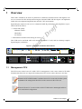
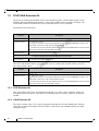
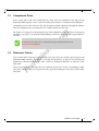


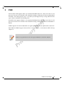
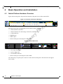
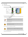

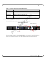
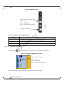
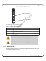

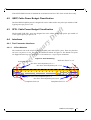

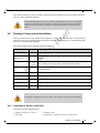
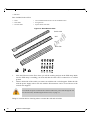
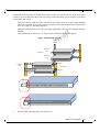

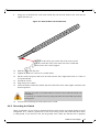
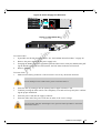

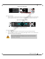
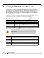
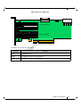
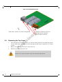


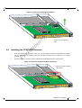


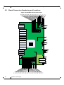

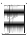
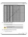
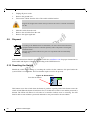

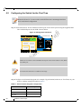


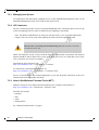

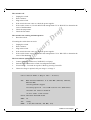

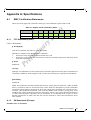


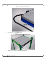


![MC95XX Series Regulatory Guide [English] (P/N 72-118502](http://vs1.manualzilla.com/store/data/005760097_1-2f741b3a88b00c5f81d3f7718b174271-150x150.png)