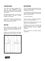
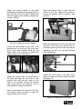
1
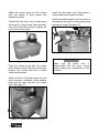
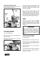
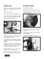
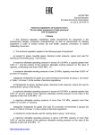
CX110 12” SLOW SPEED COLD SAW User Manual TABLE OF CONTENTS Specific Safety Instructions ------------------------------------------------------------------ 3 Features ------------------------------------------------------------------------------------------ 4 Physical Features ------------------------------------------------------------------------------ 5 Un-packing --------------------------------------------------------------------------------------- 6 Setup ---------------------------------------------------------------------------------------------- 6 Proper Grounding ------------------------------------------------------------------------------ 7 Assembly ----------------------------------------------------------------------------------------- 8 Test Run ------------------------------------------------------------------------------------------ 11 Basic Controls ----------------------------------------------------------------------------------- 11 Cutting Angle------------------------------------------------------------------------------------- 12 Vise------------------------------------------------------------------------------------------------- 12 Work-Stop ---------------------------------------------------------------------------------------- 14 Blade Change------------------------------------------------------------------------------------ 14 Cutting Fluid-------------------------------------------------------------------------------------- 15 Operation ----------------------------------------------------------------------------------------- 15 Maintenance ------------------------------------------------------------------------------------- 16 Cleaning ------------------------------------------------------------------------------------------ 16 Lubrication ---------------------------------------------------------------------------------------- 16 Gearbox Oil--------------------------------------------------------------------------------------- 16 Troubleshooting --------------------------------------------------------------------------------- 17 Wiring Diagram ---------------------------------------------------------------------------------- 20 Recommended Cutting Parameter --------------------------------------------------------- 21 Parts Diagram and Parts List ---------------------------------------------------------------- 22 Warranty ------------------------------------------------------------------------------------------ 26 2 SAFETY INSTRUCTIONS Extreme caution should be used when operating all power tools. Know your power tool, be familiar with its operation, read through the owner’s manual and practice safe usage procedures at all times. Always read and understand the user manual before operating the machine. Connect your machine only to the matched and specific power source. Always wear safety glasses when operating your machine. This machine is designed to cut metal construction materials of different shapes and profiles. The materials may be required for fabrication workshops, machinist shops, and general construction work. To obtain good running-in of the machine it is advisable to start using it at intervals of about half an hour. This operation should be repeated two or three times, after which the machine may be used continuously. Disconnect the power source when changing blade and / or making adjustments. Always check that the work-piece is securely clamped and that long pieces are suitably supported. All operations must be performed with the guards in place to ensure safety. Immediately release the start/run/trigger button if the blade should get stuck in a cut. Switch off the machine before raising the machine head. Then open the vise and remove the work-piece. Lastly, check the blade teeth for any damage. If any of the teeth are broken, replace the saw blade. Always make sure that any tools used for adjustments are removed before operating the machine. Make sure you have read and understood all the safety instructions in the manual and you are familiar with your CX110, before operating it. Failure to do so, could result serious personal injuries and damage to the machine. WARNING! The safety instructions given above can not be complete because the environment in every shop is different. Always consider safety first as it applies to your individual working conditions. 3 CX110 COLD SAW FEATURES MODEL CX110 - 12" SLOW SPEED COLD SAW As part of the growing line of Craftex CX-Series machineries, we are proud to offer the CX110 a 12” Slow Speed Cold Saw. By following the instructions and procedures laid out in this user manual, you will receive years of excellent service and satisfaction. The CX110 is a professional tool and like all power tools, proper care and safety procedures should be adhered to. Motor................................................................2-1/2 HP, 220 V, 16 Amp Coolant Pump ..................................................1/8 HP Coolant Tank Size............................................5 L Spindle Speed..................................................52 RPM Maximum Vise Opening ...................................4-3/4" (120mm) with Quick Release CUTTING CAPACITIES AT 90° Solid .................................................................2-3/8" (60mm) Hollow ..............................................................4" (100mm) Square .............................................................3-1/4" x 3-1/4" (82mm x 82mm) CUTTING CAPACITIES AT 45° Solid .................................................................2" (50mm) Hollow ..............................................................3-1/2" (90mm) Square .............................................................3" x 3" (75mm x 75mm) Approximate Weight.........................................195 Kg Made in ............................................................Taiwan Warranty ..........................................................3 Years 4 CX110 - 12” SLOW SPEED COLD SAW PHYSICAL FEATURES Trigger Switch Control Handle ON/OFF Button Blade Guard Power Indicator Light Vise Coolant Pump Switch Vise Hand Wheel Emergency Stop Button Vise Quick Release Lever 2-1/2 HP Motor Work-Stop Splash Guard Angle Indicator Scale Miter Lock Lever Cabinet Stand Cover Plate Mounting Holes 5 UNPACKING MOUNTING The machine is properly packaged in a crate for safe transportation. When unpacking, carefully inspect the crate and ensure that nothing has been damaged during transit. The CX110 cabinet stand comes with four mounting holes that allow you to mount the machine to the shop floor. While doing the inventory if you can not find any part, check if the part is already installed on the machine. The CX110 is a very heavy machine. Use a forklift truck or other mechanical devices when transporting the machine. Lag shield anchors with lag bolts and studs are two popular methods for anchoring an object to a concrete floor. To mount the machine: Once the stand is completely assembled, position it in the desired location. Mark the floor through the four holes on the stand and move the stand away. SETUP When setting up your machine, you will want to find an ideal spot where your cold saw will most likely be positioned most of the time. Consider your complete work environment before placing your machine in the ideal spot. Figure-1 CX110 dimensions 6 Drill holes on the floor and install the mounting hardware into the floor using the method that best fits your specific application. Place the stand over mounting hardware and secure it. PROPER GROUNDING Grounding provides a path of least resistance for electric current to reduce the risk of electric shock. The machine should be wired by a qualified electrician according to C.E.C (Canadian Electrician Code). WARNING! Improper connection of the equipmentgrounding conductor can result in a risk of electric shock. Check with a qualified electrician if you are in doubt as to whether the outlet is properly grounded. It is strongly recommended not to use extension cords with your CX110. Always try to position your machine close to the power source so that you do not need to use extension cords. If you really find it necessary to use an extension cord, make sure the extension cord does not exceed 50-feet in length and the cord is 14-gauge to prevent motor damage. 7 ASSEMBLY Follow the instructions below, to assemble your CX110: Take the accessories and coolant tank out of the stand and set aside for later use. Place the stand on the floor where you want to place your machine. Use lifting straps and position it around the collar of the moveable jaw and motor as shown in figure-2. Figure-3 Securing the machine onto the stand Attach the coolant tank bracket to the inside of the stand and secure it using screws and washers provided. See figure-4. Figure-2 Lifting straps around the motor and the jaw of the CX110 Once the lifting straps are properly positioned around the machine and the forks of the fork truck, lift the machine. Figure-4 Installing the coolant tank bracket Use a wrench and remove the hex head screw from the oil fill hole shown in figure-5. Align the four setscrews on the base of the machine with the four holes on the stand and lower the machine onto the stand. Direct the setscrews into the holes and position the machine onto the stand. See figure-3. Figure-5 Removing the screw from the oil fill hole 8 Attach the control handle to the head assembly by threading its threaded end into the oil fill hole until it is a tight fit. Make sure that the trigger switch pointing upwards as shown in figure-6. Once the support roller is level with the mouth of the vise, tighten the screws to secure the support roller in position. See figure-8. Figure-8 Support roller Figure-6 Installing the control handle Locate the open socket at the side of the electrical box on the top of the motor and plug in the control handle cable into the open socket. Use a wrench to tighten the cable connector nut. See figure-7. Figure-7 Connecting the cable to the socket Attach the support roller to the left side of the base and align the two holes on the support roller with the two holes on the base of the machine. Secure the support roller using screws and washers, do not fully tighten the screws at this time. Insert the threaded end of the stop bar into the hole on the side of the vise and turn it clockwise until snug. Secure the stop bar by tightening the hex nut counter-clockwise onto the stop bar. Figure-9 Installing the stop bar Attach the cover plate to the side of the stand and secure it using screws provided. See figure-10. Place a level across the mouth of the vise and support roller and raise or lower the support roller until it is level. Figure-10 Installing the cover plate 9 Attach the coolant pump into the coolant tank and secure it using screws and washers provided. Connect the flow tube to the coolant pump and secure it using a hose clamp provided. Use a flat head screw driver to tighten the screw on the hose clamp. Install the rear stand cover and secure it using washers and screws provided. Attach the splash guard to the front side of the machine and secure it using screws and washers provided. See figure-13. Figure-13 Installing the splash guard Figure-11 Coolant pump Place the coolant pump with the coolant tank inside the stand onto the coolant tank bracket. The coolant tank has a divider which holds the tank. Attach one end of the drain hose onto the hose connector, underside of the machine base and the other end into the coolant tank. See figure-12. Figure-12 Coolant tank inside the stand 10 WARNING! Make sure the power cord is disconnected from the power source before making any adjustments to the machine. TEST RUN BASIC CONTROLS Once the machine is completely assembled, test run your machine to make sure it runs properly. The basic controls of the CX110 are described below. Use the following figures and description to get familiar with your saw. To test run the machine: Make sure you have read and understood the instructions given in this user manual and the machine is set up properly. Make sure that there is oil in the machine. See page-16 for details. Make sure all the tools and objects used during assembly are removed from the machine. ON/OFF SWITCH Turns the machine power to the machine ON/OFF. POWER INDICATOR LIGHT Glows green when machine is turned ON. COOLANT PUMP SWITCH Turns the coolant pump ON/OFF. EMERGENCY STOP BUTTON Shuts off the machine incase of emergency. Connect the cord to the power source and turn the machine ON. The machine should run smoothly with little or no vibration. If there is unusual noise or excessive vibration on the machine, shut off the machine immediately. Investigate and correct it before operating the machine. See page-17 for TROUBLESHOOTING. Turn OFF the machine. Figure-14 CX110 Control panel TRIGGER SWITCH Turns the motor ON, spinning the blade and activating the coolant pump. MITER LOCK LEVER Releases or locks the head in position for angled cuts. WORK-STOP Allows to set a particular distance from the blade, producing multiple same length cuts. VISE HAND WHEEL Opens and closes the vise jaw to clamp the work-piece. 11 VISE QUICK RELEASE LEVER Quickly opens and closes the vise jaws for repetitive clamping procedure. Rotate the saw to the desired angle, using the scale as guide shown in figure-16. Lock the head in position by moving the miter lock lever to the right. Now, lower the blade and test the clearance. Make sure the blade is not touching the jaws of the vise when lowered. If the blade touches the jaws of the vise, adjust the vise so that the blade does not come in contact with the jaws of the vise. VISE The vise on CX110 can be adjusted, providing maximum support in different angles. It also features an auxiliary stability bracket for additional support during cutting operation. Figure-15 CX110 saw and vise controls CUTTING ANGLE To se the cutting angle: Make sure the cord is disconnected from the power source. Move the miter lock lever to the left releasing the saw pivot. WARNING! Make sure to check the vise jaws for blade clearance before starting to cut. Failure to do so could cause the blade to come in contact with the jaws during operation and result in damage to the blade. VISE JAW ADJUSTMENT To adjust the vise: Disconnect the cord from the power source. Set the angle of cut by shifting the miter lock lever to the left and rotating the saw to the desired angle. Lower the saw all the way to check for blade clearance. Figure-16 Miter lock lever 12 If the saw blade lowers all the way without hitting the vise jaws or stability bracket, no adjustment is needed. If the saw blade hits the vise jaw or the stability bracket, you will to adjust the vise. VISE QUICK RELEASE LEVER Loosen the screw securing the jaw. See figure-17. The vise on the CX110 is equipped with a quick release lever which allows releasing, repositioning and quickly re-clamping very easy. To use the quick release lever: Disconnect the cord from the power source. Rotate the quick release lever to the upward position. Figure-17 Sliding the jaw Now, slide the jaw so that it is not touching the blade when the blade is lowered. Retighten the screw to secure the jaw in place. Figure-18 Quick release lever STABILITY BRACKET ADJUSTMENT The stability bracket can be placed in two positions and can also be removed depending on the angle of cut. To move the stability bracket: Make sure the cord is disconnected from the power source. Remove the screw securing the stability bracket and reinstall it in the position so that it does not come in contact with the blade when lowered. Open the vise jaw wide enough and place the work-piece between the jaws. Close the jaw within 1/8" of the work-piece. Rotate the quick release lever counterclockwise to secure the work-piece between the jaws. Between cuts, rotate the lever clockwise to release the work-piece, reposition the workpiece and rotate the lever counterclockwise to secure it again. Sometimes you will have to remove the stability bracket depending on the angle of cut. 13 WORK-STOP BLADE CHANGE The CX110 is equipped with a work-stop which allows performing consistent length cuts. To replace the saw blade: To use the work-stop: Remove the cap screw securing the blade guard. See figure-20. Disconnect the cord from the power source. Disconnect the cord from the power source. Loosen the lock knob securing the workstop onto the rod and slide the work-stop to the desired position on the rod. Tighten the lock knob. See figure-19. Figure-20 Removing the blade guard Rotate the blade guard and the linkage out of the way. Figure-19 Adjusting the work-stop Loosen the lock knob on the top of the work-stop and slide the work-stop rod in or out to the desired position. Remove the arbor cap screw and remove the blade flange. Place the blade flange on the new blade. Lower the blade and measure the distance between the end of the work-stop rod and the blade. Adjust the work-stop rod until the distance between the end of the work-stop rod and the blade is equals to the desired length you want to cut on the work-piece. Retighten the lock knob from the top and secure the work-stop rod in position. Before making any cuts, slide the workpiece until it is against the work-stop-rod. 14 Figure-21 Replacing the blade Place the new blade with the flange on the arbor and secure it with by tightening the cap screw. OPERATION Lower the blade guide and reconnect the blade guard, securing it with the cap screw. Once you have read and understood the instructions given in this manual and you are familiar with the basic controls on your CX110, follow the instructions below for safe and efficient cuts. WARNING! Disconnect the cord from the power source. The used cutting fluid presents hazard. Make sure to use personal protection when handling it. Adjust the cutting angle. Adjust the work-stop, if required for the operation being performed. CUTTING FLUID To access and clean/fill the coolant tank: Disconnect the cord from the power source. Remove the rear stand cover to access the coolant tank. Adjust the vise and clamp the work-piece properly. Check to make sure there is cutting fluid in the reservoir and the open the fluid valve behind the blade. Make sure the saw is in the upright position. Wear protective glasses equipments. Connect the cord to the power source. Remove the drain hose from the filter and take the coolant tank out of the cabinet. Push the ON/OFF button to turn the saw ON and turn the coolant pump switch to the right to turn ON the coolant pump. Drain and dispose the cutting fluid following government approved disposal regulations for your area. Use a rag to wipe out residual fluid. Clean the cutting fluid screens in the machine base and the tank. Press the trigger switch to start the blade. Once you see the cutting fluid on the blade, lower the saw to cut the work-piece. Do not force the saw to complete the cut. Lower the saw slowly into the work-piece. Wash out the dirt and debris from the filter. Once the cut is complete, raise the saw, release the trigger. Fill the tank with coolant solution 1:10 ration of coolant to water. Let the blade come to a complete stop before proceeding. Replace the coolant tank in reverse order of removal. 15 MAINTENANCE During the life of your machine, you will need to practice some regular maintenance to keep your lathe in peak performance condition. Check your machine daily for the following before use: * Loose mounting nuts and bolts * Worn or damaged cord * Cutting fluid level * Blade damage * Proper function of the blade guard * Damaged parts * Any other unsafe condition LUBRICATION Disconnect the cord from the power source. Clean the vise lead screw using a rag. Apply multipurpose grease to the vise lead screw and distribute it by opening the closing the vise several times. GEARBOX OIL With regular use, the oil in the gearbox must be drained and replaced every six months. To change the gearbox oil: CLEANING Disconnect the cord from the power source. Treat the machine with care, keep it clean and grease and lubricate it regularly. Only through good care you can be sure that the working quality of the machine will remain constant. Raise the saw all the way up. Oil, grease and cleaning agents are pollutants and must not be disposed off through the drains or in normal garbage. Dispose of those agents in accordance with current local environmental regulations. Cleaning rags impregnated with oil, grease and cleaning wool in a suitable closed vessel and disposed of in an environmentally sound way. Do not put them with normal garbage. Vacuum excess metal chips and wipe off the remaining debris and cutting fluid with a dry cloth. Remove the oil sight glass shown in figure22 and lower the saw forward allowing all the oil to drain out. Figure-22 Oil fill / drain plug location Raise the saw back all the way up. Pour in new oil from the fill plug shown in figure-22. Reinstall the control handle. 16 TROUBLESHOOTING FAULT CAUSE Too fast advance Wrong cutting speed TOOTH BREAKAGE Wrong tooth pitch Low quality disk Ineffective gripping of the part in the vise. Previously broken tooth left in the cut. Cutting resumed on a groove made previously. Insufficient lubricating refrigerant or wrong emulsion. PREMATURE DISK WEAR REMEDY Decrease advance, exerting less cutting pressure. Change disk speed and/or diameter. See chapter “ Material classification and choice of disks” and the Table of cutting speed s according to disk diameter. Choose a suitable disk. See chapter “ Material classification and choice of disks”. Use a better quality disk. Check the gripping of the part. Accurately remove all the parts left in. Make the cut elsewhere, turning the part. Check the level of the liquid in the tank. Increase the flew of lubricating Sticky accumulation of material on the refrigerant, checking that the hole and the liquid outlet pipe are not blocked. disk. Check the blend of lubricating coolant and choose a better quality disk. See chapter “ Material classification Wrong running in of the disk . and choice of disks” in the paragraph on Running in the disk. Change disk speed and / or diameter. Wrong cutting speed. See Chapter “ Material classification and choice of disks” and the Table of cutting speeds according to disk diameter. Unsuitable tooth profile. Choose a suitable disk. See Chapter “ Material classification and choice of disks” in the paragraph on Type of disks. Choose a suitable disk. Wrong tooth pitch. See Chapter “ Material classification and choice of disks”. Use a better quality disk. Low quality disk. Check the level of the liquid in the Insufficient lubricating refrigerant. tank. Increase the flow of lubricating refrigerant, checking that the hole and the liquid outlet pipe are not blocked. 17 FAULT CHIPPED DISK CAUSE Hardness, shape or flaws in the material (oxides, inclusions, lack of homogeneity, etc…) Wrong cutting speed. Wrong tooth pitch. Vibrations Disk incorrectly sharpened. Low quality disk. DISK VIBRATION Incorrect emulsion of the lubricating Refrigerant. Wrong tooth pitch. Unsuitable tooth profile. Ineffective gripping of the part in the vise. Dimensions of the solid section too large with respect to the maximum admissible cutting dimensions. Disk diameter incorrect and/or too large. REMEDY Reduce the cutting pressure and/or the advance. Change disk speed and/or diameter. See Chapter ”Material classification and choice of disks” and the Table of cutting speeds according to disk diameter. Choose a suitable disk. See Chapter “Material classification and choice of disks”. Check gripping of the part. Replace the disk with one that is more suitable and correctly sharpened. Use a better quality disk. Check the percentage of water and oil in the emulsion. Choose a suitable disk. See Chapter “Material classification and choice of disks”. Choose a suitable disk. See Chapter “Material classification and choice of disks” in the paragraph on Type of disks. Check the gripping of the part. Abide by the instructions. Decrease the disk diameter, adapting it to the dimensions of the part to be cut, the cutting part of the disk must not be too large for the shape of the part to be cut. RIDGES ON THE CUTTING SURFACE Disk diameter incorrect and/ or too large. Ineffective gripping of the part in the vise. Too fast advance. Disk teeth are worn. Insufficient lubricating refrigerant. Teeth do not unload shavings well. 18 Decrease the disk diameter, adapting it to the dimensions of the part to be cut, the cutting part of the disk must not be too large for the shape of the part to be cut. Check the gripping of the part. Decrease advance, exerting less cutting pressure. Sharpen the tool. Check the level of the liquid in the tank. Increase the flow of lubricating refrigerant, checking that the hole and the liquid outlet pipe are not blocked. Choose a blade with a larger tooth pitch that allows better unloading of shavings and that holds more lubricating refrigerant. FAULT CUT OFF THE STRAIGHT CAUSE Too fast advance. Ineffective gripping of the part in the vise. Disk head off the straight. Disk sides differently sharpened. Disk thinner than the commercial standard. Dirt on the gripping device. REMEDY Decrease advance, exerting less cutting pressure. Check the gripping of the part which may be moving sideways. Adjust the head. Choose tool quality carefully in every detail as regards type and construction characteristics. Carefully clean the laying and contact surfaces. Decrease advance, exerting less cutting pressure. Increase speed. Choose a suitable disk. See Chapter “Material classification and choice of disks”. Sticky accumulation of material on the Check the blend of lubricating coolant and choose a better quality disk. disk. Check the level of the liquid in the Insufficient lubricating refrigerant. tank. Increase the flow of lubricating refrigerant, checking that the hole and the liquid outlet pipe are not blocked. BLADE STICKS IN THE Too fast advance. CUT Low cutting speed. Wrong tooth pitch. 19 CX110 WIRING DIAGRAM 20 Extra-hare steel R=950-1000 N/mm2 Hear-treated steel R=950-1300 N/mm2 Austentic stainless steel R=500-800 N/mm2 Martensitic stainless Steel R=500-800 N/mm2 Aluminium and alloys R=200-400 N/mm2 Aluminium and alloys R=300-300 N/mm2 Copper R=200-350 N/mm2 Phosphor bronze R=400-600 N/mm2 Hard bronze R=600-900 N/mm2 Brass R=200-400 N/mm2 Alloyed brass R=200-400 N/mm2 Titanium and alloys R=300-800 N/mm2 18° 15° 12° 10° 12° 15° 12° 22° 20° 20° 15° 12° 16° 12° 18° 18° 15° α 8° 8° 8° 6° 6° 8° 6° 8° 10° 8° 10° 8° 8° 16° 16° 8° 8° 8° °T mm 5 4 4 3 2 4 4 4 6 5 6 5 4 5 5 4 3 2 10-20 Vt m/1’ 50 30 20 15 9 20 20 25 1100 200 400 400 120 600 500 50 19 35 Av mm/1’ 160 130 110 60 35 50 50 100 1800 400 600 800 160 1100 700 160 130 130 °T mm 7 6 6 4 3 6 6 8 7 8 7 8 6 7 4 4 3 SECTION TO BE CUT ( IN MM ) 20-40 Vt m/1’ 45 30 20 15 9 19 19 23 1000 180 350 400 110 600 400 45 18 30 Av mm/1’ 150 120 110 60 33 45 45 100 1700 400 600 700 150 1100 600 150 120 110 °T mm 10 9 8 6 4 8 8 8 12 10 11 10 8 10 10 6 5 4 40-60 Vt m/1’ 45 25 18 14 9 18 18 22 900 160 300 350 100 550 350 45 18 30 Av mm/1’ 140 110 100 50 30 45 45 90 1600 350 550 700 140 1000 600 140 110 110 °T mm 12 12 11 9 6 11 11 11 16 12 14 12 10 12 12 10 6 5 60-90 Vt m/1’ 40 25 17 14 8 17 17 20 800 160 250 300 90 550 350 45 17 30 Av mm/1’ 130 110 50 50 28 40 40 80 1400 300 550 600 130 900 500 130 110 110 °T mm 14 14 14 12 8 14 14 14 18 14 17 14 12 16 16 12 6 5 90-110 Vt m/1’ 40 20 15 13 8 15 15 19 700 140 200 250 70 500 300 40 16 28 Av mm/1’ 110 100 80 45 25 40 40 880 1300 300 500 600 110 900 500 110 100 100 °T mm 16 16 16 14 10 16 16 16 20 16 18 16 14 18 18 14 8 6 110-130 Vt m/1’ 35 20 14 13 7 14 14 17 600 130 150 200 60 500 300 35 16 26 Av mm/1’ 100 90 70 45 25 35 35 70 1100 250 500 500 100 800 400 100 90 90 °T mm 18 16 16 14 12 16 16 16 20 16 20 18 16 18 18 16 10 6 130-150 Vt m/1’ 30 15 12 12 7 12 12 16 500 130 120 150 50 450 200 30 15 24 Av mm/1’ 90 80 60 40 22 35 35 60 900 250 400 400 90 800 400 90 80 80 RECOMMENDED LUBRICANTS Emulsion – Cutting oil 6 Dry Kerosene Dry Emulsion Cutting oil Tubes and beams 0.025 D R=300-600 N/mm2 Hard steel R=750-950 N/mm2 20° Tube and beams 0.05 D R=300-600 N/mm2 Semi-hard steel R=500-700 N/mm2 γ CUTTING ANGLES Grey cast iron Mild steel R=350-500 N/mm2 RECOMMENDED CUTTING PARAMETER Emulsion 21 CX110 PARTS DIAGRAM AND LIST 22 23 24 25 WARRANTY CRAFTEX 3 YEARS LIMITED WARRANTY Craftex warrants every product to be free from defects in materials and agrees to correct such defects where applicable. This warranty covers three years for parts and 90 days for labour (unless specified otherwise), to the original purchaser from the date of purchase but does not apply to malfunctions arising directly or indirectly from misuse, abuse, improper installation or assembly, negligence, accidents, repairs or alterations or lack of maintenance. Proof of purchase is necessary. All warranty claims are subject to inspection of such products or part thereof and Craftex reserves the right to inspect any returned item before a refund or replacement may be issued. This warranty shall not apply to consumable products such as blades, bits, belts, cutters, chisels, punches etceteras. Craftex shall in no event be liable for injuries, accidental or otherwise, death to persons or damage to property or for incidental contingent, special or consequential damages arising from the use of our products. RETURNS, REPAIRS AND REPLACEMENTS To return, repair, or replace a Craftex product, you must visit the appropriate Busy Bee Tools showroom or call 1800-461-BUSY. Craftex is a brand of equipment that is exclusive to Busy Bee Tools. For replacement parts directly from Busy Bee Tools, for this machine, please call 1-800-461-BUSY (2879), and have your credit card and part number handy. 26 All returned merchandise will be subject to a minimum charge of 15% for re-stocking and handling with the following qualifications. Returns must be pre-authorized by us in writing. We do not accept collect shipments. Items returned for warranty purposes must be insured and shipped pre-paid to the nearest warehouse Returns must be accompanied with a copy of your original invoice as proof of purchase. Returns must be in an un-used condition and shipped in their original packaging a letter explaining your reason for the return. Incurred shipping and handling charges are not refundable. Busy Bee will repair or replace the item at our discretion and subject to our inspection. Repaired or replaced items will be returned to you pre-paid by our choice of carriers. Busy Bee reserves the right to refuse reimbursement or repairs or replacement if a third party without our prior authorization has carried out repairs to the item. Repairs made by Busy Bee are warranted for 30 days on parts and labour. Any unforeseen repair charges will be reported to you for acceptance prior to making the repairs. The Busy Bee Parts & Service Departments are fully equipped to do repairs on all products purchased from us with the exception of some products that require the return to their authorized repair depots. A Busy Bee representative will provide you with the necessary information to have this done. For faster service it is advisable to contact the nearest Busy Bee location for parts availability prior to bringing your product in for repairs.