1
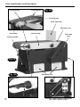
Code: 501258
AWEBDS610 Belt
& Disc Sander
Hole assembly instructions including floor stand
Floor Stand
Code 100234
Axminster Tool Centre,
Unit 10 Weycroft Avenue, Axminster, Devon EX13 5PH
axminster.co.uk
Index of Contents
Page No.
Index of Contents
Declaration of Conformity
Optional Accessories
What’s in the Box
General Instructions for 230V Machines
Assembly
Specification
Parts Identification and Description
Raising the Linisher to Vertical
Changing the Sanding Belt
Tracking the Belt
Changing the Sanding Disc
Maintenance
Optional Floor Stand Assembly
Parts Breakdown/LIst
Notes
02
02
03
03-04
04-05-06
07-08
09
09-10-11-12-13-14
15
16
17
17
17
18-19-20
21-22
23
Declaration of Conformity
Copied from CE Certificate
The undersigned, F. Mocking authorised by
Qingdao Capital Resource Electric Co., Ltd.
155 Zhuzhou Road, Qingdao, Shandong 266101
P.R. China declares that this product:
Model number
(Belt & Disc Sander) BDS610
manufactured by Qingdao Capital Resource Electric
Co.is in compliance with the following standards or
standardisation documents in accordance with Council
Directives
2006/42/EC
2004/108/EC
2006/95/EC
2002/96/EC
EN 61029-1:2009
symbols below advise that you follow the correct
Warning The
safety procedures when using this machine.
Fully read manual
and safety instructions
before use
02
Ear protection
should be worn
Eye protection
should be worn
Dust mask
should be worn
Two Man
Assembly
HAZARD
Motor gets hot
What’s in the Box
Quantity
Item
Model Number:
1 No.
1 No.
1 No.
1 No.
1 No.
1 No.
4 No.
4 No.
2 No.
1 No,
2 No.
2 No.
1 No.
1 No.
1 No.
1 No.
2 No.
1 No.
1 No.
Belt & Disc Sander (Sanding Belt Fitted)
Sanding Disc Table with Bracing Struts attached
Righthand Side Disc Table Trunnion
Lefthand Side Disc Table Trunnion
Righthand Side Disc Table Support Bracket
Lefthand Side Disc Table Support Bracket
M6 Pan Head Machine Screws
M6 Hex Head Bolts
M6 Star Handled Bolts and Washers
Work Stop Plate for the linisher.
M6 Countersunk Bolts
M6 Knurled Knobs and Washers
6mm Allen Key
4mm Allen Key
Mitre fence Fixture and 'T' bar.
Mitre Fence Plate
Star Handled Nuts
254mm Diameter Self Adhesive Sanding Disc.
Instruction Manual
Model Number
BDS610
(Product Code: 501257)
Optional Accessories
1 No.
4 No.
2 No.
2 No.
2 No.
2 No.
Belt & Disc Sander Floor Stand
Legs
Short Rails
Long Rails
Short Stretchers
Long Stretchers
(Product Code: 100234)
1 No. Packet Containing:
24 No. M6 Coach Bolts
24 No. Large 6mm Washers
32 No. M6 Nuts
8 No. Small 6mm Washers
4 No. M6x90 Hex Head Bolts
03
What’s in the Box
Having opened the box, remove all the components stowed in the packaging. Place these
carefully to one side. Remove the top packaging and lift the machine out of the box; using the lift
up handle at the motor end and the moulded hand grip in the other, and place upon a clear flat
surface, taking care not to trap or pinch the power cable under the chassis.
Remove any other items from the box. Having unpacked your sander and its various
components; if you do not wish to retain the packaging please dispose of it responsibly,
especially any polystyrene, most of the rest of the packaging is biodegradable.
Please read though the Section entitled Identification and Description of parts of the
Sander, as this will ensure that you better understand the terminology we will use
during the assembly and setting up phases.
General Instructions for 230V Machines
Good Working Practices/Safety
The following suggestions will enable you to observe good working practices, keep yourself and
fellow workers safe and maintain your tools and equipment in good working order.
!
WARNING!!
KEEP TOOLS AND EQUIPMENT OUT
OF THE REACH OF YOUNG CHILDREN
Mains Powered Tools (General) Disc & Belt Sander
Primary Precautions
These machines are supplied with a moulded 13 Amp. Plug and 3 core power cable. Before
using the tool inspect the cable and the plug to make sure that neither are damaged. If any
damage is visible have the tool inspected/repaired by a suitably qualified person. If it is
necessary to replace the plug, it is preferable to use an 'unbreakable' type that will resist
damage on site. Only use a 13 Amp plug, make sure the cable clamp is tightened securely. Fuse
at 13 Amp It is also good practice to use switch outlets. If extension leads are to be used, carry
out the same safety checks on them, and ensure that they are correctly rated to safely supply the
current that is required for your machine. This machine is intended primarily for inside/workshop
usage.
Work Place/Environment.
Always mount the machine on a flat, level stable surface. There are several methods of
achieving this, bolting the machine directly to a 'good solid workbench', bolting the machine to a
sturdy base board that can be clamped to the 'good solid workbench'; create an independent
entity by bolting the machine to its own stand. However you mount your machine, make sure it is
fastened down and stable before use.
Paper belts and discs do not respond well to wet or damp conditions. In the worst case the
adhesives holding the belt and the abrasives fail completely, the belts fall apart and the abrasive
becomes a soggy mess against the edge of your work piece. Try to keep the machine in a
reasonably dry, warm environment. If this is not possible, if the machine is to remain unused for
some time, at least remove the belt, put in a 'plastic' bag and store in a warm dry place.
04
General Instructions for 230V Machines
I'm afraid I can offer no suggestions for the disc, unless you have upgraded to some form of
'velco'.fastening method, in which case, do the same as with the belt. (P.S. don't forget… don't
leave the spare belts/discs in the damp either).
Keep the work area as uncluttered as is practical, this includes personnel as well as material.
Under no circumstances should CHILDREN be allowed in work areas.
Specific to Sanding machines
!
Warning The sanding disc can not be declutched from the belt and vice versa, both
functions are active when the machine is running. Remember this, and do not leave loose
objects of any description, on the machine if it is going to be used.
Once the sander is mounted, carry out any setting operations, (mitre, tilt..?), and remove all tools
used in the setting operations (if any) and place safely out of the way. If you are working long
lengths of material arrange for extra support beyond the boundary of the machine and check you
have sufficient room to manoeuvrer the material through all the operations you will wish to carry
out.
It is good practice to leave the machine unplugged until work is about to commence, also make
sure to unplug the machine when it is not in use. Always disconnect by pulling on the plug body
and not the cable.
After fitting a new sanding disc, it is good practice to lightly sand across the left side of the disc
with a reasonable sized (20mm x 50mm) piece of timber to make sure the sanding disc is
correctly 'seated' on the disc. The sanding action will press the sanding disc firmly back against
the disc itself.
It is not good practice to wear gloves whilst sanding as one tends to lose the 'feel' of the
workpiece/sander contact, but obviously this removes the safety barrier between your fingers
and the sanding surface. Remain focused and exercise caution whilst sanding.
DO NOT sand very small pieces of work with bare hands, try to construct some form of holder.
Make sure you are comfortable before you start work, balanced, not reaching etc., If the work
you are carrying out is liable to generate excessive grit or dust or chips, wear the appropriate
safety clothing, goggles, masks etc., If the work operation appears to be excessively noisy, wear
ear-defenders. If you wear your hair in a long style, wearing a cap, safety helmet, hairnet, even a
sweatband, will minimise the possibility of your hair being caught up in the rotating parts of the
tool, likewise, consideration should be given to the removal of rings and wristwatches, if these
are liable to be a 'snag' hazard.
Do not work with cutting/abrasive tools of any description if you are tired, your attention is
wandering or you are being subjected to distraction. A deep graze, a lost fingertip or worse; is
not worth it!
Do not use the machine within the designated safety areas of flammable liquid stores or in areas
where there may be volatile gases. There are very expensive, very specialised machines for
working in these areas, THIS IS NOT ONE OF THEM.
05
General Instructions for 230V Machines
Check that sanding surfaces are still sufficiently abrasive to carry out the work you intend.
Sanding belt cleaning sticks are an efficient method of prolonging the life of the belts and discs,
and will also maintain their operating performance.
Check that the belts or discs are undamaged, edges pick up on the workpiece and will cause the
medium to tear, often very rapidly with accompanying sharp flapping edges.
Always offer the workpiece to the belt/disc so that the motion carries the work against the
restraining surface, (i.e. the work stop or the table, (use the left hand side of the disc).
Do not press too heavily against the sanding surface, all this will do is slow the sander down.
Remember sanders work by removing small particles of material quickly and heavy pressure
works adversely to the cutting process, further it will accelerate the rate of 'clogging' of the
abrasive surfaces, rendering the machine less efficient.
If you are attempting to sand inside curves (over the 'tracking drum') do not press at all, other
than to keep the workpiece in contact with the surface, any pressure could upset the tracking
geometry. As there is no cushioning effect to the belt passing around the drum, expect an added
vibration and compensate for it.
Sanding of certain types of timber may make the fitting of dust extraction mandatory; in order to
comply with the directives of the HSE. However, even if it is not mandatory, it is strongly
recommended that you consider fitting dust extraction. It will certainly reduce the level of dust
and grit, and as it helps to remove the waste more quickly, will certainly prolong the longevity of
the abrasives.
Above all, OBSERVE…. make sure you know what is happening around you, and USE YOUR
COMMON SENSE.
06
Assembly
In order to reduce the footprint of the machine for packaging, several items are dismounted
from the machine and need to be re-affixed. Please locate the disc table trunnions and identify
them as left and right handed, do likewise with the disc table support brackets. Identify them
as left and right hand. Locate the 4 off M6 Pan Head Machine screws. Loosely screw the table
trunnions to the chassis as shown in ( fig 1).
Offer up the left hand table support bracket (fig. 2) and introduce, from the outside, one of the
star handled bolts with a washer, through the
graduated bracing strut, screw the bolt into the
Fig 1
threaded boss at the foot of the trunnion, (this is to
effectively act as a third hand whilst you are
fastening the table to the table brackets) introduce
the spigot of the table bracket into the trunnion,
and set the support barrack approximately level
(fig. 3). Repeat for the other side. Locate the M6
Hex head bolts, set the table on the support
brackets and Manoeuvre the table and the
brackets until you can fit the bolts through the
brackets into the table, screw in loosely (fig.
4).When all screws and bolts are fitted, proceed to
tighten up all screws and bolts, commencing with
the Pan head screws, then the hex head bolts.
Tighten gradually, and swing the table whilst you
Loosely screw the table
are tightening (remember the table has to tilt up
trunnions to the chassis
and down after all the tightening is complete. Do
not over tighten the bolts, remember the table is a casting.
Fig 2
Disc table
bracing strut
Fig 3
Star handled bolt
Fig 4
M6 hex bolt
Fig 5
Tighten up all screws and bolts
07
Assembly
Set the table to 90° according to the graduated scales on the bracing struts and the index
marker. Use a known 90° reference (square?) and check that the table is set correctly to the disc
(fig.6) If it is not, reset the table until it is correct and then reset the index marker to the scale on
the bracing strut. (fig. 6a)
Index marker
90˚ Square
Fig 6a
Fig 6
Star handled bolt
Scale
Fig 7
Fit the mitre fence to the slot in the table, set square and
check that the face of the mitre fence is perpendicular to the
disc (fig 7). If it is not, loosen the table fixing bolts and slew
the table until it is correct. (Take care to leave sufficient gap
between the table edge and the disc to fit the abrasive disc).
Re-tighten the bolts.
Clean the surface of the disc with a degreasing cleaner,
(methylated spirit, acetone (nail polish remover borrowed
from the female side of the family), if you don't have a
proprietary cleaner).
Allow to dry off and wipe over with a clean dry cloth. Locate
Table slot
the sanding disc, peel the cover from the adhesive surface
Mitre fence
and apply CAREFULLY to the disc, use a piece of cloth in
Square
your hand or wear a glove, to firmly press the abrasive to the
disc. (You don't have to go mad pressing the sanding disc down now, the application can be
reinforced by a gentle sanding action across the face when you first use the new sanding disc.
Locate the work stop plate for the linisher, and fit to the anchor strut using the M6 countersunk
bolts, washers and knurled knobs provided, as shown in fig 8. Clear away any odds and sods,
bits and pieces etc. Make sure you have read and understood the rest of the manual
Work stop
plate
08
Fig 8
Specification
Model
Product Code
Rating
AWEBDS610
501258
Hobby
Power
Belt Speed
Belt Size
Diameter of Disc
Table Size Disc
Dust Extraction Outlet
Overall L x W x H
Weight
800W
517m/min
150 x 1,220mm
254mm
365 x 200mm
62mm
620 x 560 x 480mm
47kg
Parts Identification and Description
Chassis
(See fig 9)
This is the main body of the machine, all the other components are
mounted onto the chassis.
Linisher body
(See fig 10)
This is the long flat box that carries the linishing belt, it is mounted on the
chassis via a swivel joint about the drive axle. It mounts the tensioning/
tracking drum, and the various mechanisms for applying tension to and
tracking of the belt. It also mounts the platen which is the support and
planar reference for belt.
Linisher platen
(See fig 10a)
This is the flat surface of the machine that supports the belt and maintains
it in plane during sanding operations. The platen itself is impregnated with
a medium to reduce friction (therefore heat) and scuffing abrasion of the
belts. This aids the smooth passage of the belt and increases its longevity.
Motor
(Unseen)
Unseen. The motor is housed in the chassis body. A pulley and drive belt
connect the motor shaft output to the pulley on the drive drum.
NVR start/stop
buttons
(See fig 9d)
The NVR Start/Stop buttons, beneath the “quick” action stop shroud.
Standard marking with ‘I’ indicating Start and ‘O’ indicating Stop.
Ventilation
grills
(See fig 10)
Preformed ventilation grills fitted to the chassis body to allow air to be
ducted to the motor for cooling. Ensure that the grills are not covered
during operation or that they do not become clogged.
Drive belt cover
(See fig 10)
A moulded plastic cover that guards the drive belt. It must be removed to
effect the changing of the drive belt.
Drive drum
This is the drum that provides the belt movement. It is fixed to the chassis
and is referenced to the platen and is the reference against which the
'tracking drum' works in order to maintain the tension and the linear motion
of the belt. The drive drum axle fits through a mandrel, around which the
swivel joint of the linisher can be rotated. (See fig 10a)
09
Parts Identification and Description
Fig 9b
Fig 9a
Fig 9c
Swivel mandrel
Belt tension lever
Knurled knob
Star handle bolt
Dust deflector
Fig 9
Dust
extraction
port
Aluminium
fence plate
Carrying
handle
Chassis
Disc table trunnion
Disc table
Disc
table
support
brackets
Emergency
stop
Off
Disc table
bracing strut
10
Disc
On
Fig 9d
NVR On/Off switch
Parts Identification and Description
Tracking drum
(See fig 10a)
This is the 'idler drum' mounted on the linisher body that supports the other
end of the belt, and provides the tension to the belt that enables the drive
drum to drive it. The tension is provided by an expansion spring within the
linisher body. The spring can be compressed by a lever arrangement to
enable the belts to be changed. The axis of the drum can be altered to allow
the belt to be 'tracked' along the platen.
Tracking
adjustor
The axis of the tracking drum is established by the 'dead end' of its axle
resting in the bottom of a slotted bracket, and the live end being driven up
or down an anchored thread which acts as the Tracking Adjustor. The
anchored thread is turned by a star knob handle, which will tilt the axis
positive or negative, causing the belt to move to the left or right until it
achieves its linear 'track'. (See fig 10b)
Tensioning lever This is the lever that controls the tensioning spring which acts on the
(See fig 9c)
tracking drum. Pushing the lever towards the drive drum end will slacken
the tension, push the lever the other way to re-apply the tension.
Work stop plate
and mounting
strut
(See fig 10)
This is a flat metal plate fastened to its mounting strut as shown in the fig 10.
The mounting strut looks a complicated arrangement, but is in fact a simple
solution to provide a robust structure utilising light weight construction. The
mounting strut must be removed in order to replace the belt. The mounting
strut also provides an anchor for the dust deflector.
Linishing belt
(See fig 10a)
This is the flat belt that is driven along the linishing platen to provide the
long, wide flat abrasive surface upon which the majority of sanding is
carried out . Belts of different abrasive types and loadings are available.
Swivel mandrel
(See fig 9a)
This is the mounting for the clench joint of the linisher, the joint can be
slackened off to allow the linisher to be tilted up to and including the
vertical.
Dust extraction
port
(See fig 9)
The dust extraction port is moulded in to the chassis cover, directly below
the dust deflector over the drive drum. The lower section of the chassis is
accessed by the extraction port, so the resulting draught will remove the
dust from the disc sander, and also encourage airflow past the motor.
Disc
(See fig 9)
A 10 inch alloy disc, mounted on the end of the drive drum axle. It
can mount a wide range of abrasive types and grits.
Disc table
(See fig 9)
A good sized table pivoted in trunnions. The table has a 'T' slot
machined into it, parallel to the front edge to allow the mounting of the
mitre fence attachment. The underside of the front edge of the table is
bevelled so that the table can be tilted down without fouling the sanding
disc.
Disc table
trunnions
(See fig 9)
These are the handed castings bolted through to the chassis that mount
the table.
11
Parts Identification and Description
Linisher platen
Tracking drum
Fig 10a
Linishing belt
Work stop plate
Mounting strut
Drive drum
Linisher body
Drive belt
cover
Carrying handle
Fig 10
Fig 10b
12
Tracking adjuster
Ventilation grills
Drive belt cover removed showing the
drive belt & pulley system
Parts Identification and Description
Disc table
support
brackets
(See fig 9)
These are the handed castings bolted to the table, they have the
pivoting spigots that engage in the trunnions to allow the table to tilt.
Disc table
bracing struts
(See fig 9)
Two open quadrant struts, each pre mounted to the table through a
swivel joint. The quadrants have a graduated scale stamped into them
which allows for the table to be set to a known angle. There is an index
pointer on the left trunnion that reads against the scale. The bracing
struts are clamped at their lower ends by star handled bolts and washers
through to a threaded boss in the foot of the trunnion casting.
Mitre fence
(See fig 12)
The mitre fence assembly is mounted on a 'T' bar which engages in the
slot machined in the table. It is capable of being turned through ± 60°.
There is a large aluminium facing plate that can be fixed to the mitre
fence to provide a greater bearing surface.
Carrying handle
& moulding
handle grip
(See fig 9 & 10)
There is a hinged carrying handle on one side of the sander. The other
side is a handle grip moulded into the chassis of the sander.
!
Please read the Instruction Manual prior to using your new
machine; as well as the operating procedures for your new
machine, there are numerous hints and tips to help you to use the
machine safely and to maintain its efficiency and prolong its life.
Keep this Instruction Manual readily accessible for any others who
may also be required to use the machine.
13
Parts Identification and Description
Fig 11
Aluminium
fence plate
‘T’ bar
Slot
Mitre fence
Fence plate
clamping knobs
Fig 12
Mitre fence
clamp
Scale
Fig 13
14
Raising the Linisher to Vertical
If you require to raise the linishing table to the vertical using the 6mm Allen Key provided
loosen the swivel mandrel locking bolt ( See fig 16 ).
It is suggested that you also remove the dust deflector by removing the two screws & washers
(See figs 14 & 15 ) so that the dust will be driven down straight down to the rear of the dust
extraction port. Put the screws, washers & cover safely aside.
Raise the linisher table either to its vertical stops or to the position required (See fig 17) and
re-tighten the swivel mandrel bolt. After use remember to refit the dust deflector (or the dust will
shoot out straight off the end of the m/c).
Fig 14
Fig 15
To remove the dust deflector unscrew
the two screws & washers
Dust defector removed
Fig 17
Fig 16
Using a 6mm allen key loosen
the swivel mandrel locking bolt
Raise the linisher to the required angle
& re-tighten the swivel mandrel
locking bolt
15
Changing the Sanding Belt
!
Disconnect the machine from the mains supply.
Remove the workstop plate and strut, by unscrewing the knurled knob on the end of the pivot
bar, and the two star handled bolts (See fig 18), lift the strut, plate and dust deflector clear, (See
fig 19) place all components aside carefully. Unlock the swivel mandrel locking bolt & raise the
Linisher slightly so it is clear of the horizontal stops then clamp down the bolt. Release the belt
tension by pressing the lever toward the tracking drum end.(See fig 20). Slide the belt off the
machine.(See fig 21) Inspect the new belt, ensure that there are no tears or rips (especially along
the edges), check the direction arrows on the inner surface of the belt and fit accordingly. The
direction of the arrows on the belt surface against the linisher platen should point to the drive
drum.
Note. If you are using an old belt , and the arrow marking has worn off, check the direction of
travel as in fig 22. Set the belt about the centre of the linishing table and reset the tension by
pressing the lever toward the tracking drum end of the machine. See page 18 for instructions on
how to track the belt.
Fig 18
Fig 19
Unscrew the knurled knob & star
handled bolts to remove the work
stop plate & strut
Lift the strut, plate and dust
deflector clear
Fig 20
Fig 21
Linishing belt
Release the belt tension by pulling
the lever toward the tracking drum
Fig 22
Direction of travel
Belt Underlay
Belt Overlay
16
Slide the belt off the machine
Glue Joint
Tracking the Belt
!
Disconnect the machine from the mains supply.
NOTE1 All directions are given from the view point of the operator standing behind the drive
drum end looking down the length of the machine.
The tracking control works as follows:- turning the tracking adjustor clockwise will track the belt
to the left, anti-clockwise will track the belt to the right. DO NOT make large adjustments, and
remember the belt may take some time to react to your alteration. Little by little is a good maxim
to observe when carrying out tracking operations.
NOTE2 NOW here you can wear a glove.
Using your hand roll the belt towards the drive drum end, check that the belt stays in the middle
of the table, if not, adjust the track control slightly and move the belt again, continue until the belt
runs down the centre of the linishing table. When you are comfortable that the belt is tracking in
one line, reconnect the mains supply, and switch the machine ON. Be prepared to carry out a
small adjustment to the original setting as the belt being driven can generate slightly different
dynamics to the belt being 'hand turned'.
Changing the Sanding Disc
Lift the edge of the disc and, gripping firmly, peel the disc away from the plate; turning the plate
as required to free all the disc. Remove and throw away. If you have been extremely fortunate all
the adhesive will have been removed with the disc. As this is rarely the case, be prepared to rub,
scrape, pick etc., to remove all the odd patches of adhesive and render the plate CLEAN. Fit the
new sanding disc as detailed in the instruction “Assembly”.
Maintenance
!
Disconnect the machine from the mains supply.
There is very little mechanical maintenance that can be carried out on the machine. Most
prudent maintenance is preventative and concerned with keeping the machine clean.
Remove the belt and check there is no dust or resin build up on the drums or at the edges of the
platen. At reasonable intervals, remove the ventilation grills, inspect the interior of the chassis,
remove all dust/resin build ups, and blow the motor clean.
Remove the lower sanding disc guard, the dust deflector and the extraction port moulding,
remove any build ups and clean them thoroughly to allow the dust to travel over their
surfaces smoothly. Remove the drive belt cover and check that the belt is not frayed, worn or
loose. Replace all guards and covers, etc., Reconnect to the supply and start up the machine,
check that nothing has disturbed the tracking.
17
Optional Floor Stand Assembly
Overview
The stand is rectangular in shape. The Belt
Disc Sander sits on the stand with the front of
the machine above the narrower side of the
rectangle.
tightening can prevent misalignment). Upright
the frame. (See fig 3) Bolt the machine to the
stand using the M6x90mm hex head bolts, by
pushing the washered bolt through the
chassis, through the stand and securing with a
washer and M6 nut use another M6 nut to lock
the first in place.(See page 6)
Assembling the stand
Fig 1
Locate and identify the 4 legs, the rails (A) and
the stretchers for the stand, (B) and the packet
containing the coach bolts, washers and nuts.
B
The rails are almost symmetrical angle strips,
the rails have 2 holes punched in one face
(2 at each end) and are slightly shorter than
the corresponding stretchers. The rails also
have 2 holes (one at each end) in the adjacent
face to accept the bolts for mounting the
machine. The stretchers are almost asymmetric
angle strips, both the long and the short
stretchers have 2 holes punched in one face
(one each end).
Identify the two shortest rails and the two
shortest stretchers.
Assemble the two 'short' end frames for the
stand. Bolt the components together by putting
the coach bolt through the leg, through the rail
or stretcher, secure with washer and nut.
Tighten the nut only 'finger tight' at this time.
(See fig 1)
A
Fig 2
C
When the two end frames have been
assembled, select one, turn it upside down on
a flat surface and loosely bolt the 'long side'
rails and stretchers (C) in place attach the
other side frame, (keep the interleaving of the
top surfaces of the rails the same, (See fig 2)
i.e. if the top face of the narrow end of the
stand rail is above the top face of the long
side, keep it the same on both sides and both
ends).
When all the components are assembled,
using the flat surface as a reference, tighten up
all the nuts. Check that the mounting holes for
the machine are lined up (introducing one of
the bolts or a screwdriver shaft during
18
C
Optional Floor Stand Assembly
Fig 3
19
Optional Floor Stand Assembly
501258 Belt
Disc Sander
M6x90mm hex
head bolt
Two Man
Assembly
Small 6mm
washer
M6 Nuts
100234 Stand
!
WARNING. The Belt Disc Sander is a heavy piece of equipment.
You are advised to seek help or the use of some form of lifting device, (hoist,
engine crane etc.,) before you attempt to lift or move this machine.
20
Parts Breakdown/LIst
21
Parts Breakdown/List
22
Notes
23
Please dispose of packaging for the product in a responsible manner. It is suitable for recycling.
Help to protect the environment, take the packaging to the local recycling centre and place into the
appropriate recycling bin.
Only for EU countries
Do not dispose of electric tools together with household waste material. In observance of
European Directive 2002/96/EC on waste electrical and electronic equipment and its
implementation in accordance with national law, electric tools that have reached the end of
their life must be collected separately and returned to an environmentally compatible recycling
facility.