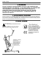
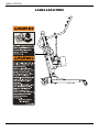
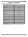
1
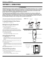
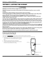
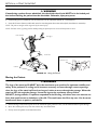
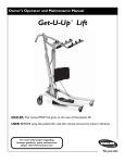
User Manual Stand Up Patient Lift RPS350-1 DEALER: This manual MUST be given to the user of the product. USER: BEFORE using this product, read this manual and save for future reference. For more information regarding Invacare products, parts, and services, please visit www.invacare.com SYMBOL LEGEND WARNING DO NOT OPERATE THIS EQUIPMENT WITHOUT FIRST READING AND UNDERSTANDING THIS MANUAL. IF YOU ARE UNABLE TO UNDERSTAND THE WARNINGS, CAUTIONS AND INSTRUCTIONS CONTACT A QUALIFIED DEALER OR INVACARE TECHNICAL SUPPORT BEFORE ATTEMPTING TO USE THIS EQUIPMENT - OTHERWISE INJURY OR DAMAGE MAY RESULT. ACCESSORIES WARNING Invacare products are specifically designed and manufactured for use in conjunction with Invacare accessories. Accessories designed by other manufacturers have not been tested by Invacare and are not recommended for use with Invacare products. SYMBOL LEGEND "ATTENTION, see instructions for use". "Date of Manufacture" Device contains Lead Acid batteries. DO NOT dispose of batteries in normal household waste. They MUST be taken to a proper disposal site. Contact your local waste management company for information. WARNING - ALWAYS be aware of the Lift Arm. Injury to the patient and/or assistant may occur. WARNING - ALWAYS be aware of the Footrest, especially the patient’s position on the footrest. Injury to the patient and/or assistant may occur. Stand Up Patient Lift 2 Part No. 1078984 TABLE OF CONTENTS TABLE OF CONTENTS SYMBOL LEGEND .............................................................................................. 2 SPECIAL NOTES ................................................................................................ 5 LABEL LOCATION ............................................................................................. 6 PRODUCT PARAMETERS .................................................................................. 7 RPS350-1 Stand Up Patient Lift...........................................................................................................................................7 SECTION 1—GENERAL GUIDELINES ................................................................... 8 Weight Limitation ..................................................................................................................................................................8 Assembling the Lift.................................................................................................................................................................8 Using the Sling.........................................................................................................................................................................8 Operating the Lift...................................................................................................................................................................9 Lifting the Patient ...................................................................................................................................................................9 Transferring the Patient........................................................................................................................................................9 Performing Maintenance.......................................................................................................................................................9 SECTION 2—ASSEMBLY ................................................................................... 10 Unpacking the Patient Lift ................................................................................................................................................. 10 Assembling the Patient Lift................................................................................................................................................ 10 Assembling the Mast Assembly to the Base ............................................................................................................. 10 Prepare Lift for Use ............................................................................................................................................................ 10 Install the Shifter Handle ................................................................................................................................................... 10 Attaching the Battery Charger Mounting Bracket to the Wall ................................................................................ 11 SECTION 3— OPERATION ............................................................................... 12 Locking/Unlocking the Rear Casters .............................................................................................................................. 12 Raising/Lowering the Patient Lift ..................................................................................................................................... 12 Closing/Opening the Legs.................................................................................................................................................. 12 Using the Emergency Stop ................................................................................................................................................ 12 Activating a Mechanical Emergency Release ................................................................................................................. 13 Charging the Battery .......................................................................................................................................................... 13 SECTION 4—LIFTING THE PATIENT ................................................................. 14 Positioning the Stand Up Lift ............................................................................................................................................ 14 Lifting the Patient ................................................................................................................................................................ 15 Moving the Patient .............................................................................................................................................................. 16 SECTION 5—TRANSFERRING THE PATIENT ..................................................... 17 Transferring to a Commode Chair ................................................................................................................................. 18 Transferring to a Wheelchair........................................................................................................................................... 19 Transferring to a Bed ......................................................................................................................................................... 19 SECTION 6—TROUBLESHOOTING .................................................................... 20 Part No. 1078984 3 Stand Up Patient Lift TABLE OF CONTENTS TABLE OF CONTENTS SECTION 7—MAINTENANCE ........................................................................... 21 Maintenance Safety Inspection Checklist....................................................................................................................... 21 Cleaning the Sling and the Lift.......................................................................................................................................... 21 Detecting Wear and Damage........................................................................................................................................... 21 Lubricating the Lift .............................................................................................................................................................. 22 Adjusting the Base............................................................................................................................................................... 22 Adjusting the Knee Pad Height ........................................................................................................................................ 22 Replacing the Electric Actuator ....................................................................................................................................... 23 LIMITED WARRANTY ..................................................................................... 24 Stand Up Patient Lift 4 Part No. 1078984 SPECIAL NOTES SPECIAL NOTES Signal words are used in this manual and apply to hazards or unsafe practices which could result in personal injury or property damage. Refer to the table below for definitions of the signal words. SIGNAL WORD MEANING DANGER Danger indicates an imminently hazardous situation which, if not avoided, will result in death or serious injury. WARNING Warning indicates a potentially hazardous situation which, if not avoided, could result in death or serious injury. CAUTION Caution indicates a potentially hazardous situation which, if not avoided, may result in property damage or minor injury or both. NOTICE THE INFORMATION CONTAINED IN THIS DOCUMENT IS SUBJECT TO CHANGE WITHOUT NOTICE. RADIO FREQUENCY INTERFERENCE Most electronic equipment is influenced by Radio Frequency Interference (RFI). CAUTION should be exercised with regard to the use of portable communication equipment in the area around such equipment. If RFI causes erratic behavior, PUSH the RED Emergency Stop Button IMMEDIATELY. DO NOT turn the Red Emergency Stop Button OFF while transmission is in progress. MAINTENANCE Maintenance MUST be performed ONLY by qualified personnel. Part No. 1078984 5 Stand Up Patient Lift LABEL LOCATION LABEL LOCATION Stand Up Patient Lift 6 Part No. 1078984 PRODUCT PARAMETERS PRODUCT PARAMETERS RPS350-1 Stand Up Patient Lift Height at Sling Hook-up - MAX.: 66 inches Height at Sling Hook-up - MIN.: 40 inches Base Width OPEN: 37 inches Base Width CLOSED: 26 inches Base Height (Clearance): 4.5 inches Base Length: 35.5 inches Overall Height: 49 inches Overall Length: 39 inches Overall Width: 25.8 inches Caster Size (FRONT) Caster Size (REAR) 3.0 inches 5.0 inches Sling Options: Standing or Transfer Sling Material: Polyester Weight Capacity: 350 lbs Weight Out of Carton: 108 lbs Battery: 24V DC (RCHBL) Charger Input: 100-240V AC Charger Output/Charging Time: 29.5V DC Max 6 hours Audio/Visual Low Battery Alarm: Yes Motor Safety Devices: Anti-Entrapment *Approx. Lifts per Charge: *100-200 Cycles per charge Limited Warranty Lift/Electronics: 3 Years/1 Year Emergency Stop Button: Yes *NOTE: Varies depending upon load and stroke. Part No. 1078984 7 Stand Up Patient Lift SECTION 1—GENERAL GUIDELINES SECTION 1—GENERAL GUIDELINES WARNING SECTION 1 - GENERAL GUIDELINES contains important information for the safe operation and use of this product. Check all parts for shipping damage before using. In case of damage, DO NOT use the equipment. Contact the Dealer for further instructions. The Invacare patient lift is NOT a transport device. It is intended to transfer an individual from one seated surface to another (such as a bed to a wheelchair). DO NOT attempt any transfer without approval of the patient’s physician, nurse or medical assistant. Thoroughly read the instructions in this Owner’s Manual, observe a trained team of experts perform the lifting procedures and then perform the entire lift procedure several times with proper supervision and a capable individual acting as a patient. Invacare Stand Assist and Transfer slings are specifically designed to be used in conjunction with Invacare patient lifts. Slings and accessories designed by other manufacturers are not to be utilized as a component of Invacare’s patient lift system. Use the sling that is recommended by the individual’s doctor, nurse or medical assistant for the comfort and safety of the individual that is being lifted. If the patient lift is used in the area of a shower or bath, ensure that the patient lift is wiped clean of any moisture after use. DO NOT store the lift in a damp area or in a damp condition. Periodically inspect all components of the patient lift for signs of corrosion. Replace all parts that are corroded or damaged. The stand up lift may be operated by one healthcare professional for all lifting preparation, transferring from and transferring to procedures with a cooperative, partial weight-bearing patient. However, since medical conditions vary, Invacare recommends that the healthcare professional evaluate the need for assistance and determine whether more than one assistant is appropriate in each case to safely perform the transfer. The use of the patient lift by one assistant should be based on the evaluation of the healthcare professional for each individual case. Weight Limitation DO NOT exceed maximum weight limitation of the patient lift. The weight limitation for the patient lift is 350 lbs. Assembling the Lift DO NOT overtighten mounting hardware. This will damage mounting brackets. Using the Sling Stand Assist Slings: DO NOT use the stand assist sling in combination with the patient lift as a transport device. It is intended to transfer an individual from one resting surface to another (such as a bed to a wheelchair). Stand Assist Slings: Before lifting the patient, make sure the bottom edge of the stand assist sling is positioned on the lower back of the patient and the patient’s arms are outside the stand assist sling. Stand Assist Slings: The belt MUST be snug, but comfortable on the patient, otherwise the patient can slide out of the sling during transfer, possibly causing injury. Transfer Slings: Before lifting the patient, make sure the bottom edge of the transfer sling is at the base of the spine and the patient’s arms are outside the transfer sling. Transfer Slings: DO NOT raise the patient to a full standing position while using the transfer sling, otherwise injury may occur. After each laundering (in accordance with instructions on the sling), inspect sling(s) for wear, tears, and loose stitching. Bleached, torn, cut, frayed, or broken slings are unsafe and could result in injury. Discard immediately. DO NOT alter slings. Be sure to check the sling attachments each time the sling is removed and replaced, to ensure that it is properly attached before the patient is removed from a stationary object (bed, chair or commode). If the patient is in a wheelchair, secure the wheel locks in place to prevent the chair from moving forwards or backwards. Stand Up Patient Lift 8 Part No. 1078984 SECTION 1—GENERAL GUIDELINES Operating the Lift Make sure there is an audible click when mounting battery on the battery charger to confirm proper mounting. Otherwise, injury or damage may occur. Use the handles to push or pull the patient lift. Lifting the Patient Before positioning the legs of the stand up lift around the patient, make sure that the patient’s feet are out of the way of the foot plate, otherwise injury may occur. Adjustments for safety and comfort should be made before moving the patient. Patient's arms should be outside of the sling straps. Before lifting a patient from a stationary object (wheelchair, commode or bed), slightly raise the patient off the stationary object and check that all sling attachments are secure. If any attachment is not correct, lower the patient and correct the problem, then raise the patient and check again. During transfer, with the patient suspended in a sling attached to the lift, DO NOT roll caster base over uneven surfaces that would create an imbalance of the patient lift and could cause the patient lift to tip over. Use steering handle on the mast at ALL times to push or pull the patient lift. Invacare recommends locking the rear swivel casters ONLY when positioning or removing the sling (stand assist or transfer) from around the patient. Invacare does NOT recommend locking of the rear casters of the patient lift when lifting an individual. Doing so could cause the lift to tip and endanger the patient and assistants. Invacare DOES recommend that the rear casters be left unlocked during lifting procedures to allow the patient lift to stabilize itself when the patient is initially lifted from a chair, bed or any stationary object. Transferring the Patient Before transferring, check that the product’s weight capacity can withstand the patient's weight. Wheelchair wheel locks MUST be in a locked position before lowering the patient into the wheelchair for transport. Performing Maintenance Regular maintenance of patient lifts and accessories is necessary to assure proper operation. After the first 12 months of operation, inspect all pivot points and fasteners for wear. If the metal is worn, the parts MUST be replaced. Perform this inspection every six months thereafter. DO NOT overtighten mounting hardware. This will damage mounting brackets. Casters and axle bolts require inspections every six months to check for tightness and wear. Part No. 1078984 9 Stand Up Patient Lift SECTION 2—ASSEMBLY SECTION 2—ASSEMBLY Unpacking the Patient Lift Unpack the components from the shipping carton. Assembling the Patient Lift DETAIL “A” Step Here to Lock Step Here to Unlock WARNING Use only Invacare parts in the assembly of this patient lift. The base legs, the mast, boom, pump assembly and swivel bar are manufactured to specifications that assure correct alignment of all parts for safe functional operation. Locking Lever UNLOCKED Assembling the Mast Assembly to the Base LOCKED NOTE: The mast assembly may be removed from the base for storage or transporting. The mast assembly MUST be properly secured to the base assembly before use. NOTE: For this procedure, refer to FIGURE 2.1. 1. Put the base on the floor. Hex Bolt NOTE: Make sure all four casters make contact with the floor. 2. Lock both rear casters. Refer to Detail “A”. 3. Remove the hex bolt, washers and nut that are located in the U-shape cut-out of the base. 4. Lift the mast to an upright position. 5. Lower the mast onto the mounting bracket. 6. Attach the mast to the base with the hex bolt, washers and nut. Tighten securely. Washer Nut Prepare Lift for Use Washer Mounting Bracket FIGURE 2.1 Assembling the Mast Assembly to the Base Check and tighten all hardware BEFORE use. Install the Shifter Handle NOTE: For this procedure, refer to FIGURE 2.2. 1. Remove the shifter handle from the packaging carton. 2. Thread the shifter handle onto the male adapter on the base. Shifter Handle Male Adapter in Base FIGURE 2.2 Install the Shifter Handle Stand Up Patient Lift 10 Part No. 1078984 SECTION 2—ASSEMBLY Attaching the Battery Charger Mounting Bracket to the Wall NOTE: For this procedure, refer to FIGURE 2.3. 1. Place the battery charger mounting bracket on the wall at the desired position. 2. With a pencil, mark the middle hole position. 3. Measure down 6½ inches from the pencil mark and drill one mounting hole. 4. Install the bottom mounting screw until there is an approximate 1/8-inch gap between the screw head and the wall. 5. Put the battery charger mounting bracket onto the bottom mounting screw. 6. Drill the other two mounting holes. 7. Screw the mounting screws through the battery charger mounting bracket and into the wall. Tighten securely. Mounting Bracket Mounting Screws BOTTOM Mounting Screw CAUTION Make sure there is an audible click when mounting battery on the battery charger to confirm proper mounting. Otherwise, injury or damage may occur. 8. Put the battery charger in place on the mounting bracket. 9. Plug the battery charger into an electrical outlet. FIGURE 2.3 Attaching the Battery Charger Mounting Bracket to the Wall NOTE: An LED will illuminate when power is applied to battery charger. Part No. 1078984 11 Stand Up Patient Lift SECTION 3—OPERATION SECTION 3— OPERATION WARNING DO NOT attempt to transfer a patient without approval of the patient’s physician, nurse, or medical assistant. Thoroughly read the instructions in this owner’s manual, observe a trained team of experts performing the lifting procedures and then perform the entire lift procedure several times with proper supervision and a capable individual acting as a patient. The legs of the stand up lift MUST be in the maximum open position for optimum stability and safety. If the patient is in a sling and it becomes necessary to move through a narrow passage, close the legs of the stand up lift only as long as it takes to move through the passage. When the stand up lift is through the passage, return the legs to the maximum open position. NOTE: The use of the patient lift by one assistant should be based on the evaluation of the health care professional for each individual case. DETAIL “A” Step Here to Lock Step Here to Unlock Locking/Unlocking the Rear Casters • Refer to Detail “A” of Figure 3.1. Raising/Lowering the Patient Lift Locking Lever NOTE: For this procedure, refer to Detail “B”. • To Raise the Patient Lift: Press the up () button on the hand control. NOTE: If the patient lift is raised to the highest level, it may be necessary to pull down gently on the lift arms before the mast will begin to lower. Pull down gently on both arms at the same time to avoid making the lift unstable. • To Lower the Patient Lift: Press the down button () on the hand control. UNLOCKED LOCKED DETAIL “B” - HAND CONTROL DETAILS Up Button Down Button Closing/Opening the Legs • To Close the Legs: Pull the shifter handle OUT and away from the stand-up lift and then to your LEFT until it LOCKS in the notch of the bracket. NOTE: Left is determined by standing behind the stand-up lift facing towards the front casters. Hand Control • To Open the Legs: Pull the shifter handle OUT and away from the stand-up lift and then to your RIGHT until it LOCKS in the notch of the bracket. NOTE: Right is determined by standing behind the stand-up lift facing towards the front casters. DETAIL “C” - EMERGENCY STOP Emergency Button Push in to stop, turn clockwise to reset. Using the Emergency Stop NOTE: For this procedure, refer to Detail “C”. • Push the RED emergency button in to stop the lift arms from raising or lowering. • To reset, rotate the emergency button clockwise. Stand Up Patient Lift FIGURE 3.1 Operating the Patient Lift 12 Part No. 1078984 SECTION 3—OPERATION Activating a Mechanical Emergency Release 6. Primary Emergency Release Place the battery on the control box. Push the top of the battery against the mounting bracket until there is an audible click. NOTE: For this procedure, refer to FIGURE 3.2. NOTE: This procedure will bring the boom down if the hand control is not functioning properly. To activate the primary emergency release, insert the tip of a pen into the Emergency Down hole () in the control box. Control Box Emergency Down Hole Secondary Emergency Release NOTE: For this procedure, refer to FIGURE 3.3. NOTE: All patient lift actuators are equipped with a mechanical emergency release. The mechanical release will enable the actuator to retract without power. NOTE: Use the primary emergency release first before using the secondary emergency release procedure. This procedure should only be used if the primary emergency release procedure is not functioning or is unreachable. NOTE: The lift MUST be under a load for the mechanical release to function. FIGURE 3.2 Primary Emergency Release To activate the secondary emergency release, pull up on the RED emergency grip and pull down on the boom at the same time. Charging the Battery RED Emergency Grip NOTE: For this procedure, refer to FIGURE 3.4. NOTE: Invacare recommends the battery be recharged daily to prolong battery life. NOTE: An audible alarm will sound when battery is low. 1. Lift UP on the handle on the back of the battery. 2. Lift the battery up and away from the control box. CAUTION Make sure there is an audible click when mounting battery on the battery charger. Otherwise, injury or damage may occur. 3. FIGURE 3.3 Primary Emergency Release Battery Handle STEPS 1, 2, 4 and 5) Place the battery on the battery charger. Push the top of the battery against the mounting bracket until there is an audible click. Battery Charger (STEP 3) NOTE: The charge LED will illuminate. When charged, the LED will stop illuminating. Control Box (STEP 6) NOTE: It will take approximately four hours to charge a battery that requires a full charge. 4. Lift UP on the handle on the back of the battery. 5. Lift the battery up and away from the battery charger. CAUTION Make sure there is an audible click when mounting battery on the battery charger. Otherwise, injury or damage may occur. An audible “click” will be heard when properly installed (STEPS 3 and 6) FIGURE 3.4 Primary Emergency Release Part No. 1078984 13 Stand Up Patient Lift SECTION 4—LIFTING THE PATIENT SECTION 4—LIFTING THE PATIENT WARNING DO NOT exceed the maximum weight limitation of 350 lbs. DO NOT attempt to any transfer without approval of the patient’s physician, nurse or medical assistant. ALWAYS keep hands and fingers clear of moving parts to avoid injury. Invacare patient slings are made specifically for use with Invacare patient lifts. For the safety of the patient, DO NOT intermix patient slings and patient lifts of different manufacturers. Individuals that use the standing patient sling MUST be able to support the majority of their own weight, otherwise injury may occur. The legs of the stand-up lift MUST be in the maximum open position and the shifter handle locked in place for optimum stability and safety. If the patient is in a sling and it becomes necessary to move through a narrow passage, close the legs of the stand-up lift only as long as it takes to move through the passage. Once the stand-up lift is through the passage, return the legs of the stand-up lift to the maximum open position and lock the shifter handle IMMEDIATELY. DO NOT move the patient if the patient sling is not properly connected to the attachment points on the patient lift. Check that the patient sling is properly connected to the attachment points BEFORE lifting the patient. During transfer, with the patient suspended in the patient sling, DO NOT roll the base of the patient lift over any uneven surfaces that would cause the patient lift to become unstable. Use the steering handle on the mast assembly at all times to push or pull the stand up lift. Positioning the Stand Up Lift NOTE: For this procedure, refer to FIGURE 4.1. NOTE: Refer to General Guidelines on page 8 before proceeding and observe all warnings indicated. NOTE: Before positioning the legs of the patient lift under a bed, make sure that the area is clear of any obstructions. 1. Ensure the legs of the stand up lift are in the maximum open position. If not, use the shifter handle to open the legs. 2. Position the stand up lift using the mast handle. 3. Press the DOWN button on the hand control to lower the lift arms for easy attachment to the sling. UP Button DOWN Button Hand Control FIGURE 4.1 Hand Control Buttons Stand Up Patient Lift 14 Part No. 1078984 SECTION 4—LIFTING THE PATIENT Lifting the Patient WARNING DO NOT exceed the maximum weight limitation of 350 lbs. Individuals that use the standing patient sling MUST be able to support the majority of their own weight, otherwise injury may occur. DO NOT move the patient if the sling is not properly attached to the attachment points on the stand up lift. Make sure that the sling is properly attached BEFORE lifting the patient. If any attachments are not properly in place, correct the problem. When the sling is elevated a few inches off the stationary surface and before moving the patient, check again to make sure the sling and all attachments are securely in place. If any problem is found, lower the patient back onto the stationary surface and correct the problem - otherwise, injury or damage may occur. Adjustments for safety and comfort should be made before moving the patient. Invacare patient slings are made specifically for use with Invacare patient lifts. For the safety of the patient, DO NOT intermix patient slings and patient lifts of different manufacturers. NOTE: For this procedure, refer to FIGURE 4.2 on page 16. NOTE: Refer to the patient sling Owner’s Manual, P/N 1023891, for more information. NOTE: The patient MUST be in a seated position first. Use the head section of the bed to get the patient upright then move legs over the side of the bed. 1. Instruct the patient to hold onto the hand grips on both sides of the stand up lift (Detail “A” of FIGURE 4.2). 2. Instruct the patient to lean back into the standing or transfer sling. WARNING Standing Slings - Before lifting the patient, make sure the bottom edge of the standing sling is positioned on the lower back of the patient and the patient’s arms are outside the sling. Transfer Slings - Before lifting the patient, make sure the bottom edge of the transfer sling is at the base of the spine and the patient’s arms are outside the sling. Invacare does not recommend locking the rear casters of the stand up lift when lifting and transferring an individual. Doing so could cause the lift to tip and endanger the patient and assistants. Invacare recommends that the rear casters be left unlocked during lifting and transferring procedures to allow the stand up lift to stabilize itself when the patient is initially lifted from and transferred to a chair, bed or any stationary object. 3. Ensure the following: A. The patient’s knees are secure against the knee pad. B. The patient’s feet are properly positioned on the foot plate. C. Slings: • Standing Sling - the bottom edge of the standing sling is positioned on the patient’s lower back. • Transfer Sling - the bottom edge of the transfer sling is at the base of the patient’s spine. • Either Sling Style - the patient’s arms are outside the sling. D. The rear casters are unlocked. E. The legs are in the maximum open position. Part No. 1078984 15 Stand Up Patient Lift SECTION 4—LIFTING THE PATIENT WARNING If transferring a patient from a wheelchair, the wheelchair wheel locks MUST be in the locked position before lowering the patient into the wheelchair. Otherwise, injury may occur. 4. If transferring from a wheelchair, lock the wheel locks on the wheelchair (Detail “B” of FIGURE 4.2). 5. Press the UP arrow button on the hand control to raise the patient above the surface (bed, wheelchair or commode). NOTE: The patient’s weight will be supported by the stand up lift. NOTE: The lower center of gravity provides stability making the patient feel more secure and the lift easier to move. Mast Handle Handgrip Knee Pad DETAIL “A” - WHEEL LOCK Wheel Lock Casters Foot Plate FIGURE 4.2 Lifting the Patient Moving the Patient WARNING The legs of the stand up lift MUST be in the maximum open position for optimum stability and safety. If the patient is in a sling and it becomes necessary to move through a narrow passage, close the legs of the stand up lift only as long as it takes to move through the passage. When the stand up lift is through the passage, return the legs to the maximum open position. DO NOT, during transfer of a patient suspended in the lift sling, roll caster base over uneven surfaces that would create an imbalance of the lift. This could cause the lift to tip over. Use the mast handle at all times to push or pull the lift. 1. Ensure the legs of the stand up lift are in the maximum open position. If not, use the shifter handle to open the legs. 2. Move the stand up lift away from the surface they were lifted from. 3. Slowly move the patient to the desired surface. Stand Up Patient Lift 16 Part No. 1078984 SECTION 5—TRANSFERRING THE PATIENT SECTION 5—TRANSFERRING THE PATIENT WARNING DO NOT attempt any transfer of a patient without the approval of the patient’s physician, nurse or medical assistant. DO NOT move the patient if the sling is not properly connected to the attachment points of the stand up lift. Check that the sling is properly connected to the attachment points prior to lifting a patient. If any attachments are not properly in place, correct the problem. When the sling is elevated a few inches off the stationary surface and before moving the patient, check again to make sure that all sling attachments are secure. If any attachments are not properly in place, lower the patient back onto the stationary surface and correct this problem - otherwise, injury or damage may occur. Adjustments for safety and comfort should be made before moving the patient. DO NOT use slings and stand up lifts of different manufacturers. Invacare slings are made specifically for use with Invacare stand up lifts. Otherwise, injury or damage may occur. Invacare does not recommend locking the rear casters of the stand up lift when lifting and transferring an individual. Doing so could cause the lift to tip and endanger the patient and assistants. Invacare recommends that the rear casters be left unlocked during lifting and transferring procedures to allow the stand up lift to stabilize itself when the patient is initially lifted from and transferred to a chair, bed or any stationary object. The legs of the stand up lift MUST be in the maximum open position for optimum stability and safety. If the patient is in a sling and it becomes necessary to move through a narrow passage, close the legs of the stand up lift only as long as it takes to move through the passage. When the stand up lift is through the passage, return the legs to the maximum open position. If it is necessary to close the legs to maneuver the stand up lift under a bed, close the legs only as long as it takes to position the stand up lift over the patient and lift the patient off the surface of the bed. When the legs of the stand up lift are no longer under the bed, return the legs to the maximum open position. Be sure to check the sling attachments each time the sling is removed and replaced to ensure that it is properly attached before the patient is removed from a surface. The use of one assistant is based on the evaluation of the health care professional for each individual case. Part No. 1078984 17 Stand Up Patient Lift SECTION 5—TRANSFERRING THE PATIENT Transferring to a Commode Chair DETAIL “A” WARNING Invacare recommends locking the rear swivel casters only when positioning or removing the sling from around the patient. NOTE: For this procedure, refer to FIGURE 5.1. 1. Lift the patient from the side of the bed. 2. Press the UP button on the hand control to elevate the patient high enough to clear the arms of the commode chair. Their weight will be supported by the stand up lift. 3. Guide the patient onto the commode chair. This may require two assistants. 4. Press the down arrow button to lower the patient onto the commode chair. 5. Lock the rear swivel casters on the stand up lift. 6. Perform one of the following: • Standing Sling - unhook the standing sling from the attachment points on the lift. • Transport Sling i. DETAIL “B” Unhook the transport sling from the bottom attachment points on the lift. ii. Lift up on the patient’s legs and remove the thigh supports from underneath the patient. iii. If desired, unhook the transport sling from the top attachment points on the lift. NOTE: The patient can remain in the upper portion of the transfer sling while using the commode. 7. Instruct or assist the patient in lifting their feet off the footplate. 8. Remove the sling from around the patient. 9. Unlock the casters and pull the lift away from the commode. DETAIL “C” FIGURE 5.1 Transferring to a Commode Chair Stand Up Patient Lift 18 Part No. 1078984 SECTION 5—TRANSFERRING THE PATIENT Transferring to a Wheelchair DETAIL “A” NOTE: For this procedure, refer to FIGURE 5.2. 1. Ensure the legs of the lift with the patient in the sling are in the open position. 2. Move the wheelchair into position. Refer to Detail “A”. 3. Engage the rear wheel locks of the wheelchair to prevent movement of the wheelchair. Refer to Detail “B”. WARNING DO NOT place the patient in the wheelchair if the locks are not engaged. The wheelchair wheel locks MUST be in a locked position before lowering the patient into the wheelchair for transport. Otherwise, injury may result. 4. Position the patient over the wheelchair. 5. Lower the patient into the wheelchair. 6. Unhook the sling from all attachment points on the lift. Refer to Detail “C”. 7. Instruct patient to lift their feet off the footplate. Assist the patient if necessary. 8. Remove the sling from around the patient. 9. Pull the lift away from the wheelchair. DETAIL “B” DETAIL “C” Transferring to a Bed NOTE: For this procedure, refer to FIGURE 5.3. NOTE: The lower center of gravity provides stability making the patient feel more secure and the lift easier to move. NOTE: The lift arms will stay in position until the DOWN button on the hand control is pressed. 1. FIGURE 5.2 Transferring to a Wheelchair Position the patient as far over the bed as possible. NOTE: If patient is being transferred from a surface that is lower than the bed, raise the patient above the surface of the bed. The patient should be elevated just high enough to clear the bed with their weight fully supported by the lift. 2. Press the DOWN button and lower the patient onto the bed. WARNING Invacare recommends locking the rear swivel casters ONLY when positioning or removing the sling from around the patient. 3. 4. Lock the rear swivel casters on the stand up lift. Unhook the sling from all attachment points on the lift. 5. Instruct the patient to lift their feet off of the footplate. Assist the patient if necessary. 6. Remove the standing or transport sling from around the patient. 7. Unlock the rear swivel casters and pull the lift away from the bed. Part No. 1078984 FIGURE 5.3 Transferring to a Bed 19 Stand Up Patient Lift SECTION 6—TROUBLESHOOTING SECTION 6—TROUBLESHOOTING SYMPTOMS FAULTS SOLUTION Noisy or dry sound from pivots. Needs lubrication. Refer to Lubricating the Lift on page 22. Electric actuator fails to lift when button is pressed. Hand-control or actuator connector loose. Check the hand control and actuator connections. Re-connect as necessary. Battery low. Charge batteries. Refer to Charging the Battery on page 13. RED emergency stop button pressed IN. Rotate RED emergency stop button CLOCKWISE until it pops out. Battery not connected properly to control box. Reconnect the battery to the control box. Refer to Charging the Battery on page 13. The connecting terminals are damaged. Replace the battery pack. Refer to Charging the Battery on page 13. Electric actuator in need of service or load is too high. Refer to Adjusting the Base on page 22. Contact Dealer if service is required. Unusual noise from actuator. Actuator is worn or damaged or spindle is bent. Replace the actuator or contact Dealer. Refer to Replacing the Electric Actuator on page 23. Lift arms will not lower from the uppermost position. Lift arms require a minimum weight load to lower from the uppermost position. Pull down slightly on the lift arms. NOTE: If problems are not remedied by the suggested means, please contact your dealer or Invacare. Stand Up Patient Lift 20 Part No. 1078984 SECTION 7—MAINTENANCE SECTION 7—MAINTENANCE Maintenance Safety Inspection Checklist ITEM INITIALLY INSTITUTIONAL INSPECT/ADJUST MONTHLY THE BASE Inspect for missing hardware. Legs open/close with ease. Inspect casters and axle bolts for tightness and wear. Inspect casters for smooth swivel and roll. Inspect wheels are clear of debris. X X X X X X X X X X X X X X X THE MAST Mast MUST be securely assembled to lift arms. Inspect for bends or deflections. X X X X X X X X X X X X X X X X X X ELECTRIC ACTUATOR Check for wear or deterioration. (IF DAMAGED, CONTACT DEALER) Cycle to ensure smooth quiet operation. X X X X X X CLEANING Whenever necessary. X X X SLINGS CHECK ALL SLING ATTACHMENTS each time it is used to ensure proper connection and patient safety. Inspect sling material for wear. Inspect straps for wear. X X X X X X X X X THE LIFT ARMS AND LINKAGE Check all hardware and attachment points. Inspect for bends or deflections. Inspect bolted joints of lift arms for wear. Inspect to ensure that the lift arms are centered between the base legs. IN-HOME INSPECT EVERY SIX (6) MONTHS NOTE: Follow the maintenance procedures described in this manual to keep your patient lift in continuous service. The Invacare Patient Lift is designed to provide a maximum of safe, efficient and satisfactory service with minimum care and maintenance. All parts of the Invacare Lift are made of the best grades of steel, but metal to metal contact will wear after considerable use. There is no adjustment or maintenance of the casters, other than cleaning, lubrication and checking axle and swivel bolts for tightness. Remove all debris, etc. from the wheel and swivel bearings. If any parts are worn, replace these parts IMMEDIATELY. If you question the safety of any part of the lift, contact your Dealer IMMEDIATELY. Cleaning the Sling and the Lift The sling should be washed regularly in water temperature not exceeding 180°F (82°C) and a biological solution. A soft cloth, dampened with water and a small amount of mild detergent, is all that is needed to clean the patient lift. The lift can be cleaned with non-abrasive cleaners. Detecting Wear and Damage It is important to inspect all stressed parts, such as slings, lifting arm and any pivot for slings for signs of cracking, fraying, deformation or deterioration. Replace any defective parts IMMEDIATELY and ensure that the lift is not used until repairs are made. Part No. 1078984 21 Stand Up Patient Lift SECTION 7—MAINTENANCE Lubricating the Lift Square Linkage Rods The Invacare lift is designed for minimum maintenance. However, a six month check and lubrication should ensure continued safety and reliability. Keep lift and slings clean and in good working order. Any defect should be noted and reported to your dealer as soon as possible. The casters MUST swivel and roll smoothly. A light grease (waterproof auto lubricant) may be applied to the ball bearing swivel of the casters once a year. Apply more frequently if the casters are exposed to extreme moist conditions. Linkage Rod Adjusting the Base NOTE: For this procedure, refer to FIGURE 7.1 on page 22. 1. Check the squareness of the legs when in the CLOSED position. 2. Place a square on the inside of the legs and base to determine the 90° alignment. 3. Adjust the linkage rods until 90° alignment is achieved. FIGURE 7.1 Adjusting the Base Adjusting the Knee Pad Height NOTE: For this procedure, refer to FIGURE 7.2. Knee Pad WARNING Adjustment Pin NEVER adjust the knee pad while patient is in the standing position. NEVER try to adjust the knee pad while the lift is moving. ALWAYS make sure that the adjustment pins are engaged in corresponding height adjustment holes before use. 1. Adjustment Pin Pick a height setting that will be comfortable to the patient and provide the necessary support. FIGURE 7.2 Adjusting the Knee Pad Height NOTE: The knee pad should be positioned so that the knee portion of the leg is in contact with the pad. 2. Using both hands, pull both adjustment pins outward at the same time. 3. Position the knee pad to the desired height and release adjustment pins into the corresponding alignment holes. 4. Check to make sure that both pins are engaged. Stand Up Patient Lift 22 Part No. 1078984 SECTION 7—MAINTENANCE Replacing the Electric Actuator 1. Remove the bottom nut, washer and shoulder bolt that secure the electric actuator to the mast mounting bracket. 2. Rest the lift arm on your shoulder and remove the top nut, bolt, bracket and bushing from the lift arm mounting bracket. 3. Remove the electric actuator. 4. Reverse STEPS 1-3 to install the new electric actuator. WARNING DO NOT overtighten mounting hardware. This will damage mounting brackets. Bracket Bolt Washer Bolt Washer Bushing Bolt Bolt Washer Washer Bushing FIGURE 7.3 Replacing the Electric Actuator Part No. 1078984 23 Stand Up Patient Lift LIMITED WARRANTY PLEASE NOTE: THE WARRANTY BELOW HAS BEEN DRAFTED TO COMPLY WITH FEDERAL LAW APPLICABLE TO PRODUCTS MANUFACTURED AFTER JULY 4, 1975. This warranty is extended only to the original purchaser/user of our products. This warranty gives you specific legal rights and you may also have other legal rights which vary from state to state. Invacare warrants the products manufactured to be free from defects in materials and workmanship for a period of three years on the lift and one year on the electric components from the date of purchase. If within such warranty period any such product shall be proven to be defective, such product shall be repaired or replaced, at Invacare’s option, with refurbished or new parts. This warranty does not include any labor or shipping charges incurred in replacement part installation or repair of any such product. Product repairs shall not extend this warranty - coverage for repaired product shall end when this limited warranty terminates. Invacare’s sole obligation and your exclusive remedy under this warranty shall be limited to such repair and/or replacement. For warranty service, please contact the dealer from whom you purchased your Invacare product. In the event you do not receive satisfactory warranty service, please write directly to Invacare at the address on the back cover, provide dealer’s name, address, date of purchase, indicate nature of the defect. Invacare Corporation will issue a serialized return authorization. The defective unit or parts MUST be returned for warranty inspection using the serial number, when applicable as identification within 30 days of return authorization date. DO NOT return products to our factory without our prior consent. C.O.D. shipments will be refused; please prepay shipping charges. LIMITATIONS AND EXCLUSIONS: THE FOREGOING WARRANTY SHALL NOT APPLY TO SERIAL NUMBERED PRODUCTS IF THE SERIAL NUMBER HAS BEEN REMOVED OR DEFACED, PRODUCTS SUBJECTED TO NEGLIGENCE, ACCIDENT, IMPROPER OPERATION, MAINTENANCE OR STORAGE, PRODUCTS MODIFIED WITHOUT INVACARE’S EXPRESS WRITTEN CONSENT (INCLUDING, BUT NOT LIMITED TO, MODIFICATION THROUGH THE USE OF UNAUTHORIZED PARTS OR ATTACHMENTS; PRODUCTS DAMAGED BY REASON OF REPAIRS MADE TO ANY COMPONENT WITHOUT THE SPECIFIC CONSENT OF INVACARE, OR TO A PRODUCT DAMAGED BY CIRCUMSTANCES BEYOND INVACARE’S CONTROL, AND SUCH EVALUATION WILL BE SOLELY DETERMINED BY INVACARE. THE WARRANTY SHALL NOT APPLY TO PROBLEMS ARISING FROM NORMAL WEAR OR FAILURE TO ADHERE TO THE INSTRUCTIONS IN THIS MANUAL. THE FOREGOING WARRANTY IS EXCLUSIVE AND IN LIEU OF ALL OTHER EXPRESS WARRANTIES. IMPLIED WARRANTIES, IF ANY, INCLUDING THE IMPLIED WARRANTIES OF MERCHANTABILITY AND FITNESS FOR A PARTICULAR PURPOSE, SHALL NOT EXTEND BEYOND THE DURATION OF THE EXPRESSED WARRANTY PROVIDED HEREIN AND THE REMEDY FOR VIOLATIONS OF ANY IMPLIED WARRANTY SHALL BE LIMITED TO REPAIR OR REPLACEMENT OF THE DEFECTIVE PRODUCT PURSUANT TO THE TERMS CONTAINED HEREIN. INVACARE SHALL NOT BE LIABLE FOR ANY CONSEQUENTIAL OR INCIDENTAL DAMAGES WHATSOEVER. SOME STATES DO NOT ALLOW EXCLUSION OR LIMITATION OF INCIDENTAL OR CONSEQUENTIAL DAMAGE, OR LIMITATION ON HOW LONG AN IMPLIED WARRANTY LASTS, SO THE ABOVE EXCLUSIONS AND LIMITATIONS MAY NOT APPLY TO YOU. THIS WARRANTY SHALL BE EXTENDED TO COMPLY WITH STATE OR PROVINCIAL LAWS AND REQUIREMENTS. Invacare Corporation www.invacare.com USA One Invacare Way Elyria, Ohio USA 44036-2125 800-333-6900 Canada 570 Matheson Blvd E Unit 8 Mississauga Ontario L4Z 4G4 Canada 800-668-5324 © 2013 Invacare Corporation. All rights reserved. Republication, duplication or modification in whole or in part is prohibited without prior written permission from Invacare. Trademarks are identified by ™ and ®. All trademarks are owned by or licensed to Invacare Corporation or its subsidiaries unless otherwise noted. Part No. 1078984 Rev I - 11/13