1
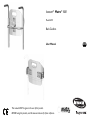
Invacare® Matrx® MX1 Model IMX1 Back Cushion User Manual This manual MUST be given to the user of the product. BEFORE using this product, read this manual and save for future reference. EN This product complies with Directive 93/42/EEC concerning medical devices. © 2011 Motion Concepts. All rights reserved. Republication, duplication or modification in whole or in part is prohibited without prior written permission from Motion Concepts. Trademarks are identified by ™ and ®. All trademarks are owned by or licensed to Motion Concepts or its subsidiaries unless otherwise noted. Invacare® Matrx® MX1 2 Part No. 1171914 CONTENTS 1 GENERAL 4 Symbols ........................................................................................................4 Overview .....................................................................................................4 Important Information ........................................................................4 Invacare Matrx MX1 ...........................................................................4 Outer Cover.........................................................................................5 Limited Warranty - North America ......................................................5 2 SAFETY 4 6 General Guidelines ....................................................................................6 Intended Use...............................................................................................6 Installation Information.............................................................................6 Operating Information..............................................................................7 Weight Limitation and Model Numbers...............................................7 3 MONO MOUNT 5 8 5 Installation Overview ................................................................................8 Included Items.......................................................................................8 Tools Required...........................................................................................8 Before Installation ......................................................................................8 Installing the Mounting Hardware..........................................................9 Installing the Tracking Plate on the Back Shell................................. 11 Part No. 1171914 3 Installing the Back Shell onto the Mounting Hardware .................. 11 Adjusting the Back Height ..................................................................... 12 Adjusting the Back Angle....................................................................... 12 Removing the Mono Mount Hardware.............................................. 13 DUAL MOUNT 14 Installation Overview.............................................................................. 14 Included Items.................................................................................... 14 Tools Required ........................................................................................ 14 Before Installation ................................................................................... 14 Installing the Angle Adjustable Brackets onto the Back Shell ....... 15 Clamp Body Adjustment........................................................................ 15 Installing the Band Clamps .................................................................... 16 Installing the Back.................................................................................... 16 Adjusting the Back Height ..................................................................... 17 Adjusting the Back Angle and Back Depth ........................................ 18 After Installation ...................................................................................... 18 LUMBAR SUPPORT 19 Installing/Adjusting the Lumbar Support............................................ 19 MAINTENANCE 19 Cleaning ..................................................................................................... 19 General Cleaning............................................................................... 19 Laundering........................................................................................... 19 Inspection .................................................................................................. 19 Reuse.......................................................................................................... 19 Invacare® Matrx® MX1 1 GENERAL 1 General 1.1 Symbols Signal words are used in this manual and apply to hazards or unsafe practices which could result in personal injury or property damage. See the information below for definitions of the signal words. 1.2 WARNING Warning indicates a potentially hazardous situation which, if not avoided, could result in death or serious injury. CAUTION Caution indicates a potentially hazardous situation which, if not avoided, may result in property damage or minor injury or both. Gives useful tips, recommendations and information for efficient, trouble-free use. Overview Important Information The best way to avoid problems related to pressure sores is to understand their causes and your role in a skin management program. Your therapist and physician should be consulted if you have questions regarding individual limitations and needs. All cushions should be selected carefully. Working with your therapist and physician is the best way to assure that a cushion choice matches your individual needs. As the needs of the individual become more complex, cushion evaluation becomes more important. Invacare Matrx MX1 The Invacare Matrx MX1 back is contoured to provide precise orientation within the wheelchair for optimal postural support. The foam is oversized to provide extra comfort and protection. The Invacare Matrx MX1 back includes a movable foam lumbar pad that can be installed/inserted behind the existing foam cushion to provide additional positioning capability. Refer to Lumbar Support on page 19 for instructions on how to insert and adjust your lumbar support. Invacare® Matrx® MX1 4 Part No. 1171914 1 GENERAL Outer Cover The outer cover is made of a mesh material that is moisture resistant and breathable. Regular cleaning and inspection of the outer cover is recommended. Refer to Cleaning on page 19. 1.3 Limited Warranty - North America PLEASE NOTE: THE WARRANTY BELOW HAS BEEN DRAFTED TO COMPLY WITH FEDERAL LAW APPLICABLE TO PRODUCTS MANUFACTURED AFTER JULY 4, 1975. This warranty is extended only to the original purchaser/user of our products. This warranty gives you specific legal rights and you may also have other legal rights which vary from state to state. Invacare/Motion Concepts warrants this product to be free from defects in materials and workmanship for two years of use by original purchaser. This warranty does not apply to punctures, tears or burns, nor to the removable cushion cover. If within such warranty period any such product shall be proven to be defective, such product shall be repaired or replaced, at Invacare's/Motion Concepts’ option, with refurbished or new parts. This warranty does not include any labor or shipping charges incurred in replacement part installation or repair of any such product. Product repairs shall not extend this warranty - coverage for repaired product shall end when this limited warranty terminates. Invacare's/Motion Concepts’ sole obligation and your exclusive remedy under this warranty shall be limited to such repair and/or replacement. For warranty service, please contact the dealer from whom you purchased your Invacare/Motion Concepts product. In the event you do not receive satisfactory warranty service, please write directly to Invacare/Motion Concepts at the address on the back cover. Provide dealer's name, address, model number, the date of purchase, indicate nature of the defect and, if the product is serialized, indicate the serial number. Invacare Corporation/Motion Concepts will issue a return authorization. The defective unit or parts must be returned for warranty inspection using the serial number, when applicable, as identification within thirty (30) days of return authorization date. DO NOT return products to our factory without our prior consent. C.O.D. shipments will be refused; please prepay shipping charges. LIMITATIONS AND EXCLUSIONS: THE WARRANTY SHALL NOT APPLY TO PROBLEMS ARISING FROM NORMAL WEAR OR FAILURE TO ADHERE TO THE ENCLOSED INSTRUCTIONS. IN ADDITION, THE FOREGOING WARRANTY SHALL NOT APPLY TO SERIAL NUMBERED PRODUCTS IF THE SERIAL NUMBER HAS BEEN REMOVED OR DEFACED; PRODUCTS SUBJECTED TO NEGLIGENCE, ACCIDENT, IMPROPER OPERATION, MAINTENANCE OR STORAGE; OR PRODUCTS MODIFIED WITHOUT INVACARE'S/MOTION CONCEPTS’ EXPRESS WRITTEN CONSENT INCLUDING, BUT NOT LIMITED TO: MODIFICATION THROUGH THE USE OF UNAUTHORIZED PARTS OR ATTACHMENTS: PRODUCTS DAMAGED BY REASON OF REPAIRS MADE TO ANY COMPONENT WITHOUT THE SPECIFIC CONSENT OF INVACARE/MOTION CONCEPTS; PRODUCTS DAMAGED BY CIRCUMSTANCES BEYOND INVACARE'S/MOTION CONCEPTS’ CONTROL; PRODUCTS REPAIRED BY ANYONE OTHER THAN AN INVACARE/MOTION CONCEPTS DEALER, SUCH EVALUATION SHALL BE SOLELY DETERMINED BY INVACARE/ MOTION CONCEPTS. THE FOREGOING WARRANTY IS EXCLUSIVE AND IN LIEU OF ALL OTHER EXPRESS WARRANTIES, IF ANY, INCLUDING THE IMPLIED WARRANTIES OF MERCHANTABILITY AND FITNESS FOR A PARTICULAR PURPOSE. IT SHALL NOT EXTEND BEYOND THE DURATION OF THE EXPRESSED WARRANTY PROVIDED HEREIN AND THE REMEDY FOR VIOLATIONS OF ANY IMPLIED WARRANTY SHALL BE LIMITED TO REPAIR OR REPLACEMENT OF THE DEFECTIVE PRODUCT PURSUANT TO THE TERMS CONTAINED HEREIN. INVACARE/MOTION CONCEPTS SHALL NOT BE LIABLE FOR ANY CONSEQUENTIAL OR INCIDENTAL DAMAGES WHATSOEVER. THIS WARRANTY SHALL BE EXTENDED TO COMPLY WITH STATE/PROVINCIAL LAWS AND REQUIREMENTS. Part No. 1171914 5 Invacare® Matrx® MX1 2 SAFETY 2 Safety The Safety section contains important information for the safe operation and use of this product. 2.1 General Guidelines WARNING ! DO NOT use this product or any available optional equipment without first completely reading and understanding these instructions and any additional instructional material such as owner’s manuals, service manuals or instruction sheets supplied with this product or optional equipment. If you are unable to understand the warnings, cautions or instructions, contact a healthcare professional, dealer or technical personnel before attempting to use this equipment - otherwise, injury or damage may occur. ACCESSORIES WARNING Invacare products are specifically designed and manufactured for use in conjunction with Invacare accessories. Accessories designed by other manufacturers have not been tested by Invacare and are not recommended for use with Invacare products. NOTICE THE INFORMATION CONTAINED IN THIS DOCUMENT IS SUBJECT TO CHANGE WITHOUT NOTICE. Check all parts for shipping damage before using. In case of damage, DO NOT use the equipment. Contact the Dealer for further instructions. 2.1 Intended Use The Invacare Matrx MX1 back is designed to provide precise orientation within the wheelchair for optimal postural support. 2.2 Installation Information WARNING The procedures in this manual should be performed by a qualified technician. After any adjustments, repair or service and before use, make sure that all attaching component parts are secure. DO NOT install the Invacare Matrx MX1 assembly onto back canes with an outside diameter greater than 1-inch or less than 3/4-inch. Otherwise, injury or damage may occur. The mounting position of the Invacare Matrx MX1 is directly related to the chair's stability. Use extreme caution when using a new seating position. Ensure the Invacare Matrx MX1 is properly secured to the wheelchair before using. Otherwise injury or damage may occur. Invacare® Matrx® MX1 6 Part No. 1171914 2 SAFETY 2.3 Operating Information 2.4 WARNING Skin condition should be checked very frequently after the installation of any new seating system. Your therapist and physician should be consulted if you have any questions regarding individual limitations and needs. Working with your therapist, physician, and equipment supplier is the best way to assure that a seating choice matches your individual needs. As the needs of the individual become more complex, the seating evaluation becomes more important. Weight Limitation and Model Numbers Refer to the chart for the weight limitation and stock model numbers. RM = Mono Mount (installs onto rigidizer bar) CF = Dual Mount (installs onto back canes) Configured model number: IMX1 WIDTH 14 in (36 cm) 15 in (38 cm) 16 in (41 cm) 17 in (43 cm) 18 in (46 cm) Part No. 1171914 9 IN (23 CM) IMX11409-RM IMX11409-CF IMX11509-RM IMX11509-CF IMX11609-RM IMX11609-CF IMX11709-RM IMX11709-CF IMX11809-RM IMX11809-CF HEIGHT 12 IN (30 CM) IMX11412-RM IMX11412-CF IMX11512-RM IMX11512-CF IMX11612-RM IMX11612-CF IMX11712-RM IMX11712-CF IMX11812-RM IMX11812-CF 7 WEIGHT LIMIT 16 IN (41 CM) IMX11416-RM IMX11416-CF IMX11516-RM IMX11516-CF IMX11616-RM IMX11616-CF IMX11716-RM IMX11716-CF IMX11816-RM IMX11816-CF 250 lbs (113 kg) Invacare® Matrx® MX1 3 MONO MOUNT 3 Mono Mount 3.1 Installation Overview 3.3 If any of the hardware is missing or misplaced, please contact our customer service department and arrangements will be made to send you the necessary replacements. Invacare USA: 800-333-6900 Canada: 800-668-5324 Motion Concepts Canada: 866-748-7943 USA: 888-433-6818 Before Installation WARNING Before beginning the installation process, please fully read through the instructions to understand the steps and adjustments involved. If you have any questions or concerns during the installation process, please contact our customer service department. Included Items • • • • 3.2 • • Back Shell with Foam and Cover Rigidizer Bracket Tracking Plate Band Clamp Assemblies Tools Required Tape measure/ruler 4mm hex key (provided) Invacare® Matrx® MX1 8 Part No. 1171914 3 MONO MOUNT 3.4 Installing the Mounting Hardware For ease of installation, install the mounting bracket hardware onto the rigidizer bar first. The MX1 back cushion can be installed onto the rigidizer bracket after the mounting hardware is installed. 1. 2. 3. Remove any existing wheelchair back, back upholstery or back cane hardware. Refer to the user manual that came with the wheelchair or back upholstery. Loosen the compression bar hardware A inside the rigidizer bracket B. A 2 B C The rigidizer bracket is secured to the rigidizer bar via a band clamp. Each hardware kit comes equipped with one of three differently sized band clamps. 9-inch (23 cm) Tall MX1 Back Cushions Only: In order to optimize the available height adjustment on the back cushion, it may be necessary to invert the rigidizer bracket during installation as shown below. D C The compression bar hardware must be loosened to ensure the rigidizer bracket rests flush against the rigidizer bar C. The rigidizer bar is shown in the illustration for reference only. Install the band clamp D onto the rigidizer bar C in the desired orientation. B A B C Part No. 1171914 9 Invacare® Matrx® MX1 3 MONO MOUNT 4. 5. 6. 7. 8. 9. Position the rigidizer bracket B at a 45° angle to the band clamp. Align the edges of the clamp with the corresponding slots E in the rigidizer bracket. Carefully slide the rigidizer bracket onto the band clamp. Ensure the clamp is fully engaged in the slots in the rigidizer bracket. Insert the two locking pins F into the rigidizer bracket to hold the band clamp in place. Ensure the pins are fully inserted into the rigidizer bracket. C The pins should slide into position with little effort. If the pins are difficult to insert, verify that the band clamp is properly centered and fully seated inside the slots of the rigidizer bracket. 4 F Do not fully tighten the compression bar at this time. 12. Install the tracking plate. Refer to Installing the Tracking Plate on the Back Shell on page 11. 11 5 D E 10. Center the bracket between the back canes. 11. Tighten the compression bar hardware A just snug enough to hold the bracket assembly in place. C D B STANDARD INSTALLATION B OPTIONAL INVERTED POSITION FOR 9” (23 CM) TALL BACKS 3 A 8 3 E F A Invacare® Matrx® MX1 10 Part No. 1171914 3 MONO MOUNT 3.5 1. 2. 3. 4. 5. 6. Installing the Tracking Plate on the Back Shell 3.6 Installing the Back Shell onto the Mounting Hardware Disengage the cover (not shown) from the top and bottom of the back shell A. Remove the cushion and cover from the back shell. Secure the tracking plate B to the back using the four screws C, washers (not shown) and nuts (not shown). Tighten securely. Secure the cushion and cover to the top of the back shell. Secure the cushion and cover to the inside of the back shell. Install the back shell. 1. 2. 3. 4. 5. 6. 7. C If necessary, disengage the outer cover hook and loop strip at the bottom rear of the back (not shown). Loosen the two locking wedge washers A on each side of the rigidizer bracket B. Align the notched channel C in the bracket with the corresponding raised area D on the mounting rail E. Slide the mounting rail onto the rigidizer bracket. Adjust the back cushion to the desired height along the channels in the mounting rail. Tighten the locking wedge washers on each side of the rigidizer bracket to secure the back into position. Adjust the back height. Refer to Adjusting the Back Height on page 12. 2&6 TOP VIEW B E D 3-5 A C A A B Part No. 1171914 11 B A Invacare® Matrx® MX1 3 MONO MOUNT 3.7 Adjusting the Back Height 3.8 1. 2. 9-inch (23 cm) Tall MX1 Back Cushions Only: In order to optimize the available height adjustment on the back cushion, it may be necessary to invert the rigidizer bracket during installation. Refer to Installing the Mounting Hardware on page 9. Loosen the two locking wedge washers A on each side of the rigidizer bracket B. Adjust the back cushion to the desired height along the channels in the mounting rail C. Tighten the locking wedge washers on each side of the rigidizer bracket to secure the back into position. Adjust the back angle. Refer to Adjusting the Back Angle. 1. 2. 3. 4. 3. Adjusting the Back Angle Loosen the compression bar hardware A. Rotate the back cushion B around the rigidizer bar C to the desired position. Tighten the compression bar hardware to secure the back cushion in position. When tightening the compression bar hardware, alternate back and forth between the two mounting screws to ensure the compression bar is fully secured. Verify that all mounting hardware is properly tightened and the back is held firmly in place on the rigidizer bar. 4. B \ 2 2 A 1&3 B A C A C Invacare® Matrx® MX1 12 Part No. 1171914 3 MONO MOUNT 3.9 1. 2. 3. 4. 5. 6. Removing the Mono Mount Hardware C Open the cushion cover at the bottom of the back cushion (not shown). Loosen the locking wedge washers A on either side of the rigidizer bracket B. Slide the back cushion C upward until the mounting rail D is disengaged from the rigidizer bracket. Loosen the compression bar hardware E to loosen the band clamp F. Use a hex key G to push out the locking pins H from the rigidizer bracket. Separate the rigidizer bracket from the band clamp. D 4 E 5 3 2 A B Part No. 1171914 G 13 A H 6 F Invacare® Matrx® MX1 4 DUAL MOUNT 4 Dual Mount 4.1 Installation Overview If any of the hardware is missing or misplaced, please contact our customer service department and arrangements will be made to send you the necessary replacements. Invacare USA: 800-333-6900 Canada: 800-668-5324 Motion Concepts Canada: 866-748-7943 USA: 888-433-6818 Included Items • • • 4.2 • • 4.3 Back Shell with Foam and Cover Angle Adjustable Brackets Band Clamp Assemblies Tools Required Tape measure/ruler 4mm hex key (provided) Before Installation WARNING Before beginning the installation process, please fully read through the instructions to understand the steps and adjustments involved. If you have any questions or concerns during the installation process, please contact our customer service department. Invacare® Matrx® MX1 14 Part No. 1171914 4 DUAL MOUNT 4.4 Installing the Angle Adjustable Brackets onto the Back Shell 1. 2. 3. 4.5 Remove any existing wheelchair back, back upholstery or back cane hardware. Remove the four hex screws A and washers (not shown) securing the two backing plates B to the angle adjustable bracket C. Align the angle adjustable bracket with the slots D on one side of the back shell E. The clamp body C is secured to the angle adjustable bracket D via three screws A, three washers (not shown) and a backing plate B. For most typical installations, the clamp body can remain secured in place on the angle adjustable bracket in order to complete the installation of the band clamp (refer to Installing the Band Clamps). The angle adjustable bracket should be oriented with the four slots F against the back shell. Place the four washers onto the hex screws. Loosely attach the angle adjustable bracket to the back shell using the two backing plates, four hex screws and four washers. Do not tighten the hex screws at this time. Repeat STEPS 2-5 for the other bracket. 4. 5. 6. C Clamp Body Adjustment The clamp body is pre-installed onto the angle adjustable bracket at the factory. Where necessary, the clamp body may be repositioned by performing this procedure. 1. Loosen the three screws A. 2. Slide the clamp body C along the slot of the angle adjustable bracket. Refer to Adjusting the Back Angle and Back Depth on page 18. 3. Repeat STEPS 1-3 for the opposite side. F After any adjustment, re-tighten the three screws to secure the clamp body to the angle adjustable bracket. A D DB E Part No. 1171914 C A B 15 Invacare® Matrx® MX1 4 DUAL MOUNT 4.6 1. Installing the Band Clamps 3. Install the two band clamps A onto the back canes B of the wheelchair. 4. Allow the band clamps to rest on the rigidizer bar C. The pins should slide into position with little effort. If the pins are difficult to insert, verify that the band clamp is properly centered and fully seated inside the slots G of the clamp body. Ensure both locking pins are fully inserted. B C Loosen the compression bar hardware E, so the clamp body rests flush against the back cane. Insert the two locking pins F into the clamp body to lock the band clamp in position. 5. A \ G 4.7 1. 2. E Installing the Back F Align and insert the tabs A on the band clamp B with the slots C in the clamp body D. Ensure the band clamp is fully inserted into the clamp body. D 6. A C Tighten the compression bar hardware E to hold the locking pins F in place. Do not fully tighten the hardware at this time. B E Invacare® Matrx® MX1 16 F Part No. 1171914 4 DUAL MOUNT 7. 4.8 Repeat STEPS 1-6 to install the back onto the remaining band clamp. It may be necessary to slide the angle adjustable brackets H to allow the clamp body to properly align with the band clamp. 1. 2. Adjusting the Back Height Loosen the compression bar hardware A. Adjust the back to the desired height. Height adjustments must be made equally on both back canes. Tighten the compression bar hardware to secure the clamp bodies B in place. H 3. When re-tightening the compression bar hardware, alternate back and forth between the screws until the compression bar is fully secured. B 8. 9. Adjust the back shell I so it is centered between the back canes J. Tighten the eight screws K securing the angle adjustable brackets H to the back shell. I A K J J Part No. 1171914 17 Invacare® Matrx® MX1 4 DUAL MOUNT 4.9 1. 2. Adjusting the Back Angle and Back Depth 4.10 After Installation Loosen the screws A on the side of both clamp bodies B. Adjust the angle adjustable brackets C in the clamp bodies to achieve the desired back angle and back depth. 1. 2. Verify that all mounting hardware is fully tightened. Ensure that the back is securely attached to the wheelchair. Angle and depth adjustments must be made equally on both sides. Tighten the screws on both clamp bodies to secure the back into position. 3. C B A Invacare® Matrx® MX1 18 Part No. 1171914 5 LUMBAR SUPPORT Laundering 5 Lumbar Support 5.1 1. 2. 3. 4. 1. Release the hook and loop fasteners securing the back cushion cover. The hook and loop fasteners are located on the top and bottom edge and inside of the back shell. 2. Remove the foam cushion. 3. Remove the lumbar support. Refer to Installing/Adjusting the Lumbar Support on page 19. 4. Remove the cover from the back shell. 5. Follow the washing instructions on the cover. 6. Allow the cover to fully dry. 7. Insert the foam cushion into the cover. 8. Ensure the foam cushion is fully inserted and the perimeter of the foam is aligned with the cover seams. 9. Install the cover onto the back shell. 10. Install the lumbar support. Refer to Installing/Adjusting the Lumbar Support on page 19. The Lumbar Support is a pre-fabricated foam insert that provides lower back support for additional comfort. The position of the lumbar insert can be adjusted inside the Invacare Matrx MX1 cover, or it may be removed if no lumbar support is desired Installing/Adjusting the Lumbar Support To access the lumbar support, open the hook and loop fastening strips on the outer cover A at the bottom rear of the back shell. The foam lumbar support B is installed inside the Invacare Matrx MX1 cover between the foam back cushion C and the back shell D. The lumbar support can be adjusted to any desired height/position. Refasten the cover onto the back pan. B D 5.3 Check ALL fasteners weekly to ensure that mechanical connections and attaching hardware are tightened securely - otherwise injury or damage may occur. DO NOT continue to use this product if problems are discovered. Corrective maintenance can be performed at or arranged through your equipment supplier. Visually inspect parts including hardware, brackets, upholstery materials, foams (if accessible), and plastics, for deformation, corrosion, breakage, wear or compression. C A 5 Maintenance 5.4 5.2 Cleaning General Cleaning 1. Reuse Wipe the outer cover with a damp cloth when necessary. Part No. 1171914 Inspection WARNING 19 WARNING: Risk of Injury Always have a dealer inspect the product for damage before transferring the product to a different user. If any damage is found, DO NOT use the product. Otherwise injury may occur. Invacare® Matrx® MX1 Invacare Corporation USA One Invacare Way Elyria, Ohio USA 44036-2125 800-333-6900 Canada 570 Matheson Blvd. E Unit 8 Mississauga Ontario L4Z 4G4 Canada 800-668-5324 Motion Concepts USA 700 Ensminger Rd. Suite 112 Tonawanda, NY 14150 888-433-6818 TRD0283 Part No. 1171914 Rev A - 10/11 www.invacare.com Canada 84 Citation Dr. Concord, Ontario L4K 3C1 905-695-0134