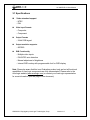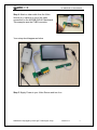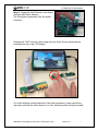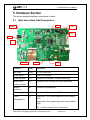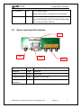
1
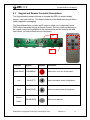
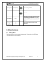
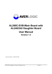
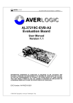
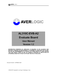
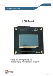
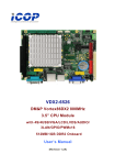
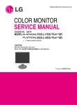
AL330B-EVB-A1-UserManual AL330B-EVB-A1 Digital LCD Display SOC Evaluation Board User Manual Version 1.0 INFORMATION FURNISHED BY AVERLOGIC IS BELIEVED TO BE ACCURATE AND RELIABLE. HOWEVER, NO RESPONSIBILITY IS ASSUMED BY AVERLOGIC FOR ITS USE, OR FOR ANY INFRINGEMENTS OF PATENTS, OR OTHER RIGHTS OF THIRD PARTIES THAT MAY RESULT FROM ITS USE. NO LICENSE IS GRANTED BY IMPLICATION OR OTHERWISE UNDER ANY PATENT OR PATENT RIGHTS OF AVERLOGIC. Document Number: 1-M-PAE033-0101 © 2008-2012 Copyright by AverLogic Technologies, Corp. Version 1.0 AL330B-EVB-A1-UserManual Amendments Date Version 2012-10-31 1.0 Comments Author Public Release Ken Liu Disclaimer THE CONTENTS OF THIS DOCUMENT ARE SUBJECT TO CHANGE WITHOUT NOTICE. AVERLOGIC TECHNOLOGIES RESERVES THE RIGHT TO MAKE CHANGES WITHOUT FURTHER NOTICE TO ANY PRODUCTS HEREIN TO IMPROVE RELIABILITY, FUNCTION OR DESIGN. AVERLOGIC DOES NOT ASSUME ANY LIABILITY ARISING OUT OF THE APPLICATION OR USE OF ANY PRODUCT OR CIRCUIT DESCRIBED HEREIN; NEITHER DOES IT CONVEY ANY LICENSE UNDER ITS PATENT RIGHTS, NOR THE RIGHTS OF OTHERS. CUSTOMERS ARE ADVISED TO CONSULT WITH AVERLOGIC OR ITS COMMERCIAL DISTRIBUTORS BEFORE ORDERING. © 2008-2012 Copyright by AverLogic Technologies, Corp. Version 1.0 AL330B-EVB-A1-UserManual TABLE OF CONTENTS 1. Introduction................................................................................................... 1 2. Package Contents ........................................................................................ 2 3. General Product Description ....................................................................... 3 3.1 Specifications ..................................................................................................................... 4 4. Quick Setup................................................................................................... 5 5. Hardware Section ......................................................................................... 8 5.1 Main board (back side) Descriptions ............................................................................... 8 5.2 Source input board Descriptions ..................................................................................... 9 5.3 Keypad and Remote Controller Descriptions................................................................. 10 6. Miscellaneous ............................................................................................. 11 6.1 Debug Mode .................................................................................................................. 11 © 2008-2012 Copyright by AverLogic Technologies, Corp. Version 1.1 AL330B-EVB-A1-UserManual 1. Introduction The AL330B EVB is an evaluation product using AverLogic chips to demonstrate a total solution for Small to Medium Digital LCD Display applications. This EVB product can accept multiple video inputs (Composite video and Components Video), which can then be displayed in high quality on an LCD Screen. The main component is the AL330B chip, a highly integrated Display SOC, containing a 3-Ch + 10-bit ADC, 2D Video Decoder, Deinterlacer, Scaler, Microcontroller, OSD, and TCON. The AL330B can support small to medium Digital TFT-LCD Panels and small to medium AMOLED Display Devices. This product contains 1 Mbit of serial flash for customizable boot and code storage. The AL330B is a multi-channel analog preprocessing circuit, which includes Source Selection; anti-aliasing filter; ADC, ACC (Auto-Clamp Control) and AGC (Auto-Gain Control); CGC (Clock Generation Circuit); digital multi-standard decoder containing chrominance and luminance separation from an adaptive 2D comb filter; brightness, contrast, hue and saturation control circuit; programmable horizontal and vertical scaler; image and sharpness enhancement processing; On-Screen-Display; programmable TCON; and a digital RGB signal output and more. AverLogic can also provide ISP Tools for development and a Converter board for adapting different types of display panels for use with the AL330 EVB. Please contact your representative for more information. © 2008-2012 Copyright by AverLogic Technologies, Corp. Version 1.0 1 AL330B-EVB-A1-UserManual 2. Package Contents The AL330B-EVB-A1 package contains the following components: A. Mainboard (with LCD display) G. Component (YPbPr) Cable B. Source Input Board H. Remote controller C. Keypad Board I. Source Input Board cable D. 12V Power Adapter J. Keypad Board cable E. AC Power Cord K. User Manual (not shown) F. CVBS Video Cable D G E A F C C B I J H If any components are missing or damaged, please contact your representative. Note: To test this product, you will need to provide a Video Source (e.g. camera, DVD player) with a YPbPr or CVBS connector. © 2008-2012 Copyright by AverLogic Technologies, Corp. Version 1.0 2 AL330B-EVB-A1-UserManual 3. General Product Description The AL330B-EVB-A1 is comprised of a Mainboard with an LCD Panel attached to one face of the board. Ribbon cables are used to attach a Source Input board and a Keypad board. The backside of the Mainboard contains ribbon cable connectors, a power connector, an on/off switch; it also contains several jumpers that will be explained later. Mainboard LCD Panel Source Input Board Keypad Board Power Connector Ribbon Cables connectors On/Off Switch Mainboard (backside) © 2008-2012 Copyright by AverLogic Technologies, Corp. Version 1.0 3 AL330B-EVB-A1-UserManual 3.1 Specifications Video standard support - NTSC - PAL Video Input Formats - Composite - Component Output Formats - 24-bit RGB signal Output resolution supports: - 800*480 EVB Functionality - Multiple video inputs - PAL/NTSC auto detection - Manual adjustment of brightness - Internal OSD overlay with programmable font for OSD display Note: Please be aware that this is an Evaluation product only and not all functional capabilities of AverLogic components are fully demonstrated. Please refer to the AverLogic website (www.averlogic.com) or contact your AverLogic representative for more information (see last page of this document). © 2008-2012 Copyright by AverLogic Technologies, Corp. Version 1.0 4 AL330B-EVB-A1-UserManual 4. Quick Setup This quick setup section will guide you through the AL330B-EVB-A1 setup. You will need to provide a video source with a CVBS or YPbPr (480i/576i) connection. In this quick guide, we will use a standard definition video camera as the example video source. Step 1: Attach the 4-wire Keypad board cable to the Mainboard and the Keypad board. The connectors will attach in one direction only; do not try to force the cable connector onto the board connector. Step 2: Attach the wider ribbon cable (Source Input board cable) to the Mainboard and the Source Input board. Step 3: Attach the Power Adaptor to the Mainboard. Attach the Power Cord to the Power Adaptor and then connect it to an electrical outlet with the appropriate voltage. © 2008-2012 Copyright by AverLogic Technologies, Corp. Version 1.0 5 AL330B-EVB-A1-UserManual Step 4: Attach a video cable from the Video Source (e.g. camera) to one of the video connectors on the AL330B-EVB-A1 Mainboard. This example uses the CVBS connector. Your setup should appear as below. Step 5: Supply Power to your Video Source and turn it on. © 2008-2012 Copyright by AverLogic Technologies, Corp. Version 1.0 6 AL330B-EVB-A1-UserManual Step 6: Toggle the On/Off switch on the board (located near Power Adapter). The ON position faces away from the power connector. Pressing the “SW5” then the video image from the Video Source should almost instantly show up on the LCD display. If no video displays, double check all of the video connectors, power connectors and make sure that the Video Source is, in fact, delivering video through the cable. © 2008-2012 Copyright by AverLogic Technologies, Corp. Version 1.0 7 AL330B-EVB-A1-UserManual 5. Hardware Section This section describes hardware components in detail. 5.1 Main board (back side) Descriptions JP1 CON3 JP6 JPIIC JP2 S1 JP3 CN1 SWA1 J1 Function Label Description DC Power CON3 DC 12V Power input Power Switch S1 Power On/Off Switch Panel connector CN1 Connector for Hannstar 7 inch panel (800*480) Source Input board connector JP2 Connects to JP4 connector on Source Input board. Keypad connector JP3 Connects to Keypad board. Reset key SWA1 Resets the AL330 and internal MCU. SSEL1 JP1 Jumper pins 1-2 for normal operations (slave address 0x34). Download pins Jumper pins 2-3 for programming mode (slave address 0x38). (Pin 1 is the pin closest to the J5 connector) © 2008-2012 Copyright by AverLogic Technologies, Corp. Version 1.0 8 AL330B-EVB-A1-UserManual IIC Connector JPIIC For IIC debug function. Please refer to SSEL1 for selecting IIC slave address. SPI connector J1 Connects to the ISP & Debug Tool PIN1=3.3V,PIN2=RXD,PIN3=TXD,PIN4=NC,PIN5=GND (PIN1 is the pin closest to SWA1) 5.2 Source input board Descriptions JP4 Y CON4 Pr Pb CON5 CON6 Function Label Description Reserved CON5 Reserved CVBS CON4 CVBS input Component Video CON4 Component video input Connector for the Mainboard JP4 Connects to JP2 connector on the Mainboard © 2008-2012 Copyright by AverLogic Technologies, Corp. Version 1.0 9 AL330B-EVB-A1-UserManual 5.3 Keypad and Remote Controller Descriptions The Keypad board contains buttons to navigate the OSD (on screen display menus – see next section). This board connects to the Mainboard using a ribbon cable (supplied in packaging). The Keypad board also contains an IR sensor to allow you to alternately issue OSD menu commands through a Remote Control. The only functional buttons on the remote control are highlighted in the picture below and are listed in the table that follows (all other buttons are non-functional). JP5 SW5 SW4 SW3 SW2 SW1 U11 Function Keypad Remote Description Power On/Off SW5(MENU) Used to turn on or turn off the panel. Left SW4(LEFT) Used to decrease values of brightness. Right SW3(RIGHT) Used to increase values of brightness. SW2(ENTER) Video source selector. Source Select © 2008-2012 Copyright by AverLogic Technologies, Corp. Version 1.0 10 AL330B-EVB-A1-UserManual Debug Mode SW1(BACK) Enter to Debug MODE. Reserved IR Receiver U11 Receives IR signals from the remote control to be relayed to the Mainboard. You must point the Remote Control at this sensor in order for the IR Receiver to receive the IR signals. Connector for the Mainboard JP5 Uses a ribbon cable to connect to the Mainboard. 6. Miscellaneous 6.1 Debug Mode This board can burn-in code or operate in debug mode. Please refer to the USB Debug Tool User Manual for more information. © 2008-2012 Copyright by AverLogic Technologies, Corp. Version 1.0 11 AL330B-EVB-A1-UserManual CONTACT INFORMATION AverLogic Technologies, Corp. E-Mail: [email protected] URL: http://www.averlogic.com © 2008-2012 Copyright by AverLogic Technologies, Corp. Version 1.0 12