1
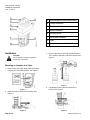
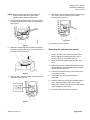
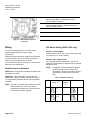
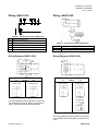
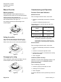
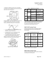
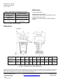
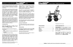
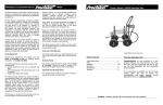
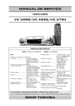
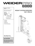
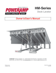
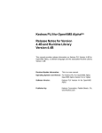
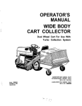
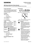
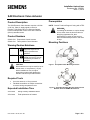
Installation Instructions
Document No. 129-561
June 11, 2014
SAX Electronic Valve Actuator
Product Description
The SAX Electronic Valve Actuator requires a 24 Vdc
or 24 Vac, Class 2, supply signal to control a
Flowrite™ 599 Series valve or a Siemens flanged,
Pressure Independent Control valve with a 3/4-inch
(20 mm) standard stroke.
Product Numbers
SAX61.03U
SAX81.03U
Proportional Control Actuator
Three-position Control Actuator
Prerequisites
NOTE: Consult Technical Support if using with a TEC.
WARNING:
If mounting the actuator to a valve already
in line, either close the shut-off valves in
the piping (upstream first, then
downstream) or switch off the pump to
allow the differential pressure in the valve
to drop.
Mounting Positions
Warning/Caution Notations
WARNING:
Personal injury or loss of life
may occur if you do not
follow a procedure as
specified.
Equipment damage or loss
of data may occur if you do
not follow a procedure as
specified.
CAUTION:
CAUTION:
Figure 1. Acceptable Indoor Mounting Positions.
SAX Actuators can only be used for hot or
chilled water, or low pressure (<15 psi)
steam installations. Use on higher
temperature systems will damage the
actuator and lead to premature failure.
Required Tools
•
4 mm hex wrench, or 10 mm wrench
•
Flat-blade screwdriver or Phillips screwdriver
to remove wiring compartment cover
Expected Installation Time
30 minutes
Wiring a factory-installed actuator
45 minutes
Field replacement of actuator
Item Number: 129-561, Rev. BA
Figure 2. Acceptable Outdoor Mounting Positions with
Weather Shield for NEMA 3R Protection.
Page 1 of 8
Document No. 129-561
Installation Instructions
June 11, 2014
A Manual adjuster (with slide switch)
B Wiring knockouts
C Position indication
D Status indication
E Housing cover
F Valve stem coupling
G Yoke
H Bonnet connection U-bracket
Installation
CAUTION:
Do not damage or scratch the polished
surface of the valve stem.
3. Pull the valve stem to the fully extended position.
Then, slide the actuator on the valve bonnet. See
Figure 5.
Mounting an Actuator to a Valve
1. Ensure stem connection plate in the Valve Stem
Coupling is in the OPEN position. See Figure 3.
Figure 5.
Figure 3.
4. Completely close the bonnet connection Ubracket. See Figure 6.
2. Open the bonnet connection U-bracket. See
Figure 4.
Figure 4.
Page 2 of 8
Figure 6.
Siemens Industry, Inc.
Document No. 129-561
Installation Instructions
June 11, 2014
NOTE: Position the actuator to accommodate the
wiring. Hold the actuator in place while
tightening the actuator U-bracket bolt.
8. Secure the stem connection plate by tightening the
bolt, using a 10 mm wrench (or 4 mm Allen
wrench). See Figure 10.
5. Tighten the U-bracket bolt using a 10 mm wrench
(or 4 mm Allen wrench) to 5 Nm (44 in-lbs) torque.
See Figure 7.
Figure 10.
The mounting is now complete.
Figure 7.
6. Rotate the manual adjuster clockwise to manually
extend the actuator shaft until it covers the head of
the valve stem See Figure 8.
Removing the actuator from a valve
1. Loosen the stem connection plate in the Valve
Stem Coupling by loosening the bolt, using a
10 mm wrench (or 4 mm Allen wrench).
2. Open the stem connection plate over the valve
stem.
3. Manually retract the actuator shaft by turning the
Manual Adjuster counterclockwise until it reveals
the head of the valve stem.
Figure 8.
7. Close the stem connection plate securely over the
valve stem. See Figure 9.
4. Loosen the U-bracket using a 10 mm wrench (or
4 mm Allen wrench).
5. Completely open the bonnet connection
U-bracket.
6. Push the valve stem to the fully retracted position.
Then, slide the actuator off the valve bonnet.
7. Remove the actuator from the valve, being careful
not to damage the valve stem.
8. Close the bonnet connection U-bracket.
Figure 9.
Siemens Industry, Inc.
Page 3 of 8
Document No. 129-561
Installation Instructions
June 11, 2014
A
C
Plug-in space for…
− Potentiometer ASZ7.5.. (SAX81.03U only) or
− Auxiliary switch ASC10.51.
Plug-in space for…
− Function module AZX61.1 (SAX61.03U only), or
− Auxiliary switch ASC10.51
LED (SAX61.03U only)
D
DIP Switches (SAX61.03U only)
E
Calibration Slot (SAX61.03U only)
F
Connection Terminals
B
Figure 11. SAX Actuator with Cover
Removed.
Wiring
DIP Switch Setting (SAX61.03U only)
Do not use autotransformers. Use earth ground
isolating step-down Class 2 power supply
transformers.
Switch 1: Control Signal
Determine supply transformer rating by summing total
VA of all actuators used. The maximum rating for a
Class 2 step-down transformer is 100 VA.
Select between 0 to 10 Vdc or 4 to 20 mA input signal
for terminal Y (0 to 10 Vdc default).
It is recommended that no more than 10 actuators are
powered by one transformer.
Switch 2: Flow Characteristic
Do not change the flow characteristic switch. The
proper flow characteristic is designed into the Flowrite
599 Series valve.
Parallel Control of Actuators
NOTE:
SAX81.0-3U -Three-position actuators must have their
own specific controller.
SAX61.03U - Up to 10 actuators can be driven in
parallel from a single controller output with a rating of
1 mA. Modulating actuators have an input impedance
of 100KΩ.
NOTE: Use either a Phillips head screwdriver or a flatblade screwdriver to remove the wiring
compartment housing cover for access to the
terminal block and DIP switches.
Changing the default setting will modify an
equal percentage valve to a linear flow
characteristic. When set to default, the flow
characteristic is determined by the valve
body.
Table 1. DIP Switch Settings.
Positioning
Position
Signal "Y"
Feedback
Flow Characteristic
"U"
0 to 10
Vdc
0 to 10 Vdc
Default
1)
ON
DC 4 to
0 to 10 Vdc
Modified
OFF
20 mA
1) Factory setting: All DIP switches are set to OFF.
Page 4 of 8
Siemens Industry, Inc.
Document No. 129-561
Installation Instructions
June 11, 2014
Wiring, SAX61.03U
Wiring, SAX81.03U
Figure 12. Connecting Terminals (SAX61.03U).
G0
G
Y
M
U
Z
System Neutral (SN)
System Potential (SP)
Positioning signal for 0 to 10 Vdc/4 to 20 mA
Measuring neutral
Position feedback 0 to 10 Vdc
Positioning signal forced control
Wiring Diagrams (SAX61.03U)
A
Accessories
and/or
1x ASC10.51
Auxiliary Switch
B
1x ASC10.51
Auxiliary Switch
Figure 13. Applications.
The wiring diagrams show all possible connections.
The application determines which connections are
used. A and B are optional auxiliary switches.
Figure 14. Connecting Terminals (SAX81.03U).
G
Y1
Y2
System potential (SP)
Positioning signal (actuator's stem extends)
Positioning signal (actuator's stem retracts)
Wiring Diagrams (SAX81.03U)
A
Accessories
and/or
1x ASC10.51
Auxiliary Switch
B
1x ASC10.51
Auxiliary Switch
or 1 x ASZ7.5/..
Potentiometer
Figure 15. Application.
The wiring diagrams show all possible connections.
The application determines which connections are
used.
Siemens Industry, Inc.
Page 5 of 8
Document No. 129-561
Installation Instructions
June 11, 2014
Manual Override
Commissioning and Operation
Manual operation
Function Check and Calibration
When pushing the manual adjuster down (1), it
engages and the actuator can be manually operated.
Mechanical Check
When turning the manual adjuster in a
clockwise/counterclockwise direction (2), the actuator’s
stem extends/retracts. See Figure 16.
Prior to making the function check, ensure that:
An overload protection prevents damage to the
manual adjuster.
• Actuator is mechanically connected to a Siemens
valve.
• Actuator is in Manual Operation mode.
The actuator can be operated with the help of the
Manual Adjuster.
Figure 16.
Setting the position
Upon actuation and locking the slide switch (see
Figure 17), the manual adjuster remains engaged.
When in this mode, do not turn the manual adjuster.
Manual Adjuster
Action
Actuator Response
Turning in clockwise
direction
Actuator’s stem
extends
Turning in counterclockwise direction
Actuator’s stem
retracts
NOTE: Ensure that the actuator’s and valve’s stems
are securely connected in all positions.
If the actuator is forced to travel beyond its
end positions, overload protection responds.
Electrical Check
Prior to making the function check, ensure that:
• Actuator is mechanically connected to a Siemens
valve.
• Actuator is in Automatic Operation mode.
Figure 17.
Disengaging the setting
When resetting the slide switch (see Figure 18), the
manual adjuster returns to Automatic Mode.
• Actuator and, if required, accessories are correctly
fitted and connected.
• Power is applied.
Calibration (SAX61.03U Only)
Calibration is required with modulating actuators, and
before the function check. Calibration must be
performed manually.
Prior to calibrating, ensure that:
• Actuator is properly connected to a valve.
• Housing cover is removed.
• Power is applied.
Figure 18.
Page 6 of 8
If required, calibration can be repeated any number of
times.
Siemens Industry, Inc.
Document No. 129-561
Installation Instructions
June 11, 2014
To initiate the calibration process insert a flat-blade
screwdriver into the calibration slot to short out the two
sides of the slot. See Figure 19.
Table 2. LED Indication and Status.
LED
Indication
Operating state
On
Automatic mode
Calibration
Green
Blinking
In manual mode
On
Red
Blinking
Figure 19. Step 1—Bridge contact.
During calibration, the actuator detects the valve’s end
positions and files the exact stroke in its internal
memory. Calibration takes place in three phases:
Off
Off
Calibration error
Detection of
foreign object
No power or
electronics faulty
Remarks,
troubleshooting
Normal operation
Wait until calibration is
finished
(then green or red light)
Manual adjuster in
MAN position
Start calibration again
Check valve / actuator
Check operating
voltage
If the actuator does not detect the second end position
within an appropriate stroke range (max. 25 mm), the
first end stop will be adopted and the actuator
operates with a working range of 20 mm.
SAX61.03U Function Check
•
Actuator drives to H0 (1), retracting actuator stem.
Detection of upper end position.
•
Actuator drives to H100 (2), extending actuator
stem. Detection of lower end position.
Perform the function check for modulating actuators
after calibration with a point test according to the
following table:
Table 3. Modulating Function Check.
Connection
Terminals
•
The detected values are stored (3). Then the
actuator follows the applied control signal.
Observe the status indication (LED) during and after
calibration. See Figures Figure 20 and Table 2.
Y
Y
6V
13.6 mA
5V
12 mA
“Z” connected to
“G”
Figure 20. Step 2—Check LED.
Actuator
Response
Position
Feedback
(U)
Actuator’s stem
extends (60%)
6V
Actuator’s stem
retracts (50%)
5V
Actuator’s stem
extends to 100%
10V
“Z” connected to
Actuator’s stem
0V
“G0”
retracts to 0%
After successful completion of the function check, the
actuator is ready for normal operation.
SAX81.03U Function Check
Perform the function check for three-position actuators
according to the following table:
Siemens Industry, Inc.
Page 7 of 8
Document No. 129-561
Installation Instructions
June 11, 2014
References
Table 4. Three-Position (Floating) Function Check.
Connection Terminals
Actuator Response
Voltage at Y1
Actuator’s stem extends
Voltage at Y2
Actuator’s stem retracts
Technical Instructions:
Flowrite 599 Series 155-506
SAX Electronic Valve Actuator Proportional Control
Flowrite 599 Series 155-507
SAX Electronic Valve Actuator 3-position (floating)
Control
No voltage at Y1 and
Actuator’s stem maintains
Y2
the position
After successful completion of the function check, the
actuator is ready for normal operation.
Dimensions
Product
Numbers
SAX61.03U
SAX81.03U
With ASK39.1
A
B
C
C1
C2
D
E
►
►►
Weight
lbs (kg)
9.53
(242)
10.51
(267)
4.88
(124)
6.06
(154)
5.91
(150)
11.81
(300)
2.68
(68)
7.87
(200)
3.23
(82)
3.94
(100)
3.15
(80)
3.94
(100)
3.94
(100)
7.87
(200)
–
–
–
–
4.1
(1.85)
4.6
(2.08)
Figure 21. SAX Dimensions in Inches (Millimeters).
Information in this publication is based on current specifications. The company reserves the right to make changes in specifications and models as
design improvements are introduced. Flowrite is a registered trademark of Siemens Industry, Inc. Other product or company names mentioned
herein may be the trademarks of their respective owners. © 2014 Siemens Industry, Inc.
Siemens Industry, Inc.
Building Technologies Division
1000 Deerfield Parkway
Buffalo Grove, IL 60089
USA
+ 1 847-215-1000
Your feedback is important to us. If you have
comments about this document, please send them
to [email protected]
Document No. 129-561
Printed in the USA
Page 8 of 8