1
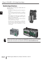
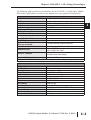
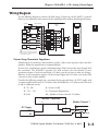
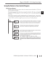
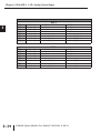
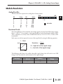
Chapter 3: F0-04AD-1 4-Ch. Analog Current Input
DL06 Pointer Method
1
2
3
4
5
6
7
8
9
10
11
12
13
14
A
B
C
D
3–10
Use the special V–memory table below as a guide to setup the storage pointer in the following
example for the DL06. Slot 1 is the left most option slot. The CPU will examine the pointer
values at these locations only after a mode transition.
Analog Input Module
DL06 Special V-memory Locations
Slot No.
No. of Channels
Input Pointer
1
V700
V701
2
V710
V711
3
V720
V721
4
V730
V731
The F0–04AD–1 can be installed in any available DL06 option slot. Using the example
program from the previous page, but changing the V–memory addresses, the ladder diagram
below shows how to setup these locations with the module installed in slot 1 of the DL06. Use
the above table to determine the pointer values if locating the module in any of the other slot
locations. Place this rung anywhere in the ladder program or in the initial stage if you are using
stage programming instructions.
Like the DL05 example, this logic is all that is required to read the analog input data into Vmemory locations. Once the data is in V-memory you can perform mathematical calculations
with the data, compare the data against preset values, and so forth. V2000 is used in the example
but you can use any user V-memory location.
SP0
LD
K400
Loads a constant that specifies the number of channels to scan and the
data format. The upper byte selects the data format (i.e. 0=BCD,
8=Binary) and the number of channels (set to 4 for the F0–04AD–1).
- or LD
K8400
The binary format can be used for displaying data on some
operator interface units and the DL06 LCD display. The DL06
PLCs support binary math functions.
OUT
V700
Special V-memory location assigned to the first option slot contains the
data format and the number of channels to scan.
LDA
O2000
This loads an octal value for the first V-memory location that will be used
to store the incoming data. For example, the O2000 entered here would
designate the following addresses.
Ch1 – V2000, Ch2 – V2001, Ch3 – V2002, Ch 4 – V2003
OUT
V701
The octal address (O2000) is stored here. V701 is assigned to the
first option slot and acts as a pointer, which means the CPU will use the
octal value in this location to determine exactly where to store the
incoming data.
DL05/06 Option Modules User Manual; 7th Ed. Rev. A, 08/11