1
StorageTek SL8500
User Guide
E20869-07
February 2014
StorageTek SL8500 User Guide
E20869-07
Copyright © 2013, 2014, Oracle and/or its affiliates. All rights reserved.
This software and related documentation are provided under a license agreement containing restrictions on
use and disclosure and are protected by intellectual property laws. Except as expressly permitted in your
license agreement or allowed by law, you may not use, copy, reproduce, translate, broadcast, modify, license,
transmit, distribute, exhibit, perform, publish, or display any part, in any form, or by any means. Reverse
engineering, disassembly, or decompilation of this software, unless required by law for interoperability, is
prohibited.
The information contained herein is subject to change without notice and is not warranted to be error-free. If
you find any errors, please report them to us in writing.
If this is software or related documentation that is delivered to the U.S. Government or anyone licensing it
on behalf of the U.S. Government, the following notice is applicable:
U.S. GOVERNMENT END USERS: Oracle programs, including any operating system, integrated software,
any programs installed on the hardware, and/or documentation, delivered to U.S. Government end users
are "commercial computer software" pursuant to the applicable Federal Acquisition Regulation and
agency-specific supplemental regulations. As such, use, duplication, disclosure, modification, and
adaptation of the programs, including any operating system, integrated software, any programs installed on
the hardware, and/or documentation, shall be subject to license terms and license restrictions applicable to
the programs. No other rights are granted to the U.S. Government.
This software or hardware is developed for general use in a variety of information management
applications. It is not developed or intended for use in any inherently dangerous applications, including
applications that may create a risk of personal injury. If you use this software or hardware in dangerous
applications, then you shall be responsible to take all appropriate fail-safe, backup, redundancy, and other
measures to ensure its safe use. Oracle Corporation and its affiliates disclaim any liability for any damages
caused by use of this software or hardware in dangerous applications.
Oracle and Java are registered trademarks of Oracle and/or its affiliates. Other names may be trademarks of
their respective owners.
Intel and Intel Xeon are trademarks or registered trademarks of Intel Corporation. All SPARC trademarks
are used under license and are trademarks or registered trademarks of SPARC International, Inc. AMD,
Opteron, the AMD logo, and the AMD Opteron logo are trademarks or registered trademarks of Advanced
Micro Devices. UNIX is a registered trademark of The Open Group.
This software or hardware and documentation may provide access to or information on content, products,
and services from third parties. Oracle Corporation and its affiliates are not responsible for and expressly
disclaim all warranties of any kind with respect to third-party content, products, and services. Oracle
Corporation and its affiliates will not be responsible for any loss, costs, or damages incurred due to your
access to or use of third-party content, products, or services.
Contents
Preface ............................................................................................................................................................... xiii
Documentation Accessibility ...................................................................................................................
Conventions ...............................................................................................................................................
xiii
xiii
Summary of Changes ............................................................................................................................... xv
1 Introduction
2 StorageTek Library Console
SLConsole Modes.....................................................................................................................................
Download the SLConsole Media Pack.................................................................................................
SLConsole Screen Display .....................................................................................................................
Modifying the Screen Layout ...........................................................................................................
Synchronizing the Display with the Controller Database............................................................
Library Configuration Updates ................................................................................................
SLConsole Help ........................................................................................................................................
SLConsole Reports...................................................................................................................................
Report Types .......................................................................................................................................
User Management ....................................................................................................................................
User IDs ...............................................................................................................................................
Passwords............................................................................................................................................
Change a User Password ...........................................................................................................
SLConsole Login ................................................................................................................................
Automatic Logout .......................................................................................................................
SLConsole Logoff ...............................................................................................................................
Web-launched SLConsole ......................................................................................................................
Security Considerations ....................................................................................................................
Client Requirements ..........................................................................................................................
Log in to the Web-launched SLConsole..........................................................................................
Log in to the Web-launched SLConsole Using an Icon ................................................................
Standalone SLConsole ............................................................................................................................
Security Considerations ....................................................................................................................
Installation Requirements .................................................................................................................
Install the Standalone SLConsole ....................................................................................................
Log in to the Standalone SLConsole................................................................................................
2-1
2-1
2-2
2-3
2-3
2-3
2-3
2-3
2-4
2-4
2-4
2-4
2-4
2-5
2-5
2-5
2-5
2-5
2-5
2-6
2-7
2-7
2-7
2-7
2-7
2-8
iii
Local Operator Panel ...............................................................................................................................
Virtual Keypad ...................................................................................................................................
Log in to the Local Operator Panel..................................................................................................
Touch Screen Calibration ..................................................................................................................
Re-calibrate the Local Operator Panel .....................................................................................
Reset the Local Operator Panel Calibration ............................................................................
2-8
2-8
2-8
2-9
2-9
2-9
3 Hardware Activation Files
Oracle Hardware Activation Files.........................................................................................................
Legacy Hardware Activation Files ..................................................................................................
Hardware Activation File Installation Overview...............................................................................
Download a New Hardware Activation File.......................................................................................
Install a New Hardware Activation File on the Target Library ......................................................
Delete a Hardware Activation File........................................................................................................
Display Current Hardware Activation Files .......................................................................................
Display the Feature Audit Log...............................................................................................................
3-1
3-1
3-1
3-2
3-2
3-3
3-3
3-3
4 Capacity Activation
Configuring Active Capacity .................................................................................................................
Default Configuration .......................................................................................................................
Customized Configuration ...............................................................................................................
Guidelines for Customized Activation ....................................................................................
Activating Capacity in Non-partitioned Libraries.............................................................................
Activating Capacity in HLI Hosted Libraries ................................................................................
SLConsole Capacity Icons ......................................................................................................................
Capacity Activation using SLConsole..................................................................................................
Active Cell Configuration - Single Library.....................................................................................
Design the Active Cells Configuration ....................................................................................
Display Active Cells Report ......................................................................................................
Active Cell Configuration - Library Complex ...............................................................................
Design the Active Cells Configuration ....................................................................................
4-1
4-1
4-1
4-1
4-2
4-2
4-2
4-2
4-3
4-3
4-3
4-3
4-4
5 Library Partitioning
Activated Capacity and Partitions.........................................................................................................
Hosts and Partitions.................................................................................................................................
Shared Resources - CAPs ..................................................................................................................
Planning and Preparations .....................................................................................................................
Verifying the Physical Configuration of a Partition......................................................................
Resolving Orphaned Cartridges ......................................................................................................
Maximizing Library Performance .........................................................................................................
Library Partitioning .................................................................................................................................
Instructions Tab - Prepare for Partitioning ....................................................................................
Summary Tab - Add or Delete Partition Definitions ....................................................................
Add a Partition Definition .........................................................................................................
Delete a Partition Definition......................................................................................................
Design Tab - Allocate and Verify Resources in Partitions ...........................................................
iv
5-1
5-2
5-2
5-2
5-2
5-3
5-3
5-3
5-3
5-4
5-4
5-4
5-5
Commit Tab - Commit Partitioning Changes ................................................................................ 5-6
Reports Tab - Single Library Only - Generate Partitioning Reports........................................... 5-6
CAP Operation - Override a CAP Reservation................................................................................... 5-6
6 Redundant Electronics
Requirements ............................................................................................................................................
Redundant Electronics Overview .........................................................................................................
Automatic Failover ............................................................................................................................
Manual Failover .................................................................................................................................
Connections.........................................................................................................................................
Firmware Upgrades ...........................................................................................................................
Controller Card Status.............................................................................................................................
LEDs .....................................................................................................................................................
SLConsole Status ................................................................................................................................
Display Redundant Electronics Information......................................................................................
Manual Redundant Electronics Switch................................................................................................
6-1
6-1
6-2
6-2
6-2
6-2
6-3
6-3
6-3
6-3
6-4
7 Library Management
Library and Device Status Overview ...................................................................................................
Health Status of a Device ..................................................................................................................
Communication Status ......................................................................................................................
Health Status of the Library..............................................................................................................
Upgrade Library Firmware .....................................................................................................................
Download Code to the Library Controller .....................................................................................
Activate Code on the Library Controller ........................................................................................
Display Library Information..................................................................................................................
Display Library Status .......................................................................................................................
Display Library Properties................................................................................................................
Library Reports...................................................................................................................................
Search a Library Report..............................................................................................................
Save Library Report Data to a File............................................................................................
Display Library Events Statistics ..............................................................................................
Display Library Power Supply Information ..................................................................................
Generate Library Diagnostic Files ........................................................................................................
Transfer the Library MIB File ...........................................................................................................
Generate and Transfer the Library Log Snapshot File..................................................................
Clear Library Status Alerts .....................................................................................................................
Perform a Library Self-Test ....................................................................................................................
Reboot the Library ...................................................................................................................................
Place the Library Online or Offline......................................................................................................
Place the Library Offline ...................................................................................................................
Bring the Library Online ...................................................................................................................
Bring the Drives Online.....................................................................................................................
Audits .........................................................................................................................................................
Physical Audit ....................................................................................................................................
Audit the Entire Library.............................................................................................................
7-1
7-1
7-1
7-2
7-2
7-2
7-3
7-3
7-3
7-4
7-4
7-4
7-4
7-4
7-5
7-5
7-5
7-5
7-6
7-6
7-7
7-7
7-7
7-8
7-8
7-8
7-9
7-9
v
Audit a Range of Cells................................................................................................................ 7-9
Verified Audit.................................................................................................................................. 7-10
8 CAP Management
CAP Modes ................................................................................................................................................
Recommendations for CAP Use ............................................................................................................
Maximizing Library Performance ...................................................................................................
Display CAP Information.......................................................................................................................
Change CAP Online/Offline Status ....................................................................................................
Lock/Unlock a CAP ..................................................................................................................................
Perform CAP Self-test .............................................................................................................................
8-1
8-2
8-2
8-2
8-2
8-3
8-3
9 Drive Management
Maximizing Library Performance .........................................................................................................
Drive Cleaning .........................................................................................................................................
Host-Managed Drive Cleaning ........................................................................................................
Display Drive Information.....................................................................................................................
Display the Drive and Drive Media Reports ......................................................................................
Configure the Drive Tray Serial Numbers..........................................................................................
Change a Drive Online/Offline Status ................................................................................................
Perform a Drive Self Test .......................................................................................................................
9-1
9-1
9-2
9-2
9-3
9-3
9-4
9-4
10 Cartridge Management
Cartridge Types .....................................................................................................................................
Cartridge Labels ..............................................................................................................................
Maximizing Library Performance ......................................................................................................
Display Cartridge Information...........................................................................................................
Locating Cartridges ...............................................................................................................................
Locate a Cartridge by vol-id ..........................................................................................................
Locate a Cartridge by Address......................................................................................................
Moving Cartridges (Recovery Moves)...............................................................................................
Move a Cartridge by Vol-id or Specified Location.....................................................................
Entering Cartridges ...............................................................................................................................
Ejecting Cartridges................................................................................................................................
Import/Export Diagnostic Cartridges ................................................................................................
Import Diagnostic Cartridges........................................................................................................
Export Diagnostic Cartridges ........................................................................................................
Cartridge Handling ...............................................................................................................................
Inspecting a Cartridge ....................................................................................................................
Cleaning the Cartridge Exterior....................................................................................................
Storing Cartridges ...........................................................................................................................
10-1
10-1
10-2
10-2
10-2
10-2
10-3
10-3
10-3
10-4
10-5
10-6
10-6
10-6
10-7
10-7
10-7
10-8
11 Media Validation
Drive Pool ............................................................................................................................................... 11-1
Validation Types ................................................................................................................................... 11-1
Stopping Validation ............................................................................................................................. 11-2
vi
Media Validation Tasks.......................................................................................................................
Slot Selection Tab - Add or Remove Drives from Media Validation Drive Pool...................
Add Drives to the Pool............................................................................................................
Remove Drives from the Pool ................................................................................................
Media Validation Tab - Perform Cartridge Validation .............................................................
Validate a Cartridge.................................................................................................................
Stop a Validation in Progress .................................................................................................
11-2
11-2
11-2
11-3
11-4
11-4
11-4
12 Robot and Safety Door Management
Safety Door Overview ..........................................................................................................................
Display Safety Door Information ......................................................................................................
HandBots Overview..............................................................................................................................
Fast Load Feature ............................................................................................................................
Robot Initialization .........................................................................................................................
Display Robot Information .................................................................................................................
Change Robot Online/Offline Status................................................................................................
Perform a Robot Self-Test ...................................................................................................................
Robot Diagnostic Moves......................................................................................................................
Define a Diagnostic Move..............................................................................................................
Manage Diagnostic Move Definitions..........................................................................................
Save a Diagnostic Move .................................................................................................................
Start a Diagnostic Move .................................................................................................................
Monitor and Control Open Diagnostic Moves ...........................................................................
12-1
12-1
12-1
12-2
12-2
12-2
12-2
12-3
12-3
12-4
12-5
12-5
12-5
12-6
13 Elevators and Pass-Thru Ports
Maximizing Library Performance ......................................................................................................
PTP Installation .....................................................................................................................................
Display Elevator Information .............................................................................................................
Display Pass-Thru Port Information .................................................................................................
13-1
13-1
13-2
13-2
14 SLConsole Diagnostics and Utilities
Library and Device Self-tests..............................................................................................................
Diagnostic Support Information ........................................................................................................
Troubleshooting ....................................................................................................................................
Library Events ........................................................................................................................................
Event Monitors ................................................................................................................................
Event Codes Reference ...................................................................................................................
Activity Code............................................................................................................................
Result Code ...............................................................................................................................
Severity ......................................................................................................................................
Request Identifier.....................................................................................................................
Create an Event Monitor ......................................................................................................................
Display an Event Monitor..............................................................................................................
Spool Event Monitor Data to a File ..............................................................................................
Display Multiple Monitors ............................................................................................................
Display Device Status or Result Code ..............................................................................................
14-1
14-1
14-2
14-3
14-3
14-3
14-3
14-4
14-4
14-5
14-5
14-5
14-5
14-5
14-6
vii
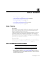
15 Manual Operation
Modes of Operation ..............................................................................................................................
Safety Precautions when Entering the Library................................................................................
Emergency Robotics Stop Switch..................................................................................................
Moving a Robot ...............................................................................................................................
Entering or Exiting the Library...........................................................................................................
Enter the Library .............................................................................................................................
Exit the Library ...............................................................................................................................
Powering the Library On or Off .........................................................................................................
Power Off the Library.....................................................................................................................
Power On the Library .....................................................................................................................
Manual Mount and Dismount Operations ......................................................................................
Manually Mount a Cartridge in a Drive ......................................................................................
Dismount a Cartridge from a Drive .............................................................................................
Service Safety Door Operation ...........................................................................................................
Left Maintenance Area ...................................................................................................................
Right Maintenance Area.................................................................................................................
15-1
15-1
15-2
15-2
15-3
15-3
15-4
15-4
15-4
15-5
15-5
15-5
15-6
15-6
15-6
15-6
A Command Line Interface Reference
audit ...........................................................................................................................................................
capCommand............................................................................................................................................
cleaning .....................................................................................................................................................
config .........................................................................................................................................................
date .............................................................................................................................................................
drive ...........................................................................................................................................................
hwActivation ............................................................................................................................................
mediaValidation ......................................................................................................................................
network......................................................................................................................................................
partition...................................................................................................................................................
reControl .................................................................................................................................................
snmp.........................................................................................................................................................
ssh.............................................................................................................................................................
time...........................................................................................................................................................
traceRoute ...............................................................................................................................................
version .....................................................................................................................................................
whereAmi................................................................................................................................................
A-1
A-3
A-3
A-6
A-7
A-7
A-8
A-8
A-9
A-11
A-11
A-12
A-12
A-12
A-12
A-13
A-13
B Library Addressing
Structural Elements.................................................................................................................................
Library Walls, Arrays, and Slots .....................................................................................................
Library Storage Module (LSM) .......................................................................................................
Library Complex HLI Numbering ..........................................................................................
Panels and Columns .........................................................................................................................
Internal Firmware Addressing Scheme ..............................................................................................
HLI-PRC ....................................................................................................................................................
Comparison of the Addressing Schemes............................................................................................
viii
B-1
B-1
B-1
B-1
B-2
B-3
B-4
B-6
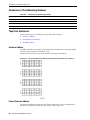
Tape Drive Addresses ............................................................................................................................
Hardware Address............................................................................................................................
Internal Firmware Address .............................................................................................................
HLI-PRC Address .............................................................................................................................
Drive Numbering Comparison .......................................................................................................
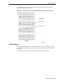
Internal Firmware Addresses of a Component ................................................................................
Cartridge Access Ports .....................................................................................................................
Pass-thru Mechanisms......................................................................................................................
Elevators .............................................................................................................................................
HandBots ..........................................................................................................................................
B-6
B-6
B-6
B-7
B-8
B-9
B-9
B-9
B-9
B-10
C Controlling Contaminants
Environmental Contaminants...............................................................................................................
Required Air Quality Levels .................................................................................................................
Contaminant Properties and Sources ..................................................................................................
Operator Activity ..............................................................................................................................
Hardware Movement .......................................................................................................................
Outside Air.........................................................................................................................................
Stored Items .......................................................................................................................................
Outside Influences ............................................................................................................................
Cleaning Activity ..............................................................................................................................
Contaminant Effects ...............................................................................................................................
Physical Interference.........................................................................................................................
Corrosive Failure...............................................................................................................................
Shorts ..................................................................................................................................................
Thermal Failure .................................................................................................................................
Room Conditions.....................................................................................................................................
Exposure Points .......................................................................................................................................
Filtration....................................................................................................................................................
Positive Pressurization and Ventilation .............................................................................................
Cleaning Procedures and Equipment..................................................................................................
Daily Tasks .........................................................................................................................................
Weekly Tasks .....................................................................................................................................
Quarterly Tasks .................................................................................................................................
Biennial Tasks ....................................................................................................................................
Activity and Processes ..........................................................................................................................
C-1
C-1
C-2
C-3
C-3
C-3
C-3
C-3
C-3
C-4
C-4
C-4
C-4
C-4
C-4
C-6
C-6
C-7
C-8
C-8
C-8
C-9
C-9
C-10
Glossary
Index
ix
x
List of Figures
2–1
15–1
15–2
15–3
B–1
B–2
B–3
B–4
B–5
B–6
B–7
SLConsole Screen Layout .......................................................................................................... 2-2
Emergency Robotic Stop Switch ............................................................................................ 15-2
Moving the HandBot ............................................................................................................... 15-3
AC PDU ..................................................................................................................................... 15-5
Pass-thru Port Planning Example............................................................................................ B-2
Internal Firmware Addressing Scheme .................................................................................. B-4
HLI-PRC Addressing Scheme .................................................................................................. B-5
Physical Hardware Numbering of Tape Drive (viewed from rear of library).................. B-6
Tape Drive Internal Firmware Addressing (viewed from front of library) ...................... B-7
Tape Drive HLI-PRC Addressing (viewed from front of library) ...................................... B-8
Comparison (viewed from front of library) ........................................................................... B-8
xi
List of Tables
2–1
4–1
4–2
6–1
6–2
7–1
11–1
11–2
12–1
12–2
14–1
B–1
B–2
C–1
C–2
xii
Virtual Keypad Buttons ............................................................................................................ 2-8
Single Library Capacity Icons .................................................................................................. 4-2
Library Complex Capacity Icons ............................................................................................. 4-2
LED Status Indicators................................................................................................................ 6-3
SLConsole Controller Card Statuses ....................................................................................... 6-3
Status Indicators......................................................................................................................... 7-1
Media Validation Types......................................................................................................... 11-2
Status Indicators for Drive Slots ........................................................................................... 11-3
Diagnostic Moves Options .................................................................................................... 12-5
Status Indicators for Moves................................................................................................... 12-6
Controls for Displaying Multiple Monitors ........................................................................ 14-5
Panel Numbering ...................................................................................................................... B-5
Comparison of Addressing Schemes ..................................................................................... B-6
Filtration Percentages ............................................................................................................... C-7
Cleaning Schedule for Data Center ........................................................................................ C-8
Preface
This document is intended for technical personnel using the SL8500 library, including
administrators and operators. This document assumes the reader is already familiar
with the SL8500 library modules and components. For introductory and planning
information, see the SL8500 Systems Assurance Guide on OTN at:
http://www.oracle.com/technetwork/documentation/tape-storage-curr-187744.h
tml
Documentation Accessibility
For information about Oracle's commitment to accessibility, visit the Oracle
Accessibility Program website at
http://www.oracle.com/pls/topic/lookup?ctx=acc&id=docacc.
Access to Oracle Support
Oracle customers have access to electronic support through My Oracle Support. For
information, visit http://www.oracle.com/pls/topic/lookup?ctx=acc&id=info or
visit http://www.oracle.com/pls/topic/lookup?ctx=acc&id=trs if you are hearing
impaired.
Conventions
The following text conventions are used in this document:
Convention
Meaning
boldface
Boldface type indicates graphical user interface elements associated
with an action, or terms defined in text or the glossary.
italic
Italic type indicates book titles, emphasis, or placeholder variables for
which you supply particular values.
monospace
Monospace type indicates commands within a paragraph, URLs, code
in examples, text that appears on the screen, or text that you enter.
xiii
xiv
Summary of Changes
February 2014
Updated list of supported operating systems for SLConsole.
October 2013
Updates for version FRS_8.31 and SLConsole 6.25 include:
■
Support for T10000D drives.
■
Media validation (see Chapter 11, "Media Validation")
■
Partitioning in a library complex (see Chapter 5, "Library Partitioning")
■
Added CLI commands (see Appendix A, "Command Line Interface Reference").
xv
xvi
1
Introduction
1
Oracle's StorageTek SL8500 Modular Library System is an enterprise storage solution
that provides fully automated tape-cartridge storage and retrieval. This document
provides library and device management guidelines, and detailed instructions on
using StorageTek Library Console (SLConsole).
Not all features described in this document are available on libraries running earlier
firmware versions. For a description of features available with a particular firmware
release, refer to the firmware release notes or contact an Oracle representative.
For more information related to the SL8500 library, see the following documents on the
Oracle Technical Network (OTN) at:
http://www.oracle.com/technetwork/documentation/tape-storage-curr-187744.h
tml
■
■
SL8500 Systems Assurance Guide - overview of the library and installation planning
guide
SL8500 Host Connectivity Guide - networking information on Dual TCP/IP, Multi
TCP/IP, redundant electronics, and partitioning
■
SL8500 SNMP Reference Guide - SNMP information
■
Library management software documentation:
■
ACSLS Administrator’s Guide
■
ELS System Programmer's Guide
Introduction 1-1
1-2 StorageTek SL8500 User Guide
2
StorageTek Library Console
2
Oracle’s StorageTek Library Console (SLConsole) is a Java-based software application
that provides a graphical user interface (GUI) for monitoring and managing the
SL8500 library. You can perform the following activities with the SLConsole:
■
View and modify status and properties of the library and associated devices
(drives, CAP, robot, and elevators)
■
Perform an audit, self-test, or diagnostic move
■
Locate or move a cartridge
■
Display library logs, status messages, error explanations, context-sensitive help
■
Download new library firmware while the library is in operation
SLConsole Modes
Throughout this document you can perform the procedures using any SLConsole
mode, unless otherwise noted.
■
"Local Operator Panel" on page 2-8
■
"Web-launched SLConsole" on page 2-5
■
"Standalone SLConsole" on page 2-7
Download the SLConsole Media Pack
The Media Pack includes the web-launched SLConsole server, web-launched
SLConsole client, and the standalone SLConsole.
1.
Go to the Oracle Software Delivery Cloud at:
http://edelivery.oracle.com/
2.
Click Sign In/Register. Sign in or register.
3.
On the Terms & Restrictions screen, read the License Agreement and Export
Restrictions, and select the check boxes to indicate your acceptance. Click
Continue.
4.
On the Media Pack Search screen:
a.
In the Select a Product Pack list, select Oracle StorageTek Products.
b.
In the Platform list, select Generic Platform.
c.
Click Go.
StorageTek Library Console 2-1
SLConsole Screen Display
5.
Select the SLConsole version to download, click Continue.
6.
To review the download instructions, click Readme. Optionally, use the View
Digest button to verify the MD5 and SHA-1 digests of the download files.
7.
Verify the SLConsole version is correct, click Download.
8.
Save the file.
9.
Extract the media pack to the desired location.
SLConsole Screen Display
Figure 2–1 SLConsole Screen Layout
Callout
Component Name
Description
1
Menu bar — includes
the Tools Menu and the
Help Menu
Tools — access to the SLConsole utilities
2
Title bar
Displays the title of the current screen or utility.
3
Function tabs
Identifies the available functions for a screen.
4
Options bar
Contains buttons related to the active utility. Always includes the Help
button (?).
5
Work area
Location of the screen data.
2-2 StorageTek SL8500 User Guide
Help — access to the help system and identifies the SLConsole version
SLConsole Reports
Callout
Component Name
Description
6
Library health indicator
Identifies the library connected to SLConsole, and displays library health.
7
UserID indicator
Displays the user ID currently logged in to SLConsole.
8
Server communication
health indicator
Displays a graphical heartbeat monitor indicating the state of server
communication health.
9
Navigation tree
Lists the devices included in the library.
Modifying the Screen Layout
■
■
■
To sort a column: Click the heading of the column. The initial sort is in ascending
order. Click the heading again to switch between ascending and descending order.
To arrange the columns: Click and drag a column heading horizontally to any
position in the heading row.
To resize the columns: Click the border of the column heading and drag it left or
right to change the column width.
Synchronizing the Display with the Controller Database
SLConsole receives library configuration data from the library controller.
Configuration data may be unavailable if you log in to SLConsole before the library is
fully initialized. Exit and log in again after initialization. Additionally, configuration
data displayed during an audit may not be accurate until the audit completes.
Library Configuration Updates
SLConsole displays the most recently saved data from the library controller database.
When the configuration changes (such as a drive is taken offline, or cartridges are
added/removed), synchronize SLConsole by clicking the Refresh button.
Multiple users can access the library simultaneously. Coordinate with other library
users when making major modifications to the configuration (such as adding modules,
defining partitions, and so on) to prevent conflicts.
In SLConsole, no changes are made to the library controller database until you click
the Apply button.
SLConsole Help
The SLConsole help displays information about SLConsole utility.
■
■
To display context-sensitive help for the current SLConsole screen, click the ?
button in the Options bar.
To display general help information, click Help > Contents in the Menu bar.
SLConsole help uses JavaHelp. For information about the JavaHelp interface, see:
http://docs.oracle.com/cd/E19253-01/819-0913/
SLConsole Reports
SLConsole reports provide information on the library and its associated devices,
events, and tape cartridges. You can use the reports to monitor library activity and
identify potential problems. See "Library Reports" on page 7-4 for report procedures.
StorageTek Library Console 2-3
User Management
Running multiple instances of SLConsole on the same
workstation can cause inconsistent data on reports. Only one user per
workstation should produce SLConsole reports, unless all instances of
the SLConsole are the same version.
Note:
Report Types
■
Log: Detailed system event logs
■
Statistics: Statistical information on library operations
■
Status Detail: Details on the status of the library and associated devices, such as
CAPs, drives, and robots
■
Status Summary: Summary information on the status of the library and devices
■
Version: Details about library hardware and software versions
User Management
To access SLConsole you must have a valid user ID and password. Only one user at a
time can log in to the local operator panel, but any number of users can log in to the
standalone or web-launched SLConsole.
User IDs
The user ID controls user authorization. Each user ID is assigned a set of permissions,
which determines access to utilities within SLConsole. There are a fixed set of user IDs
at each site:
■
admin: customer administrator
■
service: Oracle support representative
■
oem: third-party field service technician
Passwords
The library administrator must activate the admin user ID with the first 8 characters of
a one-time use activation password provided by an Oracle support representative.
After logging in with the activation password, the administrator should change the
admin user ID password to ensure system security.
For details about this process, Oracle representatives can refer to the SL8500 Installation
Guide.
Change a User Password
1.
Log in to the SLConsole using the account you want to modify.
2.
Select Tools > User Mgmt
3.
On the navigation tree, expand the Permanent folder. Select the current user
account
4.
Complete the following fields: Current Password, New Password, and Retype
Password.
5.
Click Modify.
2-4 StorageTek SL8500 User Guide
Web-launched SLConsole
SLConsole Login
When you log into SLConsole you must provide.
■
■
■
User ID: SLC_login. SLConsole user ID.
Password: password. Password assigned to this user ID. (Beginning with
SLConsole 4.50 password must be between 5-8 characters.)
Library: library_ID. Either the IP address or DNS alias of the library to which to
connect.
Automatic Logout
After six hours (default), the SLConsole session will expire. The system allows four
attempts to log back in, the logs the user ID out. To log in, return to the main login
screen.
SLConsole Logoff
Before you log off, make sure all operations for the current SLConsole session have
completed (for example, code loads, audits, diagnostic moves).
1.
Select Tools > Log Off.
2.
Click OK.
3.
Click Exit to close the SLConsole.
Web-launched SLConsole
The web-launched version enables SLConsole to be installed on a centralized Web
server. Then, individual clients can use a web-browser to download the web-launched
SLConsole.
To install the web-launch version on a server, download the web-launch SLConsole
server (.war) file from the Oracle Software Delivery Cloud (see "Download the
SLConsole Media Pack" on page 2-1). Deploy the file on the web-server of your choice.
The web-launched SLConsole is delivered to clients as a Java Web Start process, which
executes outside the browser.
You only have to install updates to the web-launched SLConsole on the centralized
web-server. You can update the web-launched SLConsole server while it is running.
After the updates are installed on the server, they are downloaded automatically to all
clients whenever the application is started.
Security Considerations
The web-launched SLConsole software is digitally signed, which guarantees that it has
been issued by Oracle Corporation and has not been altered or corrupted since it was
created. As a Java Web Start process, the web-launched SLConsole includes the
security features provided by the Java 2 platform.
The customer is responsible for implementing all appropriate additional security
systems, including firewalls, user access, and so on.
Client Requirements
Qualified Platforms
■
Internet Explorer 8 (on Windows 7: 64 bit)
StorageTek Library Console 2-5
Web-launched SLConsole
■
Firefox 17.0.2 ESR (on Windows 7: 64bit)
Other
■
Java 1.5 Plug-in (browser should install this automatically)
■
Ethernet connection to the library
■
Ethernet connection to the Web-launched SLConsole server
Log in to the Web-launched SLConsole
To log in using a web-browser, download a recent version of the Firefox web-browser
from http://www.mozilla.com. On Solaris platforms, you can also log in to the
web-launched SLConsole using the command line.
1.
Obtain the DNS alias or IP address of the SLConsole server. See your library
administrator for assistance.
2.
Choose a login method:
–
Command line: Available on Solaris only. In the terminal window, enter:
javaws http://server_ID:port_ID/opel/slc.jnlp
–
Web browser: Available on either Windows or Solaris. In a web-browser on
the client workstation go to the SLConsole Web Start application:
http://server_ID:port_ID/opel
where:
■
server_ID: Either the IP address or DNS alias of the SLConsole server
■
port_ID: Port ID of the SLConsole application, typically 8080
■
opel: The name (context root) of the Web-launched SLConsole application on
the server.
3.
Click Launch Now.
4.
Complete the Opening slc.jnlp dialog box:
a.
Specify the action to take with the slc.jnlp file:
Select Open with Java(TM) Web Start Launcher to start the SLConsole
directly.
Select Save to Disk to save the slc.jnlp file to your client and log in to the
SLConsole later (see "Log in to the Web-launched SLConsole Using an Icon"
on page 2-7).
5.
6.
b.
Optionally, select Do this automatically for files like this from now on.
c.
Click OK.
If this is your first time running the web-launched SLConsole, complete the digital
signature warning dialog box:
a.
Verify the Publisher.
b.
Optionally, select Always trust content from the publisher.
c.
Click Run.
Enter your SLConsole login information, and click Log on.
2-6 StorageTek SL8500 User Guide
Standalone SLConsole
Log in to the Web-launched SLConsole Using an Icon
You must first save the web-launched SLConsole slc.jnlp file to your client (see "Log in
to the Web-launched SLConsole" on page 2-6).
1.
Double-click the slc.jnlp desktop icon on your client.
2.
Click Launch Now.
3.
If this is your first time running the web-launched SLConsole, complete the
security warning dialog box:
4.
a.
Verify the publisher is Oracle Corporation.
b.
Optionally, select Always trust content from the publisher.
c.
Click Run.
Enter your login information, and click Log on.
Standalone SLConsole
The standalone version runs SLConsole remotely from any workstation with a
network connection to the library.
You must deinstall the previous version before installing a new version of the
standalone SLConsole. Running multiple versions of SLConsole on the same
workstation can cause inconsistent data.
Security Considerations
The SLConsole application interfaces with the primary library interface (PLI) over a
secure sockets layer (SSL). SSL provides a secure communication path between the
library and the customer’s SLConsole session. This security prevents an unauthorized
network user from monitoring library activity.
Installation Requirements
Qualified Platforms
■
Solaris 10 SPARC, Solaris 10 x86
■
Windows Server 2008 SP2: 64bit, Windows 2012 Enterprise Server
■
Windows 7 SP1: 64bit, Windows 8 64bit, Windows 8.1 64 bit
■
Oracle Unbrakable Linux 5 (2.6.18) 32 bit
■
SUSE Enterprise Linux 10.2 (2.6.16) 32 bit
Other
■
Ethernet connection to the library
Install the Standalone SLConsole
De-install any older versions of SLConsole before installing an update.
1.
Download and extract the standalone SLConsole media pack (see "Download the
SLConsole Media Pack" on page 2-1).
2.
Select the SLConsole installer file for your operating system (refer to the media
pack readme).
3.
Review the information. Click Next.
StorageTek Library Console 2-7
Local Operator Panel
4.
Specify where to install the SLConsole program. Click Next.
5.
Specify where to create the SLConsole shortcut icons. Click Next.
On Solaris, you must choose something other than the default
root directory. It is recommended you choose /u-sr/bin or a similar
location.
Note:
6.
Verify the information is correct. Click Install.
7.
Click Done.
Log in to the Standalone SLConsole
1.
2.
To start the SLConsole application on your client workstation either:
■
Double-click the SLConsole icon on the desktop.
■
Select Start > RunSLConsole or Launch > RunSLConsole.
Enter your login information, and click Log on.
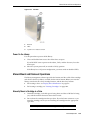
Local Operator Panel
The local operator panel is a touch screen interface built in to the Customer Interface
Module. It enables you to run most of the SLConsole application directly at the library.
LEDs located directly below the local operator panel provide status information:
■
Library Active: Library processor is working.
■
Wait: Library firmware is loading.
■
Service Required: Library is rebooting.
Virtual Keypad
For screen fields that require a text entry, click the keyboard icon to display the virtual
keypad. Invalid characters are grayed out.
Table 2–1
Virtual Keypad Buttons
Button
Function
Insert
If highlighted, inserts text at the cursor position. If not highlighted, replaces text
to the right of the cursor.
Home
Places cursor at the beginning of the field.
Del
Deletes character to the right of the cursor.
End
Places cursor at the end of the field.
Back
Deletes character to the left of the cursor
Clear
Clears the entire field
Left
Moves cursor one character to the left
Right
Moves cursor one character to the right
Log in to the Local Operator Panel
Only one user at a time can log in to the local operator panel.
2-8 StorageTek SL8500 User Guide
Local Operator Panel
1.
If the screen is blank, touch the screen anywhere to activate the Login screen.
2.
Use the virtual keypad to enter your login information.
3.
Click Log on.
Touch Screen Calibration
Alignment of the local operator panel touch screen is calibrated at the factory. If the
touch screen becomes mis-alignment, re-calibrate or reset the touch screen.
■
■
If you have a Linux-based local operator panel, you can re-calibrate it yourself or
reset it to factory setting with the procedures below.
If you have a Windows-based local operator panel, contact your Oracle support
representative.
Re-calibrate the Local Operator Panel
For an accurate calibration, make sure there is no debris on the touch screen.
1.
Log in to the local operator panel.
2.
Select Tools > Calibrate.
3.
Tap Calibrate.
4.
Gently tap in the center of each target with your finger or a pointing stylus.
5.
To save the new settings:
a.
Tap the Click Me buttons within the indicated time period.
If the buttons do not depress, the touch screen is not properly aligned. Discard
the new settings, see Step 6.
b.
6.
Click OK to save the new settings.
To discard the new settings:
a.
Let the timer run out without tapping the Click Me button.
b.
Return to Step 4 and re-calibrate.
The local operator panel reboots automatically after an unsuccessful second
calibration and restores the previously saved alignment.
Reset the Local Operator Panel Calibration
To restore the alignment to the factory settings:
1.
Log in to the local operator panel.
2.
Select Tools > Calibrate.
3.
Click Reset Calibration. The local operator panel reboots.
StorageTek Library Console 2-9
Local Operator Panel
2-10 StorageTek SL8500 User Guide
3
Hardware Activation Files
3
The hardware activation utility enables you to activate and monitor optional features
on the SL8500 library. Some library features are activated by the customer, while others
must be installed and enabled by an Oracle support representative. Features you can
activate include capacity upgrades, dual TCP/IP, redundant electronics, and
partitioning.
■
"Oracle Hardware Activation Files" on page 3-1
■
"Hardware Activation File Installation Overview" on page 3-1
■
"Download a New Hardware Activation File" on page 3-2
■
"Install a New Hardware Activation File on the Target Library" on page 3-2
■
"Delete a Hardware Activation File" on page 3-3
■
"Display Current Hardware Activation Files" on page 3-3
■
"Display the Feature Audit Log" on page 3-3
Oracle Hardware Activation Files
An Oracle hardware activation file is a digitally signed Java archive (.jar) file
containing a feature activation key. You must install one hardware activation file for
each feature purchased. Once installed, the feature is added to the features already
activated on the library.
As of SL8500 firmware FRS_8.31 and SLConsole 6.25, a single partitioning hardware
activation file activates partitioning across an entire library complex.
Legacy Hardware Activation Files
For SL8500 libraries with firmware prior to version FRS_7.00, Oracle support
representatives must install hardware activation files. In addition, all purchased
features are included in a single hardware activation file. When a new hardware
activation file is installed on the library, it replaces older activation files.
After you upgrade a SL8500 library to firmware version FRS_7.00 and above, use the
processes described in this chapter to activate any new features.
Hardware Activation File Installation Overview
1.
Purchase a feature for an Oracle StorageTek library from Oracle.
2.
"Download a New Hardware Activation File" from the Oracle Software Delivery
Cloud and save it to a system accessible to your SLConsole session.
Hardware Activation Files
3-1
Download a New Hardware Activation File
3.
"Install a New Hardware Activation File on the Target Library" using SLConsole.
4.
Configure the new feature. See:
a.
Chapter 4, "Capacity Activation"
b.
Chapter 5, "Library Partitioning"
c.
Chapter 6, "Redundant Electronics".
Download a New Hardware Activation File
1.
Go to the Oracle Software Delivery Cloud at:
http://edelivery.oracle.com/
2.
Click Sign In /Register.
3.
On the Terms & Restrictions screen:
4.
a.
Read the License Agreement and Export Restrictions, and select the check
boxes to indicate your acceptance.
b.
Click Continue.
On the Media Pack Search screen:
a.
In the Select a Product Pack list, select Oracle StorageTek Products.
b.
In the Platform list, select Generic Platform.
c.
Click Go.
5.
Select the SL8500 hardware activation file media pack. Click Continue.
6.
Verify that you have selected the correct media pack. Click Download beside each
desired feature.
7.
Save the file.
8.
Extract the files to a location that you can reach from SLConsole.
Install a New Hardware Activation File on the Target Library
1.
Complete the steps in "Download a New Hardware Activation File" on page 3-2.
2.
Use SLConsole to log in to the target library.
3.
Select Tools > Hardware Activation.
4.
Click the Install Hardware Activation Keys tab.
5.
Enter the full path of the hardware activation file to install, and press Enter.
Optionally, click Browse and navigate to the file location.
6.
Review the hardware activation file details. Click Install.
7.
Click Yes, then OK.
8.
Verify that the activation file has been installed and activated successfully (see
"Display Current Hardware Activation Files" on page 3-3).
Depending on the features activated, you may need to perform additional tasks to
use the new features (refer to the feature-specific chapter).
3-2 StorageTek SL8500 User Guide
Display the Feature Audit Log
Delete a Hardware Activation File
Deleting a hardware activation file is rarely necessary and can impact library
operations. Having extra hardware activation files installed on a library does not
present any problems (for example, capacity activation files that exceed the physical
capacity of the library). The extra activation files are simply not used.
1.
Use the SLConsole to log in to the target library.
2.
Click Tools > Hardware Activation.
3.
Click the Delete Hardware Activation Files tab.
4.
Click the activation file to delete.
5.
Verify the correct activation file is selected, and click Delete....
6.
Click Yes.
Depending on the feature of the hardware activation file, you may need to
perform additional tasks after deleting the file (see "Delete a Partition Definition"
on page 5-4).
Display Current Hardware Activation Files
Use SLConsole to display the features currently activated on a target library.
As of SL8500 firmware FRS_8.31 and SLConsole 6.25, all hardware activation files for a
library complex are shown on a single screen. There is no need to log in to individual
libraries to view hardware activation files for a specific library.
1.
Click Tools > Hardware Activation
2.
Click the Current Hardware Activation Keys tab.
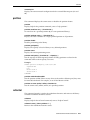
Display the Feature Audit Log
The Feature Audit Log displays a list of all feature activation activity for the life of the
library. Use this log to verify the features installed on the library.
By default, the report is sorted in chronological order. Optionally, you can change the
sort order and rearrange and re-size the columns (see "Modifying the Screen Layout"
on page 2-3 for more information).
1.
Select Tools > Reports.
2.
Expand the Audit Logs folder, and then click Feature Audit Log.
Hardware Activation Files
3-3
Display the Feature Audit Log
3-4 StorageTek SL8500 User Guide
4
Capacity Activation
4
There are two types of capacity:
■
■
Physical capacity — the number of physical storage cells in the library.
Active capacity — the number of storage cells activated with a hardware
activation file. The active capacity does not have to equal the full number of
physical storage cells.
Configuring Active Capacity
The purchased capacity can be activated in a default configuration or a customized
configuration. Coordinate with other library users before configuring the library to
prevent conflicts.
Default Configuration
For a non-partitioned single library with a single host, the SL8500 library controller
can automatically activate the amount of cells you purchased after you reboot the
library. As of FRS_8.31, the default configuration activates capacity from the center and
works to the end until the capacity license is exhausted.
Customized Configuration
For non-partitioned libraries, see "Active Cell Configuration - Single Library" on
page 4-3 and "Active Cell Configuration - Library Complex" on page 4-3.
For partitioned libraries, capacity is automatically applied to the entire partition. The
total number of storage cells allocated to all library partitions cannot exceed the
activated capacity of the library (see "Library Partitioning" on page 5-1).
Guidelines for Customized Activation
■
■
■
Select storage resources in the largest blocks possible (rails, library sides, or library
walls). Avoid selecting individual drives and storage cell arrays.
For best access to drives, activate library inner and outer library walls together and
activate storage cells that are near the tape drives.
When rapid import and export of cartridges is a priority, activate storage cells that
are near the Cartridge Access Ports (CAPs).
Capacity Activation 4-1
Activating Capacity in Non-partitioned Libraries
Activating Capacity in Non-partitioned Libraries
In non-partitioned libraries, be careful in changing the active status of cells because
this may cause orphaned cartridges. A cartridge becomes orphaned when it is
inaccessible to the host. This may occur if you:
■
Change the active capacity status of a non-partitioned library
■
Manually move a cartridge to an inactive or otherwise inaccessible cell
You must resolve orphaned cartridges. SLConsole warns about orphaned cartridges
and provides detailed identifying information. You can then resolve the orphaned
cartridges by performing recovery moves on the listed cartridges (see "Moving
Cartridges (Recovery Moves)" on page 10-3).
Activating Capacity in HLI Hosted Libraries
When a non-partitioned single library or a library in a complex is attached to an HLI
host, the library will temporarily go offline upon reboot and then come back online.
While offline, the library stops accepting new incoming host jobs, but will complete
the jobs already accepted. There is no need to disconnect and re-connect the HLI host.
The library controller sends an asynchronous message to any host, notifying them that
the library configuration has changed. ACSLS hosts must perform an audit of an
non-partitioned library to account for the new capacity. Hosts can continue processing
jobs while the audit takes place.
SLConsole Capacity Icons
Table 4–1
Single Library Capacity Icons
Icon
Description
(white rectangle)
Inactive — cell not yet licensed for use
(white rectangle with triangle) Active — cell licensed for use
(purple rectangle)
Selected — cell designated for activation or deactivation
(dark red rectangle)
No Activation Needed — resource is active by default
Table 4–2
Library Complex Capacity Icons
Icon
Description
(white rectangle)
(red rectangle)
Inactive — cell not yet licensed for use
Active — cell licensed for use.
Selected — cell designated for activation or deactivation
(black border)
Capacity Activation using SLConsole
Capacity changes cannot be performed at the local operator panel.
No changes are committed to the library controller database unless you click Apply at
the top of the screen and confirm your choice. If you log off the SLConsole session, if
4-2 StorageTek SL8500 User Guide
Capacity Activation using SLConsole
the session times out, or if the connection to the library is lost before you save changes,
any changes will be lost. At any time, you can discard changes and restore the last
saved configuration by clicking Refresh.
Capacity is automatically applied in a partitioned library. You
may only apply capacity to a non-partitioned library.
Note:
Active Cell Configuration - Single Library
For a single library you can design the active cells configuration or display an active
cells report.
Design the Active Cells Configuration
You can either accept the default configuration or choose your own.
1.
Select Tools > Select Active Cells.
2.
Click the Design By Library tab.
3.
To activate the default configuration and remove drives from the media validation
pool, click Reset Capacity. Go to Step 6.
To configure a custom capacity design, go to Step 4.
4.
To customize the capacity design, choose areas of the library from the menus and
click Add or Remove.
5.
When you have completed the configuration, click Apply User Design.
6.
Click Yes. If there are no warnings, click OK. Continue to Step 8.
7.
If there are warnings, click Details >>
If orphaned cartridges are reported, do not continue with this process until you
have performed recovery moves on the listed cartridges (see "Moving Cartridges
(Recovery Moves)" on page 10-3).
8.
Reconfigure library host applications to recognize the changes (see the tape
management software documentation).
Display Active Cells Report
These reports only display data saved to the library controller database.
1.
Select Tools > Select Active Cells, then select the View Reports tab.
2.
Select a report:
■
■
3.
Cartridge and Cell Media Summary - displays cell addresses and volume
serial numbers (volsers) for the media in each partition
Orphaned Cartridge Report - displays a detailed list of all orphaned
cartridges
To save a report to a comma-separated value (csv) file, click Save to File.
Active Cell Configuration - Library Complex
You can either accept the default configuration or to choose your own.
Capacity Activation 4-3
Capacity Activation using SLConsole
Design the Active Cells Configuration
1.
Select Tools > Active Cells.
2.
To apply a default capacity configuration and remove drives from the media
validation pool, click Reset Capacity. Go to Step 5.
To configure a custom capacity design, go to Step 3.
3.
To customize capacity, click the areas of the library to remove or add:
■
Rail x, Right or Rail x, Left buttons to highlight the right or left rails
■
Outside Wall to highlight the outside wall of the rail
■
Inside Wall to highlight the inside wall of the rail
■
Full Library to highlight the full library
4.
When you have completed the configuration, click Apply User Design.
5.
Click Yes. If there are no warnings, click OK. Continue to Step 7.
6.
If there are warnings, click Details >>
If orphaned cartridges are reported, do not continue with this process until you
have performed recovery moves on the listed cartridges (see "Moving Cartridges
(Recovery Moves)" on page 10-3).
7.
Reconfigure library host applications to recognize the changes (see the tape
management software documentation).
4-4 StorageTek SL8500 User Guide
5
Library Partitioning
5
Library partitioning reserves library resources (drives and cells) for the exclusive use
of specified hosts, and is an optional feature enabled with a hardware activation file
(see "Hardware Activation Files" on page 3-1).
Partitions support non-contiguous resource assignments. However, CAPs are a shared
library resource and are not assigned to specific partitions. You can partition a single
library or a library complex using SLConsole.
Single Library Partitioning
■
Up to eight partitions.
■
Smallest slot increment is one array.
■
Smallest drive increment is one drive.
■
Requires minimum SL8500 firmware 7.01 and SLConsole 5.50.
Library Complex Partitioning
Up to 16 partitions total, with a maximum of eight per library.
■
■
Smallest slot increment is a quarter rail.
■
Smallest drive increment is one drive.
■
Partition boundaries can span across pass-thru ports (PTPs).
■
Requires minimum SL8500 firmware 8.31 and SLConsole 6.25.
■
Requires the following minimum level for library management software:
–
ACSLS 8.3, HSC 6.2: PTF L1H16SG (VM), ELS 7.0: PTF L1H15SI (MVS), ELS
7.1: PTF L1H16SJ, ELS 7.2: integrated
Activated Capacity and Partitions
As you allocate cells to a partition, the library controller automatically activates these
cells. The number of cells allocated to each partition is subtracted from the total
purchased capacity authorized in the hardware activation files. The total cells allocated
to partitions never exceeds the purchased capacity of the library. Therefore, ensure
there is enough purchased active capacity for the partitioning design.
For more information about hardware activation files, see Chapter 3, "Hardware
Activation Files".
Library Partitioning 5-1
Hosts and Partitions
Hosts and Partitions
A host that has access to a partition is granted use of all available storage cells,
cartridges, and drives in that partition. The host has no access to resources that are
assigned to other partitions in the library.
Individual ACSLS hosts can control one or more SL8500 library partitions. Individual
HSC hosts and groups of up to 16 HSC hosts that share a Common Control Dataset
(CDS) can control a single partition.
Resource allocation guidelines:
■
■
■
■
Select storage resources in the largest blocks possible (rails, library sides, or library
walls). Select complete library rails to minimize the use of elevators. In a library
complex, keep a partition contained within a library to minimize the use of PTPs.
For best access to drives, activate library inner and outer library walls together.
Avoid selecting individual drives and storage cell arrays. Individually select and
deselect resources only when you need to fine-tune a capacity that has already
been broadly defined in larger blocks.
For quicker import/export of cartridges, partition storage cells close to the CAPs.
For quicker access to stored data, partition storage cells close to the tape drives.
Shared Resources - CAPs
In a partitioned library, hosts share CAPs. Each host reserves the CAP for exclusive use
as needed, then releases the CAP when it is no longer required. A host can reserve a
CAP if the CAP is empty, closed, locked, and not already reserved by another
partition. CAP auto enter mode is disabled in partitioned libraries, because it interferes
with the reservation system. See "Auto Enter Mode" on page 8-1.
Once the enter/eject operation is complete, the host releases the reservation and makes
the CAP available to other host partitions. Then, either the user terminates the HSC or
ACSLS enter command or the host automatically terminates the command. The library
releases the CAP after verifying that the CAP is closed and empty.
If for any reason a CAP reservation is not released and the enter or eject command
cannot be terminated in ACSLS or HSC on the host, a library administrator must
override the host partition reservation (see "CAP Operation - Override a CAP
Reservation" on page 5-6 for details).
Planning and Preparations
You should verify minimum firmware and SLConsole requirements for partitioning.
Then, configuring and administering ACSLS and HSC host software applications.
Before creating a partition, verify the physical configuration and resolve and orphaned
cartridges.
Verifying the Physical Configuration of a Partition
Before creating partitions, verify that all tape drives and cartridges have been moved
to the proper location. For example, if a partition will be owned by an ACSLS host,
only ACSLS-compatible drives can be installed in that partition, and all cartridges
containing data for the ACSLS host must be migrated to the partition.
5-2 StorageTek SL8500 User Guide
Library Partitioning
Resolving Orphaned Cartridges
An orphaned cartridge is a cartridge which is inaccessible to a host. Orphaned
cartridges can occur when you change the capacity of a partition, delete a partition, or
move a cartridge to a cell or drive that is not allocated to a partition.
In a partitioned library, orphaned cartridges can cause data loss. A host that finds an
orphaned cartridge in its partition may treat the cartridge as a scratch volume and
overwrite the data.
SLConsole will warn you when it identifies orphaned cartridges. Resolve the
orphaned cartridges by performing recovery moves on listed cartridges. Recovery
moves transfer the orphaned cartridges to accessible locations within their parent
partitions. See "Moving Cartridges (Recovery Moves)" on page 10-3.
Maximizing Library Performance
Identifying workloads can improve library performance. Generally, a workload is
defined as a group of tape drives and cartridges used for a particular application. To
maximize the performance of the SL8500 library:
■
■
■
■
Minimize elevator operations between rails within a library and pass-thru
operations between libraries. Limit the distance cartridges must travel.
Minimize contention for library resources between different application requests.
Configure the library so each workload uses a separate pool of library resources
(tape drives, data tapes, scratch tapes, and free cells). Group workload resources as
close together to minimize PTP and elevator activity.
Place applications that require significant enters and ejects on rails adjacent to
CAP magazines. Inactive tapes should be placed on the top rail. These tapes are
not entered or ejected frequently, and the top rail is not directly adjacent to a CAP
magazine.
■
Put different types of tape drives on different rails to reduce pass-thru activity.
■
Ensure there are enough tape drives and storage cells to support a workload.
Library Partitioning
■
"Instructions Tab - Prepare for Partitioning" on page 5-3
■
"Summary Tab - Add or Delete Partition Definitions" on page 5-4
■
"Design Tab - Allocate and Verify Resources in Partitions" on page 5-5
■
"Commit Tab - Commit Partitioning Changes" on page 5-6
■
"Reports Tab - Single Library Only - Generate Partitioning Reports" on page 5-6
No actual changes to partitioning occur until the design is
applied using the Commit (Step 4) tab.
Note:
Instructions Tab - Prepare for Partitioning
1.
Quiesce any host operations.
Host applications such as library management software (ACSLS, ELS) and data
management software (backup and archiving applications) should not try to use
the library during partitioning.
Library Partitioning 5-3
Library Partitioning
2.
Select Tools > Partitions.
3.
Review the Instructions (Step 1) tab.
Summary Tab - Add or Delete Partition Definitions
Use this procedure to add or delete partition definitions.
Add a Partition Definition
1.
Select the Summary (Step 2) tab of the partitions interface.
2.
On the left side of the screen, note:
■
Total Library Resources (storage cells, drive bays, CAPs and CAP cells and
activated capacity)
■
Resources Allocated (assigned to a partition)
■
Resources Unallocated (not assigned to a partition)
If the library has not previously been partitioned, no resources will be allocated
and the full capacity will be unallocated.
3.
In the Partition Allocation Summary area, click Add Partition.
4.
Select a partition ID from the menu. Partitions do not have be selected
consecutively. Optionally, enter a partition name.
5.
Click OK.
6.
Repeat steps 3-5 until you have added all required partitions.
Delete a Partition Definition
When you delete a partition:
■
All resources allocated to the partition are marked available.
■
All host connections for the partition are deleted.
■
The partition ID is deleted.
Use this procedure to delete a partition from the library.
1.
To prevent orphaned cartridges, move valid data cartridges out of the partition
that will be deleted.
2.
Select the Summary (Step 2) tab of the Partitions interface.
3.
In the Partition Allocation Summary area, select the table row of the partition to
delete.
4.
Click Delete Partition.
5.
Make sure the partition number is correct. Click OK.
6.
For a library complex, proceed to step 7. For a single library, click the Design by
Library (Step 3) tab. Then, click Verify.
7.
If there are warnings, click Details >>
If orphaned cartridges were found, perform recovery moves on all listed volumes.
See "Moving Cartridges (Recovery Moves)" on page 10-3. After you have resolved
all orphaned cartridges, re-verify the partitioning configuration.
8.
If there are no warnings, commit the partition design. See "Commit Tab - Commit
Partitioning Changes" on page 5-6.
5-4 StorageTek SL8500 User Guide
Library Partitioning
Design Tab - Allocate and Verify Resources in Partitions
Single Library
Use this procedure to allocate and verify library resources to partitions in a single
library. For a library complex, see "Library Complex" on page 5-5.
1.
Select the Design by Library (Step 3) tab of the Partitions interface.
2.
Use the list control to select a partition ID.
3.
Select the sections of the library to add to the partition using the menus:
■
All Rails, Rail 1, Rail 2, Rail 3, or Rail 4 — defines the rail of the selection
■
Left/Right Sides, Left Side, or Right Side — defines the side of the selection
■
Inside/Outside Walls, Inside Wall, or Outside Wall — defines the wall of the
selection
4.
Click Add to allocate the specified resources to the partition. Click Remove to
un-allocate the resources from the partition.
5.
To refine the partition, select Remove Array or Add Array from the rails menu.
Then, click on drive(s) and array(s) to add/remove them from the partition.
6.
Repeat steps 2 - 5 for each partition ID.
7.
When you complete the partition design, click Verify.
8.
If there are warnings, click Details>>
If orphaned cartridges were found, perform recovery moves on all listed volumes.
See "Moving Cartridges (Recovery Moves)" on page 10-3. After you have resolved
all orphaned cartridges, re-verify the partitioning configuration.
9.
If there are no warnings, see "Commit Tab - Commit Partitioning Changes" on
page 5-6.
Library Complex
Use this procedure to allocate resources to partitions in a library complex. For a single
library, see "Single Library" on page 5-5.
1.
Select the Design (Step 3) tab of the Partitions interface.
2.
Select the radio button of the partition.
3.
Select the resources of the library to include in the partition.
■
Rail 1 Left, Rail 1 Right, Rail 2 Left, and so on — selects half a rail.
■
Full Library — selects the entire library
■
Outside Wall or Inside Wall — selects a quarter rail
To un-highlight areas, select any of the above again.
4.
Click Add to allocate the selected resources to the partition. Click Delete to
remove the selected resources from the partition.
5.
Repeat steps 2-5 for each partition.
6.
Commit the partition design. See "Commit Tab - Commit Partitioning Changes" on
page 5-6.
Library Partitioning 5-5
CAP Operation - Override a CAP Reservation
Commit Tab - Commit Partitioning Changes
Use this procedure to apply the partition configuration. No changes are made to the
library until you complete these procedures.
1.
When all partitions are configured, select the Commit (Step 4) tab.
2.
Click Apply.
3.
If there are no warnings, click OK. If there are warnings, click Details >>.
If orphaned cartridges were found, perform recovery moves on all listed volumes
before committing partitioning changes. See "Moving Cartridges (Recovery
Moves)" on page 10-3.
Reports Tab - Single Library Only - Generate Partitioning Reports
1.
Select the Reports tab of the Partitioning interface.
2.
Select a type of report from the menu:
■
■
Cartridge Cell and Media Summary — displays cell addresses and volume
serial numbers (volsers) for the media in each partition
Orphaned Cartridge Report — displays cell addresses and volume serial
numbers (volsers) for orphaned cartridges
■
Partition Summary — displays the resources allocated to each partition
■
Partition Details — displays details for a specific partition ID
3.
Click Print to print a hard copy.
4.
Click Save To File to create a comma-separated value (csv) file.
CAP Operation - Override a CAP Reservation
If for any reason a CAP reservation by a partition is not released and the enter or eject
command cannot be terminated in ACSLS or HSC on the host, use this procedure to
override an existing CAP reservation.
You must follow all steps in this procedure, or the CAP could
be left unavailable to all partitions.
Note:
1.
Select Tools > Diagnostics.
2.
Expand the CAP folder. Click the reserved CAP to override.
3.
Click the Unreserve tab. Note the partition ID for the CAP.
4.
Click Apply to override the reservation.
5.
Select OK. The CAP user changes to "default", which makes the CAP unavailable
to all partitions.
6.
If the CAP is locked, unlock it. See "Lock/Unlock a CAP" on page 8-3.
7.
Open the CAP. Remove any cartridges and label them with the partition ID.
8.
Close the CAP. The library verifies the CAP is empty. The CAP status changes to
"unreserved", which makes the CAP available to all partitions.
9.
Determine if the cartridges should be re-entered into the library and enter the
cartridges into the correct partition.
5-6 StorageTek SL8500 User Guide
6
Redundant Electronics
6
The optional redundant electronics (RE) feature provides failover protection for the
library controller. This allows an Oracle support representative to replace a faulty card
while the library is online and provides minimal disruption to library operations
during firmware upgrades.
Note:
Any reference to the HBC card also refers to the HBCR card.
Requirements
■
Two library controller (HBC) cards
■
Two drive controller (HBT) cards
■
Minimum SL8500 firmware version FRS_6.00 and SLConsole version 4.65
■
Hardware activation file (see Chapter 3, "Hardware Activation Files")
Redundant Electronics Overview
If the library controller or drive controller experiences errors, operations can switch to
the standby controller, with minimal disruption to library and host operations. The
library controller and drive controller installed on the same side of the card cage are
always switched as a pair. Failover can be initiated automatically or manually. A
failover cannot occur if:
■
The standby library or drive controller is in a fault or eject state.
■
The standby code is not running on the standby library or drive controller cards.
■
A firmware download or card initialization is in progress.
In a failover, the active library controller attempts to complete all in-process jobs and
copies the cartridge database to the standby controller card. If the database cannot be
copied (usually only in a sudden failure), you must perform an audit after failover
completes (see "Audits" on page 7-8). Any in-transit cartridges are returned to their
home slots. If a cartridge cannot be moved to its home slot, it is moved to a library
system cell. The host must return the cartridge to its home cell (see the ACSLS and ELS
documentation).
After all in-process jobs have completed or timed out, the card roles are switched.
Active software is brought up on the standby controller. This controller becomes active
and the previously active controller becomes the standby. If the standby software
cannot be brought up on the previously active controller, the controller enters a fault
state.
Redundant Electronics
6-1
Redundant Electronics Overview
Automatic Failover
An automatic failover can be initiated by either the active or standby library controller.
The active library controller initiates an automatic failover when:
■
Its partner drive controller card is not installed or it is not communicating.
■
It detects a catastrophic internal software error.
The standby library controller initiates an automatic failover if the active controller is
not functioning normally.
Manual Failover
Before initiating a manual switch, you should verify that the standby library and drive
controllers are running normally. You can initiate a manual switch using:
■
■
■
Host tape management (ACSLS or ELS): Failover can be initiated from either the
active or standby library controller. The standby library controller accepts only set
host path group and force switchover HLI requests.
SLConsole: Failover is initiated from the active library controller only (see
"Manual Redundant Electronics Switch" on page 6-4).
CLI: Failover can be initiated from either the active or standby library controller.
This function is available to your Oracle support representative only.
You may want to perform a manual switch after initial installation of the standby
cards, after a firmware upgrade, or periodically to check the failover function is
working properly. It is not possible to manually switch the library controllers without
the drive controllers — the controllers are always switched as a pair.
Connections
Each library controller card requires a unique IP address. For libraries with Dual
TCP/IP, each card requires two unique IP addresses: one for the primary port (2B) and
one for the secondary (2A) port. A library equipped with both RE and Dual TCP/IP
requires four unique IP addresses.
The failover process is minimally disruptive to host operations.
■
■
■
Users of tape management software (Symantec or Virtual Storage Manager) do not
see an interruption.
HLI host applications (ACSLS and ELS) queue requests during the failover process
for completion after the failover switch. For ACSLS, only mount and dismount
requests are affected (see the ACSLS and ELS documentation).
SLConsole and CLI connections are terminated. You must re-establish connections
to the library using the IP address or DNS alias of the new active library controller
(the former standby controller).
Firmware Upgrades
Firmware upgrades for libraries with RE are minimally disruptive to library
operations. New code is loaded and unpacked simultaneously on the active and
standby controller cards and on all devices. The code is then activated, and the active
and standby controllers and most devices are re-initialized. Under most circumstances,
robot initialization is bypassed.
6-2 StorageTek SL8500 User Guide
Display Redundant Electronics Information
The loading, unpacking, and activation of code are not disruptive to library operations
until the library is rebooted. During the reboot process (which takes approximately 10
minutes), the HLI host applications (ACSLS and ELS) queue all mount and dismount
requests. After the reboot is complete, the queued requests are submitted to the library
controller.
See "Upgrade Library Firmware" on page 7-2 for firmware download and activation
information.
Controller Card Status
Controller card status is indicated by LEDs on the card and displayed in SLConsole.
LEDs
The LEDs and meanings are the same on both card types (HBC and HBT).
Table 6–1
LED Status Indicators
LED
Definition
ACTIVE - Green
Card is functioning as the active and is running active code.
STANDBY - Amber
Card is functioning as the standby and is running standby code.
FAULT - Red
Card has experienced a serious error.
EJECT OK - Blue
Support representative can safely initiate a card eject.
SLConsole Status
Some SLConsole screens identify the individual library controller with an A or B
suffix. A indicates the left card slot and B indicates the right card slot, as viewed from
the back of the library. To display the status the controller cards in SLConsole, see
"Display Redundant Electronics Information" on page 6-3.
Table 6–2
SLConsole Controller Card Statuses
Status
Definition
Duplex: Software ready,
switch possible
Active library controller is functioning normally.
Not installed
Card is not installed in the library.
Ok
Active or standby drive controller card is functioning normally.
Pre-standby:
Standby library controller card is loading standby code and is not
ready to be used in an automatic failover or manual switch.
Software not ready
Standby:
Software ready
Standby library controller card is functioning normally and can be
used for an automatic failover or manual switch.
Display Redundant Electronics Information
1.
Select Tools > System Detail.
2.
Click the Redundant Electronics folder to display summary information.
3.
For detailed information about each card, expand the Redundant Electronics
folder in the navigation tree.
4.
Select a card (see "SLConsole Status" on page 6-3 for status meanings):
Redundant Electronics
6-3
Manual Redundant Electronics Switch
a.
hbca: Library controller, A (left) slot
b.
hbcb: Library controller, B (right) slot
c.
hbta: Drive controller, A (left) slot
d.
hbtb: Drive controller, B (right) slot
Manual Redundant Electronics Switch
This procedure is not available at the local operator panel.
1.
Verify the device state of the card indicates "switch is possible" (see "Display
Redundant Electronics Information" on page 6-3).
2.
Select Tools > Diagnostics.
3.
Select the Redundant Electronics folder
4.
Click Apply to begin the switch process. If there is a problem with the standby
library and drive controller cards, you are not allowed to continue with the switch.
5.
If there are no errors, click Yes.
6.
Click OK to log off the SLConsole.
7.
Wait until the switch is complete before logging back into the library. You must
specify the IP address or DNS alias of the new active controller to log in.
6-4 StorageTek SL8500 User Guide
7
Library Management
7
■
"Library and Device Status Overview" on page 7-1
■
"Upgrade Library Firmware" on page 7-2
■
"Display Library Information" on page 7-3
■
"Generate Library Diagnostic Files" on page 7-5
■
"Clear Library Status Alerts" on page 7-6
■
"Perform a Library Self-Test" on page 7-6
■
"Reboot the Library" on page 7-7
■
"Place the Library Online or Offline" on page 7-7
■
"Audits" on page 7-8
Library and Device Status Overview
SLConsole shows health status for devices, SLConsole communication, and the library.
Table 7–1
Icon
Status Indicators
Meaning
Normal
Warning
Error
Health Status of a Device
Found in navigation tree of System Details and Diagnostics page.
■
Normal — library device is functioning normally
■
Warning — device is offline or operating in a degraded state
■
Error — device has experienced a failure
Communication Status
Found in lower left of all SLConsole screens. Indicates the communication status
between SLConsole and the library controller.
■
Normal — SLConsole is communicating normally with the library controller
Library Management
7-1
Upgrade Library Firmware
■
Warning — server is taking longer than 10 seconds to respond
■
Error — server is taking longer than 30 seconds respond
After about 30–60 seconds of lost communication with the library controller, the
heartbeat monitor turns gray, then red, and displays:
Heartbeat message not received from the library controller.
Log off the SLConsole and log on again to restore communication.
Health Status of the Library
Found in lower right of all SLConsole screens.
■
Normal — all library devices are functioning normally
■
Warning — one or more library devices is offline or operating in a degraded state
■
Error — one or more library devices has experienced a failure
After a device error is fixed, the library health indicator changes to "Warning". The
indicator will not change to "Normal" until the library is taken offline. If there are
multiple problems with a device or status alert condition, the health indicator
displays the most severe condition.
Upgrade Library Firmware
To upgrade firmware, use the SLConsole code load utility. You cannot perform a code
download or activation at the local operator panel.
Library firmware does not contain drive code upgrades (see drive-specific
documentation). Firmware upgrades for libraries with the redundant electronics
feature are minimally disruptive (see Chapter 6, "Redundant Electronics").
Download Code to the Library Controller
1.
Locate the firmware upgrade package (.jar file) at: http://edelivery.oracle.com
2.
Download the code to your workstation.
3.
Log in to the SLConsole.
If you are upgrading an SL8500 complex, you can connect to any library in the
complex. The upgrade downloads simultaneously to all libraries in the complex
from the single SLConsole session.
4.
Select Tools > Diagnostics, and then click the Library folder.
5.
Click the Load Code tab.
6.
Enter the full path of the firmware package to download, and then press Enter.
Optionally, click Browse and navigate to the file location.
7.
Verify the contents and file name. Click Load.
8.
Click OK. The download process could take up to 10 minutes.
Next to the Failed label, you should see "0". If there are any
failures indicated, contact your Oracle support representative for
assistance.
Note:
7-2 StorageTek SL8500 User Guide
Display Library Information
9.
After the code unpacks, activate the code at any time (see "Activate Code on the
Library Controller" on page 7-3).
Activate Code on the Library Controller
The library controller can store up to two versions of firmware, but only one is active.
The active version is identified as "running". You can restore the earlier firmware
version if required.
A reboot of the library or entire library complex is required. Schedule the code
activation accordingly.
1.
If you have not done so, download and unpack the code (see "Download Code to
the Library Controller" on page 7-2).
2.
Select Tools > Diagnostics, and then click the Library folder.
3.
Click the Activate Code tab.
4.
In the Target list, select the code package to activate (in this case SL8500 Code).
5.
In the Available Versions section, select the code version to activate.
6.
Click Activate.
7.
Click OK to start activation.
Caution: POTENTIAL INTERNAL FILE CORRUPTION. Do not
reboot any devices in the library or execute any operations on the
library while activating code.
8.
When the activation process finishes, click OK to reboot the library.
9.
Click OK to terminate the SLConsole session.
10. After library initialization completes, log in to SLConsole.
Display Library Information
■
"Display Library Status" on page 7-3
■
"Display Library Properties" on page 7-4
■
"Library Reports" on page 7-4
■
"Display Library Power Supply Information" on page 7-5
Display Library Status
1.
Select Tools > System Detail, and then click the Library folder in the navigation
tree.
2.
Click the Status tab.
3.
Select a secondary tab:
■
■
General - displays the current operational state of the library. These values
update whenever there is host activity, background operations, or operator
activity.
Complex - displays the current operational state of a library complex.
Library Management
7-3
Display Library Information
■
■
■
Status Module - displays library status alerts. This feature is available only if
service is active on the library. If service is not active on the library, this screen
will be blank except for a message indicating that the "Service activation is not
valid". If you see the "warning" status, a failure may occur. Contact a service
representative.
HLI - displays the current status of all HLI interface ports on the library.
Information includes the local TCP/IP socket, local IP, connection status, port
status, and transmission sent and received from the time of connection.
Internal Networks - displays port status
Display Library Properties
1.
Select Tools > System Detail, and then click the Library folder.
2.
Click the Properties tab.
3.
Select a secondary tab:
■
■
■
■
General - displays the physical, mechanical, logical, and network
configuration of the library. Some of the information can be set up
automatically during library initialization, while other information can be
defined by the user.
Complex - displays IP address information for a library complex.
Library Controller - displays details of the library controller, including the
serial number and firmware versions.
Drive Controller - displays details of the drive controller, including the serial
number and current firmware versions.
Library Reports
Use this procedure to display, search, or save library reports available from the Tools >
Reports menu. Additional reports are available from the Tools > Partitions menu.
All report output is a static display of information at the time the report is generated.
Click Update in the upper right corner to refresh the information.
1.
Select Tools > Reports.
2.
In the navigation tree, expand a report category.
3.
Select a report.
Search a Library Report
1.
With the report displayed, click Search.
2.
Enter a text string (case-sensitive and wildcards are invalid). Click Search.
Save Library Report Data to a File
1.
With the report displayed, click Save.
2.
Browse to the desired directory, enter a file name, select a format, and click Save.
Display Library Events Statistics
The General Events Statistics Report displays summary statistics for library
operations. For each event, the report lists the event type, number of occurrences, and
the date and time of the most recent occurrence of the event.
7-4 StorageTek SL8500 User Guide
Generate Library Diagnostic Files
To change the sort order of the screen or rearrange and resize the columns, see
"Modifying the Screen Layout" on page 2-3.
1.
Select Tools > Reports.
2.
Expand the Statistics folder, and then click General Events.
Display Library Power Supply Information
For power configuration information, see the SL8500 Systems Assurance Guide "Power"
chapter found on OTN.
The Power Supply Data screen displays summary information for all power supplies
in the library. Use this screen to monitor the status of the power supplies for
maintenance or replacement. By default, the display is sorted by internal address. To
change the sort order, and rearrange and resize the columns, see "Modifying the Screen
Layout" on page 2-3.
1.
Select Tools > System Detail.
2.
In the Library navigation tree, click the Power Supply folder to display summary
information.
3.
For detailed information, expand the Power Supply folder. Select a power supply.
Generate Library Diagnostic Files
These procedures generate files to diagnose library problems.
Transfer the Library MIB File
Use this procedure to transfer the public SNMP management information base (MIB)
file to an Oracle support representative.
1.
Select Tools > Diagnostics.
2.
Click the Library folder in the navigation tree.
3.
Click the TransferFile tab.
4.
Select the Transfer Type of SNMP MIB. Click Transfer File.
5.
Browse to the desired directory, and then enter the file name with a .txt suffix.
6.
Click Save.
7.
E-mail the file to your Oracle support representative.
Generate and Transfer the Library Log Snapshot File
If a support representative requests a library Log Snapshot, use this procedure to
generate and transfer the file. The system saves the file in an encrypted format, so you
cannot view or edit it. You must save the log within 15 minutes of generation.
1.
Select Tools > Diagnostics.
2.
Click the Library folder in the navigation tree.
3.
Click the Transfer File tab.
4.
Select the Log Snapshot radio button.
5.
In the Selected Devices list, select either All Devices or Selected Device. If you
choose Selected Device, select the device.
Library Management
7-5
Clear Library Status Alerts
6.
Click Generate Log Snapshot on Library.
7.
Click Yes, and then OK.
8.
Click Transfer Log Snapshot To Your Computer.
9.
Browse to the desired directory or enter the directory path. Click Save. The file is
named automatically.
10. E-mail the file to your Oracle support representative.
Clear Library Status Alerts
You can only clear alerts marked as "Clearable" and only if service is active on the
library.
Clearing an alert only removes it from the Status Module display; it does not resolve
the underlying cause. The library health indicator returns to "Normal" if there are no
other device or status alerts. If the alert is subject to periodic updates, it will reappear
at the next update cycle.
1.
Select Tools > System Detail, and click the Library folder.
2.
Click the Status tab, and then the Status Module tab.
3.
On the Clear Alert Number list, select the alert number to clear, and then click
Apply.
Perform a Library Self-Test
The self-test diagnostic can help diagnose library operational problems. A self-test
typically runs after the library is installed. You can run library self-test routines in
either non-disruptive (cartridges are returned to home cells) or disruptive mode
(cartridges may be moved to new cells).
When performing a self-test, the system:
■
■
■
■
Checks the communication path between the library controller, drives, elevators,
and robots.
Performs get and put operations to check the health of the robots, elevators, and
CAPs. This includes get and put operations from a reserved system cell to a
random empty storage cell or CAP cell.
Performs a full library audit.
Performs mounts and dismounts of diagnostic cartridges for all the drives
installed in the library. The self-test does not begin unless a diagnostic cartridge is
found in the system cells. If the system finds a compatible diagnostic cartridge, the
self-test repeats for each drive type. If the system does not find a diagnostic
cartridge for a drive type, the system skips the mount/dismount operation for the
drive.
Note: Before performing a disruptive test, the library must be taken
offline. See "Place the Library Online or Offline" on page 7-7.
1.
Make sure the proper drive diagnostic cartridges are in the library (see "Display
Cartridge Information" on page 10-2).
2.
Select Tools > Diagnostics, and click the Library folder.
7-6 StorageTek SL8500 User Guide
Place the Library Online or Offline
3.
Click the SelfTest tab.
4.
In the Mode list, select the type of self-test:
■
■
Non-Disruptive - all cartridges used in the test are returned to their original
locations
Disruptive - the library must be taken offline to all hosts before running this
test
5.
Click Run. When the test completes, the results of the test display.
6.
For disruptive tests, bring the library online to resume normal operations.
Reboot the Library
Use this procedure to reboot the library. This process involves reloading the firmware
from flash memory and restarting the library controller.
1.
Select Tools > Diagnostics.
2.
Click the Library folder in the navigation tree.
3.
Click Reboot.
4.
All other users must log off. Click OK.
5.
If the library is online, click OK to take the library offline.
6.
Click OK to reboot the library.
7.
Click OK to terminate this SLConsole session. Do not log back in to the SLConsole
until the library has fully initialized.
Place the Library Online or Offline
Use this procedure only if you are not using ACSLS or ELS tape management
software, or if ACSLS/ELS servers cannot communicate with the library. For
instructions on changing the state of the library and its components through ACSLS or
ELS, see the appropriate tape management software documentation.
Place the Library Offline
You may need to place the library offline at the following times:
■
Before powering down the library
■
Before opening a library access door
■
When the library is inoperative and requires maintenance
To place the library offline:
1.
Take all library drives offline. See "Change a Drive Online/Offline Status" on
page 9-4.
2.
Select Tools > System Detail.
3.
Click the Library folder in the navigation tree.
4.
Click the Status tab, and then the General tab.
5.
In the Transition Request field, click Take offline.
6.
Click Apply. Before the library goes offline, all outstanding library jobs complete.
Library Management
7-7
Audits
7.
Wait for the offline confirmation message. If the library does not come offline,
check the status of the library.
Bring the Library Online
1.
Select Tools > System Detail.
2.
Click the Library folder in the navigation tree.
3.
Click the Status tab, and then the General tab.
4.
In the Transition Request field, click Bring online.
5.
Click Apply.
6.
If applicable, bring the library online to ACSLS and ELS hosts. See the ACSLS and
ELS documentation.
Bring the Drives Online
LTO drives are automatically brought online when you bring the library online. To
bring T-series drives online manually:
1.
To verify that the T-series drives are ready and online, press the MENU switch.
The display should now read Online.
2.
If the drive displays Offline, press the SELECT switch once to bring it online.
■
■
■
If the drive message indicates Online, the transition to online completed.
If the Onl Pend message appears, the online state is pending due to
completion of diagnostic tests.
If other messages appear, refer to the drive documentation.
Audits
An audit is the process of cataloging or verifying cartridge locations within a library
and updating the cartridge database. The database contains the volume ID (vol-id or
volser), current location (in library internal address format), and verified status (true
or false).
You can use the SLConsole to perform a "Physical Audit", "Verified Audit", or virtual
audit. A virtual audit displays a report listing the contents of the cartridge database.
Audit times vary according to the type of audit, size of the library, the number of
HandBots, and the speed of the scan engine for the barcode scanner.
The library performs an audit when:
■
One or both access doors have been opened and closed.
■
An audit request is made through the SLConsole.
■
■
A host request to audit the library is entered. (System-level problems may occur if
a host’s record of the cartridge does not match what is in the cartridge database of
the library controller.)
The library initializes at power on.
Audit Indicator
To indicate an audit is in progress, the SLConsole displays a spinning indicator and the
message "Audit in progress". When you see this indicator do not open the library
access door. This will cause the audit to restart.
7-8 StorageTek SL8500 User Guide
Audits
The audit indicator only displays when an audit is initiated automatically (library
access door has been opened and closed, library power up or reboot). The indicator
does not display for audits initiated from SLConsole or the host.
Physical Audit
In a physical audit, the robot visits cartridge locations and records the vol-id of the
cartridges. The library controller updates the cartridge database based on the physical
audit. This audit changes the “verified” status of the cartridge locations to true.
You can manually initiate a physical audit for either the entire library or a specific
range of cells.
Note:
You cannot stop a physical audit after it begins.
Audit the Entire Library
The robot verifies all cells (storage, CAP, drive, reserved). Although an entire library
audit is a background process and does not interrupt library operations, it does require
sharing of robot resources. It is not recommended that you run this audit during peak
activity periods.The audit takes approximately 1/2 second per cartridge slot.
After a few hours of the audit, you can view the Cartridge Summary report for the
latest cartridge locations and vol-ids. See "Library Reports" on page 7-4.
1.
Select Tools > Diagnostics.
2.
Click the Library folder on the navigation tree.
3.
Click the Audit tab.
4.
a.
In the Entire Library section, click Yes.
b.
Click Audit.
Click OK to begin the audit.
Audit a Range of Cells
During this audit, the library verifies only a specific range of storage cells (including
the CAP and drives). The audit information is displayed on the SLConsole while the
audit is performed. After the audit completes, view the Cartridge Summary report for
the latest cartridge locations and vol-ids. See "Library Reports" on page 7-4.
1.
Select Tools > Diagnostics.
2.
Click the Library folder on the navigation tree.
3.
Click the Audit tab.
a.
In the Entire Library section, click No.
In the Physical Audit section, select Yes.
In the Verified Audit section, select No.
4.
b.
In the Start Address and End Address sections, select the device types to audit
and the internal address locations.
c.
Click Audit.
Click OK to begin the audit. The Audit Console section displays the progress of
the audit.
Library Management
7-9
Audits
Verified Audit
A verified audit validates the status of a specific cartridge location or range of
locations (including CAPs and drives) in the cartridge database. If a cartridge address
has a verified status of false, a physical audit of that location is performed and the
cartridge database is updated.
1.
Select Tools > Diagnostics.
2.
Click the Library folder on the navigation tree.
3.
Click the Audit tab.
a.
In the Entire Library section, select No.
In the Physical Audit section, select No.
In the Verified Audit section, select Yes.
b.
4.
In the Start Address and End Address sections, select the device types to audit
and the internal address locations.
Click Audit. The Audit Console section displays the progress of the audit.
7-10 StorageTek SL8500 User Guide
8
CAP Management
8
Cartridge access ports (CAPs) are used to enter or eject cartridges to or from the
library. This chapter describes general CAP activities:
■
"CAP Modes" on page 8-1
■
"Recommendations for CAP Use" on page 8-2
■
"Display CAP Information" on page 8-2
■
"Change CAP Online/Offline Status" on page 8-2
■
"Lock/Unlock a CAP" on page 8-3
■
"Perform CAP Self-test" on page 8-3
■
For partitioning information, see "CAP Operation - Override a CAP Reservation"
on page 5-6
CAP Modes
Auto Enter Mode
Only non-partitioned HLI libraries support the CAP auto enter mode.
Auto enter mode enables you to open a CAP and begin an enter operation without
issuing an explicit enter request or having an explicit CAP reservation from a host
application. However, to eject cartridges through the CAP, you still have to issue an
explicit eject command.
Host applications manage the auto enter mode. To place a CAP in auto enter mode,
enter the appropriate tape management command to unlock the CAP (see the tape
management software documentation).
When in auto mode, a CAP is unlocked and its LED is on. The system locks the CAP
only during cartridge enter, eject, or audit operations. To initiate an enter operation
using an automatic CAP, press CAP Open on the key pad.
Manual Mode
Manual mode is the most secure method of CAP operations. When in manual mode,
the system locks a CAP by default, and its LED is off. To initiate an enter or eject
operation using a manual CAP, you must enter an explicit enter or eject request before
pressing CAP Open on the keypad.
CAP Management
8-1
Recommendations for CAP Use
Recommendations for CAP Use
■
■
■
Whenever possible, enter cartridges through the CAP. Insert cartridges with the
correct orientation. Slots in the CAP can be skipped when loading cartridges.
If only one CAP is required to do the job, do not open both CAPs. Opening both
CAPs will increase the audit time.
If a HandBot adjacent to the CAP is inoperative, that portion of the CAP is
inaccessible.
Maximizing Library Performance
■
■
■
■
When planning workloads, place cartridges that require significant enters and
ejects on rails adjacent to CAP magazines.
Load magazines adjacent to the rail in which the cartridges will reside.
To help identify what cartridges go to which rail, place labels outside the CAP to
indicate the type of cartridge for a magazine.
Enter cartridges using a CAP magazine adjacent to the desired rail where
compatible tape drives are located.
Display CAP Information
Use this procedure to display CAP information, including the current operation state
of the CAP. This information is also available through Reports > CAP Details. See
"Library Reports" on page 7-4.
1.
Select Tools > System Detail.
2.
Select the CAP folder in the navigation tree. The system lists all the library’s CAPs
and their locations.
3.
For more detailed information, expand the CAP folder. Click the CAP to display.
4.
Select a tab:
■
■
Status Tab - displays the current operational state of a CAP. The online/offline
state of the CAP is independent of the online/offline state of any LSM in an
SL8500.
Properties Tab - displays static information for a CAP, including the serial
number and number of cells.
Change CAP Online/Offline Status
Use this procedure only if you are not using ACSLS or ELS tape management
software, or if ACSLS/ELS servers cannot communicate with the library. For
instructions on changing the state of the library and its components through ACSLS or
ELS, see the tape management software documentation.
Library devices that are offline and in an error state cannot go
online. The error condition must be cleared first.
Note:
1.
Select Tools > System Detail.
2.
Expand the CAP folder. Click the CAP to modify.
8-2 StorageTek SL8500 User Guide
Perform CAP Self-test
3.
Click the Status tab.
4.
In the Transition Request list select either:
5.
■
Take Offline - All outstanding jobs for the CAP will complete first.
■
Bring Online
Click Apply.
Lock/Unlock a CAP
Normally, the host locks or unlocks a CAP access door. Use this procedure when you
need to manually lock or unlock the CAP using SLConsole. An unlocked CAP is
reserved by the library and unavailable to all hosts until it is locked. This procedure
applies only to HLI CAPs.
If the CAP is reserved by a host, the host must release the CAP
reservation before you can unlock the CAP.
Note:
1.
Select Tools > Diagnostics.
2.
Expand the CAP folder. Select the CAP to modify.
3.
Click the Access tab.
4.
In the Locked list select:
■
False to unlock.
■
True to lock.
5.
Click Apply.
6.
When unlocking a CAP, a confirmation message appears. Click OK to unlock the
CAP.
Perform CAP Self-test
1.
Select Tools > Diagnostics.
2.
Expand the CAP folder. Select the CAP to test.
3.
Click the SelfTest tab.
4.
In the Mode list, select Non-Disruptive.
5.
Click Run. A message appears when the test finishes.
CAP Management
8-3
Perform CAP Self-test
8-4 StorageTek SL8500 User Guide
9
Drive Management
9
■
"Maximizing Library Performance" on page 9-1
■
"Drive Cleaning" on page 9-1
■
"Display Drive Information" on page 9-2
■
"Display the Drive and Drive Media Reports" on page 9-3
■
"Configure the Drive Tray Serial Numbers" on page 9-3
■
"Change a Drive Online/Offline Status" on page 9-4
■
"Perform a Drive Self Test" on page 9-4
■
For drive identification information, see "Tape Drive Addresses" on page B-6.
Maximizing Library Performance
■
■
■
Install tape drives that use the same media types on the same rails. Check that
there are enough drives for the number of mounts during peak usage. Make sure
the number of mounts during peak usage won’t exceed the capacity of the
HandBots.
The maximum mount/dismount rate is around 250 cycles an hour. For high
mount rate applications, do not place sixteen drives on an rail. This can lead to
increased wait times for the robot to be available. High mount rate applications
may require clustering drives on more than one rail.
In a redundant robotics library, install drives in the outer two columns (± 2) first.
This allows both HandBots to access drives at the same time.
Drive Cleaning
Library tape drives require periodic cleaning to prevent read/write errors. A drive
cleaning occurs when the system mounts a compatible cleaning cartridge in response
to a cleaning request from the drive.
As of SL8500 firmware FRS_7.00 and SLConsole 5.50, host applications (such as
ACSLS or ELS) manage all cleaning cartridge and drive clean functions.
However, as of SL8500 firmware FRS_8.31 and SLConsole 6.25, drives in the media
validation pool can request cleaning, and will automatically be cleaned by the library.
Therefore, a library using the media validation feature requires cleaning cartridges in
the reserved system cells. These cleaning cartridges are not used by the host
tape-management software, only by drives in the media validation pool. Customers
Drive Management
9-1
Display Drive Information
should manage cleaning cartridges using the CLI. See Appendix A, "Command Line
Interface Reference" section "cleaning" on page A-3 for more information.
Host-Managed Drive Cleaning
You can use host tape management software (ACSLS or ELS) to manage drive cleaning
in HLI libraries or partitions.
1.
Confirm that the library auto clean function is disabled for the library and all
partitions. (The auto clean function is disabled by default).
As of SL8500 firmware version FRS_7.00 and SLConsole
version 5.50, enabling/disabling auto clean is not available through
the SLConsole. It is only available to the library administrator through
the CLI.
Note:
2.
3.
Enable automatic cleaning within the tape management software.
a.
For ELS, see the ELS System Programmer's Guide for instructions on enabling
the cleaning function.
b.
For ACSLS, automatic cleaning is enabled by default. See the ACSLS
Administrator’s Guide.
To enter cleaning cartridges into the library, use the applicable ACSLS or ELS
commands.
Only use the SLConsole Import/Export page to enter cleaning
cartridges if you have a media validation drive pool. The library
controller will store the cartridges in reserved system cells. ACSLS
and ELS do not have access to these cells.
Note:
4.
Have the tape management software manage drive cleaning as required.
5.
To monitor the status of cleaning cartridges and drives, use the applicable ACSLS
or ELS commands.
6.
To eject cleaning cartridges from the library, use the applicable ACSLS or ELS
commands. You cannot use the SLConsole Import/Export page to eject
host-managed cleaning cartridges.
Display Drive Information
Use this procedure to display drive information for all drives in the library. This
information is also available through Reports > Drive Details. See "Library Reports"
on page 7-4.
If you must perform a manual mount to a drive, this procedure displays a mapping of
all addresses (firmware, HLI-PRC, drive bay) for each library drive.
1.
Select Tools > System Detail.
2.
Click the Drive Folder in the navigation tree for the drive status and locations of
library drives.
3.
For more detailed information, expand the Drive folder in the navigation tree.
Select a drive.
9-2 StorageTek SL8500 User Guide
Configure the Drive Tray Serial Numbers
4.
Select a tab:
■
■
■
■
Status Tab - displays the current operational state of the selected drive
Properties Tab - displays configuration information, including the drive type,
serial number, and port configuration
Display Tab - displays network data, the Virtual Operator Panel (VOP) for
T10000 and T9840D drives, and drive LED status
Drive Tray Tab - displays the current status of a drive tray
Display the Drive and Drive Media Reports
The Drive and Drive Media Events Reports summarize drive and media events and
errors that have occurred on library drives. Use these reports to help identify and
diagnose faulty drives and cartridges.
By default, the reports are sorted in drive serial number order. Optionally, you can
change the sort order, and rearrange and re-size the columns. See "Modifying the
Screen Layout" on page 2-3 for more information
1.
Select Tools > Reports.
2.
Expand the Statistics folder.
3.
In the navigation tree, click the report type to view:
■
■
Drive Events - summarizes drive events and errors. For each drive that has
experienced an event, the report lists the type of drive, type of error, the
number of occurrences, and the date and time of the last such event. The
report can display up to 70 entries.
Drive Media Events - summarizes media events. For each drive that has
experienced media events, the report lists the vol-id of the cartridge, the type
of event, the number of occurrences, and the date and time of the last such
event. The report can display up to 500 entries.
Configure the Drive Tray Serial Numbers
1.
Select Tools > Configuration.
2.
Click the Drive Tray S/N tab.
3.
Click Refresh to display the current data.
4.
To edit an individual drive tray serial number:
5.
6.
a.
Double-click the Drive Tray S/N field.
b.
Enter the drive tray serial number. Proceed to step 6.
To edit multiple drive tray serial numbers at once, you can edit a
comma-separated value (csv) file:
a.
Click Export, and then save the file to a desired location.
b.
Open the file and edit only the drive tray serial numbers. Do not alter any
other values. Save the changes.
c.
In SLConsole, click Import. Locate the updated .csv file, and then click Open.
Click Apply, then Yes.
Drive Management
9-3
Change a Drive Online/Offline Status
Change a Drive Online/Offline Status
A drive can be in one of the following states:
■
Online: The drive is available for read/write operations.
■
Offline: The drive is not available for read/write operations.
Use this procedure only if you are not using ACSLS or ELS tape management
software, or if their servers cannot communicate with the library. For instructions on
changing the state of the library and its components through ACSLS or ELS, see the
appropriate tape management software documentation.
Library devices that are offline and in an error state cannot go
online. Clear the error condition first.
Note:
1.
Select Tools > System Detail.
2.
Expand the Drive folder, and click the drive to modify.
3.
Click the Status tab.
4.
In the Transition Request field select either:
5.
■
Take Offline - the system completes all outstanding jobs for the drive first.
■
Bring Online
Click Apply. The drive status updates accordingly.
Perform a Drive Self Test
1.
Select Tools > Diagnostics.
2.
Expand the Drive folder, and click the drive to test.
3.
Click the SelfTest tab.
4.
In the Mode list, select Non-Disruptive.
5.
Click Run. A message appears when the test finishes.
9-4 StorageTek SL8500 User Guide
10
Cartridge Management
10
■
"Cartridge Types" on page 10-1
■
"Maximizing Library Performance" on page 10-2
■
"Display Cartridge Information" on page 10-2
■
"Locating Cartridges" on page 10-2
■
"Moving Cartridges (Recovery Moves)" on page 10-3
■
"Entering Cartridges" on page 10-4
■
"Ejecting Cartridges" on page 10-5
■
"Import/Export Diagnostic Cartridges" on page 10-6
■
"Cartridge Handling" on page 10-7
Cartridge Types
■
■
■
Data cartridges
Diagnostic cartridges — used by service representatives to run read/write tests on
drives (see "Import/Export Diagnostic Cartridges" on page 10-6)
Cleaning cartridges — used to clean the tape path and read/write heads of the
tape drives (see "Drive Cleaning" on page 9-1)
Caution: Do not re-enter a cleaning cartridge ejected by the library.
The library will consider it to be new, and set the usage counter to
zero.
Library cartridges must meet specifications defined in American National Standard
Magnetic Tape and Cartridge for Information Interchange. For more information on
cartridges, refer to the drive vendor’s publication and website.
Cartridge Labels
For information about media label standards for each cartridge type, see the Barcode
Technical Brief. All library cartridges must have a readable external label. The HandBot
reports an error when it encounters an unreadable label.
Non-labeled cartridges are not supported. The library exports any non-labeled
cartridges it finds through the CAP. A non-labeled or unknown type cartridge will not
mount to a drive.
Cartridge Management 10-1
Maximizing Library Performance
Maximizing Library Performance
■
■
■
■
■
Cluster cartridges by workload on separate rails. Make sure each rail has the
correct amount of free cells, data cartridges, scratch cartridges, and tape drives to
support peak usage.
Move inactive cartridges out of the library. Move less frequently used cartridges
away from the tape drives.
When entering cartridges through the CAP, place cartridges in the magazine
adjacent to the rail in which the cartridges will reside. This minimizes elevator and
robot activity.
Use Library Content Manager (LCM) to automatically manage free cells for z/OS
customers.
Use the float option available with host management software (ACSLS and HSC).
Display Cartridge Information
The reports feature can display information about all library cartridges, including
cartridge vol-id, location, and media type. You can display the information in a tabular
format or a list. For drive-related media events, see "Display the Drive and Drive
Media Reports" on page 9-3.
1.
Select Tools > Reports.
2.
Expand the Status Summary folder in the navigation tree.
3.
Click the report to view:
■
■
4.
Cartridge Table - displays cartridge information in a tabular form. You can
modify the layout and display of this screen. See "Modifying the Screen
Layout" on page 2-3.
Cartridge Summary - displays cartridge information in a list.
To search the report data or save it to a file, see "Library Reports" on page 7-4.
Locating Cartridges
You can display the library internal address of any cartridge by using the SLConsole.
You can locate a cartridge based on vol-id, internal library address, or HLI address.
This utility is especially useful when you must perform a manual mount of a cartridge.
The library management software (ELS or ACSLS) provides the vol-id, HLI-PRC
address of the cartridge, and drive bay address of an available drive. Before you enter
the library, write down the vol-id, cartridge location, and the drive slot location. If the
library is in a complex, be sure to enter correct library number/LSM number (see
"Library Addressing" on page B-1)
Locate a Cartridge by vol-id
Use this procedure to display the current location of a cartridge with a specified
volume ID. You can display cartridge location in the library internal address or
HLI-PRC address format.
1.
Select Tools > Diagnostics, and then click the Library folder.
2.
Click the Search tab.
3.
In the Search Type list, select VOLID.
10-2 StorageTek SL8500 User Guide
Moving Cartridges (Recovery Moves)
4.
Enter the VOLID (wildcards are valid).
5.
The Requester field controls the address format of the search results. Select:
■
default to display in library internal address format.
■
hli0 or hli1 to display in HLI-PRC address format.
6.
Select the Cartridge Type.
7.
Click the Search tab. The Search Results section updates.
Locate a Cartridge by Address
Use this procedure to display detailed information for cartridges with a specified
location. You can specify the location using library internal address or HLI-PRC
address.
1.
Select Tools > Diagnostics, and then click the Library folder.
2.
Click the Search tab.
3.
In the Search Type list, select Location.
4.
In the Location list, select the type of search.
5.
In the Location field, enter the address (wildcards are invalid)
6.
In the Requester list, select the type of address format - HLI or default (internal
address). Make sure the type matches what was entered in the Location field.
7.
Click the Search tab. The Search Result section updates.
8.
To see details about a cartridge or to view a location mapping, click the ". . ."
button in the Details column.
Moving Cartridges (Recovery Moves)
Using the recovery move diagnostic function, you can move a cartridge from one
location to another. For example, you can:
■
Return a cartridge to its original location from a CAP cell, drive, or another storage
cell location.
■
Transfer orphaned cartridges to accessible locations
■
Group cartridges by data type or move them closer to assigned drives.
■
Eject a cleaning or diagnostic cartridge that has expired.
■
Enter a new cleaning or diagnostic cartridge and move it to a reserved storage cell.
A cartridge in a storage cell can be moved only to a CAP, a system cell, or another
storage cell, and not to a drive. A cartridge currently in a drive, CAP, or system cell can
be moved to any other unoccupied location in the library.
Before moving any cartridge, it is helpful to display or print a report showing where
cartridges are currently located and which storage cells are unoccupied (see "Display
Cartridge Information" on page 10-2).
Move a Cartridge by Vol-id or Specified Location
Use these procedures to move a cartridge in the library to a new specified location.
These procedures update the cartridge’s location in the library controller database, but
not in the host database. You must perform an audit from the host software to update
Cartridge Management 10-3
Entering Cartridges
the host database. Failure to do so will cause future mount requests from the host
software to fail.
Caution: Potential data loss. Use caution when moving cartridges in
partitioned libraries. Accidentally moving a cartridge from one
partition to another allows the new partition to overwrite data.
1.
Select Tools > Diagnostics. Click the Library folder.
2.
Click the RcvrMove tab.
3.
In the Source Location Mode section, select either:
■
■
4.
VOLID to use vol-id. In the VOLID field, enter the vol-id of the cartridge to
move.
Location to use a specific location. Select the cartridge’s current location type.
Options are: CAP, Slot, Drive, Reserved Slots.
In the Destination Location Type list, select the type of location to which to move
the cartridge. Options are: CAP, Storage Slots, Drive, and Reserved Slots.
Selection restrictions include:
■
■
5.
The destination can be a drive only if the source is a CAP or reserved slot.
To move a cartridge to a drive, the cartridge media type must be compatible
with the drive type.
■
You cannot move a cartridge to a location that is already occupied.
■
Only diagnostic or cleaning cartridges should be moved to reserved slots.
In the Destination Location table, specify the cartridge destination with the library
internal address lists: Library, Rail, Column, Side, Row.
Options include:
■
■
Min: First element of that location type (library, rail, column, side, row) in the
library
Max: Last element of that location type (library, rail, column, side, row) in the
library
6.
Click Start to begin the move.
7.
Click OK.
8.
To verify the new location, you can display a Cartridge Summary report. See
"Display Cartridge Information" on page 10-2.
9.
To update the new cartridge location in the host database, initiate a library audit
from the host software (see the tape management software documentation).
Entering Cartridges
Before you enter a cartridge, verify that it is labeled properly. Do not enter unlabeled
cartridges or place cartridges upside-down.
The CAP can hold 39 cartridges. Place cartridges in any magazine slot and in any
order with the hub gear facing down and cartridge label facing you. The magazine is
removable for cartridge placement.
10-4 StorageTek SL8500 User Guide
Ejecting Cartridges
After a cartridge is entered through the CAP, the library moves the cartridge from the
CAP to a library storage slot, records the cartridge’s location, and sends the location to
the host.
Caution: Possible equipment damage: DO NOT force the CAP to open
or close.
1.
If the CAP is in auto enter mode (see "CAP Modes" on page 8-1), proceed to the
next step. If it is in manual mode, initiate the enter operation at the host (see tape
management software documentation for the procedures and commands).
2.
Press the CAP button (CAP A or CAP B) on the operator key pad.
The CAP door opens, and the CAP button light turns ON.
3.
Place the cartridges in the CAP with the hub gear face down and barcode toward
you.
4.
Press the CAP button (CAP A or CAP B) on the operator key pad.
The CAP closes and locks automatically, and the CAP button light turns OFF.
When the CAP is empty, the library returns the CAP to its default state
Ejecting Cartridges
To export a cartridge, specify the vol-id of the cartridge to remove from the library. The
system retrieves the vol-id location from the library’s memory. The robot locates the
cartridge and places it into the CAP slot. The CAP can hold 39 cartridges.
After the CAP opens, the system erases the location of the cartridge from the library
controller database and the host database. The robot does not read cartridge labels
during export operations.
Caution: Possible equipment damage: DO NOT force the CAP to open
or close.
1.
Initiate the eject operation at the host. Specify the vol-ids of the cartridges to
remove from the library. See the appropriate tape management software
documentation for the procedures and commands.
2.
Press the appropriate CAP button (CAP A or CAP B) on the operator key pad.
The CAP door opens, and the CAP button light turns ON.
3.
Remove the cartridges from the CAP.
CAUTION: Potential data loss. If you do not remove the cleaning
cartridge from the CAP and the CAP closes, the library treats the
cartridge as new and the expired cleaning cartridge is used again.
4.
Push the CAP button to close the CAP.
The CAP closes and locks, and the CAP button light turns OFF.
5.
If more cartridges must be exported, the robot continues filling the CAP. Wait until
the CAP door is unlocked and repeat step 2 through step 4.
Cartridge Management 10-5
Import/Export Diagnostic Cartridges
Once the system ejects all cartridges, the robot audits the CAP to verify it is empty.
The CAP returns to its default state.
Import/Export Diagnostic Cartridges
Library self-tests and some other diagnostic activities require the use of diagnostic
cartridges. Make sure the library contains a enough diagnostic cartridges for these
activities. Diagnostic cartridges are stored in the reserved system cells, and cannot be
imported or exported with host management software.
To import/export a diagnostic cartridge through a CAP, use the SLConsole
Import/Export function. The library controller reserves the CAP for the entire
operation. The system can perform only one diagnostic or cleaning cartridge import or
export operation at a time.
Diagnostic cartridge volume IDs (vol-ids or volsers) must be eight characters in length,
with DG as the first two characters. The library import/export function works only for
diagnostic cartridges with labels in this format. You can use any of the following
SLConsole reports and searches to display information about diagnostic cartridges.
Search for cartridges that begin with DG.
■
"Display Cartridge Information" on page 10-2
■
"Locating Cartridges" on page 10-2
Import Diagnostic Cartridges
Make sure that the library has enough empty reserved system cells for the diagnostic
cartridges. There must be at least one empty system cell on each side of the library for
robot recovery or library initialization. The diagnostic cartridges are distributed as
evenly as possible in reserved system cells, or you can assign priority to one rail.
1.
Verify that the CAP is empty, available for use (not reserved by a host), and closed
and locked.
2.
Select Tools > Diagnostics.
3.
Expand the CAP folder and click a CAP to use. Click the Import/Export tab.
4.
In the Operation section, select Import Cleaning/Diagnostic cartridges.
5.
In the "Select favored rail for import" list, select the preferred storage rail or No
affinity.
The system enters diagnostic cartridges into reserved system cells on the favored
rail on a space-available basis. After the system cells on the rail are full, the system
distributes cartridges among system cells on other rails.
6.
Click Start.
7.
Click OK to begin the import operation.
8.
Follow steps 2 to 4 of "Entering Cartridges" on page 10-4 to complete the import
operation.
Export Diagnostic Cartridges
1.
Verify that the CAP is empty, available for use (not reserved by a host), and closed
and locked.
2.
Select Tools > Diagnostics.
10-6 StorageTek SL8500 User Guide
Cartridge Handling
3.
Expand the CAP folder, click a CAP to use. Click the Import/Export tab.
4.
In the Operation list, select the type of export operation:
■
■
Export specific diagnostic cartridges, then select the cartridges to export in
the "Select Cartridge(s) to export" list
Export all diagnostic cartridges, then select a rail in the "Select rail to export
cartridges from" list.
5.
Click Start.
6.
Click OK to begin the export operation.
7.
Follow steps 2 to 5 of "Ejecting Cartridges" on page 10-5 to complete the export
operation.
Cartridge Handling
Caution: When cartridges are improperly handled, loss of data or
damage to a library component can occur.
■
Keep cartridges clean and inspect for damage before each use.
■
Never open a cartridge.
■
Do not handle tape that is outside the cartridge; the tape edge might be damaged.
■
Do not expose the tape or cartridge to direct sunlight, moisture, or magnetic fields.
Inspecting a Cartridge
Always inspect a cartridge before you insert it into a tape drive or a library. A
defective or dirty cartridge can damage a tape drive. Never use a damaged cartridge.
Look for:
■
Dirt or debris
■
Cracked or broken housing
■
Damaged write-protect switch
■
Liquid in the cartridge
■
Labels not firmly attached, or that extend over the cartridge edge
Cleaning the Cartridge Exterior
Wipe all dust, dirt, and moisture from the cartridge with a lint-free cloth. Use Oracle
StorageTek Tape Cleaner Wipes to clean the cartridges. These wipes are saturated with
isopropyl alcohol. Do not let any solution touch the tape or get inside the cartridge.
Caution: Potential damage to cartridges. Do not use acetone,
trichloroethane, toluene, xylene, benzene, ketone, methylethyl ketone,
methylene chloride, ethyldichloride, esters, ethyl acetate, or similar
chemicals to remove labels or clean cartridges.
Cartridge Management 10-7
Cartridge Handling
Storing Cartridges
Store cartridges in a clean environment. Do not take a cartridge out of its protective
wrapping until you are ready to use it. Use the tear string, not a sharp instrument, to
remove the wrapping. Before using a cartridge, ensure that it has been in its operating
environment for at least 24 hours.
10-8 StorageTek SL8500 User Guide
11
Media Validation
11
Media validation allows customers to verify all T10000 tape cartridge types using
SLConsole. The SLConsole indicates the progress of the validation at the initial start,
one minute after the start, and then every 10 minutes. The validation provides a
"success" or "failure" result for each tape cartridge tested.
The media validation feature requires minimum SL8500 firmware FRS_8.31,
SLConsole FRS_6.25, and a high memory HBT card.
Drive Pool
Media validation requires a designated pool of T10000C or T10000D type tape drives
at TTI level 5.40+. Up to 10 drives can be placed in the media validation pool using
SLConsole (see "Slot Selection Tab - Add or Remove Drives from Media Validation
Drive Pool" on page 11-2). The drives in the pool are not available to hosts. The pool is
not considered a partition and does not contain cartridges.
Drives in the media validation pool are automatically cleaned by the library. This
occurs regardless of the auto clean status for the entire library or for partitions in the
library (see "Drive Cleaning" on page 9-1).
The CSE should ensure there are cleaning cartridges in the
reserved system slots for auto-cleaning of the drives in the media
validation pool.
Note:
Validation Types
Table 11–1 shows the five types of validation available through the SLConsole.
Media Validation 11-1
Stopping Validation
Table 11–1
Media Validation Types
Approximate Duration per
Cartridge
Type of Validation
Description
Starts at
Basic Verify
Simple mount/dismount of the cartridge
to determine if MIR is unreadable or out of
sync
N/A: Simple mount and
dismount
2 minutes
Standard Verify
Reads:
Beginning of tape (BOT)
Maximum of 30 minutes
- Beginning of tape
(BOT)
T10000C: 6 hours
- 1000 records from the beginning of the
tape
- The wrap that contains EOD, then into
the EOD
- Outermost wraps on top and bottom
bands to verify edges
Reads data at tape speed
Complete Verify
(default)
T10000D: 9 hours max
- Resumes where it left
off
Complete Verify
Plus StorageTek Data
Integrity Validation1
- Beginning of tape
(BOT)
- Resumes where it left
off
Reads data at tape speed
Rebuild MIR
1
Checks DIV CRC to determine if it exists
At invalid position in
the MIR
T10000C: 6 hours for
compression ratios less than
2.5:1.
T10000D: 9 hours for
compression ratios less than 3:1
T10000C: 5 hours
T10000D: 9 hours
Decompression and encryption key management system are required.
Stopping Validation
Media validation can be stopped by either of the following:
■
A host requesting the cartridge being validated
■
The technician who initiated the validation through the SLConsole
See "Stop a Validation in Progress" on page 11-4.
Media Validation Tasks
The following procedures describe how to create a media validation drive pool and
validate media for a single library or a library complex.
■
Add Drives to the Pool
■
Remove Drives from the Pool
■
Validate a Cartridge
■
Stop a Validation in Progress
Slot Selection Tab - Add or Remove Drives from Media Validation Drive Pool
Use this procedure to create or modify the media validation drive pool. Hosts cannot
access drives or drive slots in the media validation pool.
Add Drives to the Pool
1.
Log in to the library or any of the libraries within the complex. Ensure all libraries
in the complex are online.
11-2 StorageTek SL8500 User Guide
Media Validation Tasks
2.
Select Tools > Media Validation. Click the Slot Selection tab
3.
Click Refresh to update the screen.
4.
Highlight the drive slots to place in the media validation pool (a maximum of 10)
Table 11–2
Status Indicators for Drive Slots
Status Indicator
Blank
Rectangle
Rectangle with bar
Number
MV and colored
5.
Meaning
Empty drive slot
Slot contains either an invalid drive type or a correct drive type
in an invalid state
Correct drive type (T10000C or T10000D) in a valid state
Partition number of drive slot/bay
Drive slot is in media validation pool
Click Add.
An error message appears if you add more than 10 drives to the pool. Click OK.
De-highlight slots until only 10 are highlighted. Click Add.
6.
Click Apply.
Only the partitions containing drive slots moved into the pool will go offline. For
hosts connected to affected partitions:
■
ELS hosts begin re-configuration.
■
ACSLS hosts require you to initiate re-configuration.
Remove Drives from the Pool
Use this procedure to remove drives from the media validation pool.
If you try to remove a drive from the pool that is in the process
of validating a cartridge, an error will be reported.
Note:
1.
Select Tools > Media Validation. Click the Slot Selection tab
2.
Click Refresh to update the screen.
3.
Highlight the drive slots to remove from the pool. Click Remove.
4.
Click Apply.
5.
To reassign a drive slot removed from the pool:
■
■
For a non-partitioned HLI library, the drive slot will be available to hosts
immediately. No additional action is required.
For a partitioned library, a drive slot removed from the validation pool is not
allocated to a partition. To assign the drive slot to a partition, see "Library
Partitioning" on page 5-3.
Media Validation 11-3
Media Validation Tasks
Media Validation Tab - Perform Cartridge Validation
You can only validate one cartridge at a time per each SLConsole session. Use STA to
automate media validation.
If media validation for a cartridge is interrupted, follow the
procedures below to resume the validation. For Complete Verify
validation types, select Resume to resume the validation where it left
off.
Note:
Validate a Cartridge
1.
Log in to the library. For a library complex, log in to the library that contains the
drive that will be used for validation.
2.
Select Tools > Media Validation. Click the Media Validation tab.
3.
In the Drive column, select the drive to use. A drive may not be selectable if:
■
The drive is in an invalid state.
■
The drive type is invalid.
■
You are not logged into the library containing the drive.
4.
In the center column, choose the cartridge to validate from a list, or type the
cartridge VOLSER.
5.
In the right-hand column, select the validation type. See Table 11–1 for details.
6.
Click Start. Validation begins if the cartridge loads successfully.
Progress messages can include:
■
Validation progress - %
■
Drive reported that Media Validation is finished.
■
Media validation completion status: success (% complete when validation
stopped).
■
Stopping validation.
■
Media validation is complete, drive is available.
After validation completes, the cartridge is returned to its source location. If the
source location is lost, the library moves the cartridge to a system slot for host
recovery.
Stop a Validation in Progress
Note:
You must log in as the user who initiated the validation.
To stop a validation in progress through the SLConsole:
1.
Select Tools > Media Validation. Select the Media Validation tab.
2.
Click Stop.
Once validation stops, the cartridge is returned to its source location. If the source
location is lost, the library moves the cartridge to a system slot for host recovery.
11-4 StorageTek SL8500 User Guide
12
Robot and Safety Door Management
21
■
"Safety Door Overview" on page 12-1
■
"Display Safety Door Information" on page 12-1
■
"HandBots Overview" on page 12-1
■
"Display Robot Information" on page 12-2
■
"Change Robot Online/Offline Status" on page 12-2
■
"Perform a Robot Self-Test" on page 12-3
■
"Robot Diagnostic Moves" on page 12-3
Safety Door Overview
The safety door is a sliding barrier that closes off the left or right maintenance area
from the operational portion of the library. The maintenance area is the space between
the two front doors and the rear of the elevator assembly. A safety door allows a
service representative to perform maintenance on a robot while the library remains
online. For additional information, see "Service Safety Door Operation" on page 15-6.
The safety door is activated by your Oracle support representative using a
maintenance key. You can use the SLConsole to monitor the status of the safety door.
Display Safety Door Information
1.
Select Tools > System Detail.
2.
Click the Safety Door folder on the navigation tree to display summary
information.
3.
For detailed information, expand the Safety Door folder, and then click the Safety
Door.
4.
Select a tab:
■
■
Status Tab - displays the current operational state of the safety door
Properties Tab - displays safety door configuration information, including the
serial number and current firmware levels
HandBots Overview
HandBots are robots that move cartridges between storage slots, tape drives, and
CAPs. Each robot travels along one of the four library rails and services up to 16 tape
drives.
Robot and Safety Door Management 12-1
Display Robot Information
With the optional redundant robotics feature, two robots operate on a single rail,
significantly increasing the overall performance of the library. If one robot fails, the
other robot moves the defective robot into the forward service area.
Fast Load Feature
The fast load feature optimizes system performance. After a robot successfully inserts
a cartridge into a drive, it is immediately available for the next request and does not
wait until the drive reports that the cartridge has been loaded. The library controller
waits to return the mount request response until it detects that the tape drive has
successfully loaded the cartridge.
Robot Initialization
Robots initialize when the library is powered on. If an initialization failure occurs, the
robot is flagged as defective. In a library with redundant robotics, after the other
robots successfully initialize, the defective robot is pushed into the maintenance area
for replacement.
If any hand or robotic errors cannot be resolved by error
recovery routines, the entire robot must be replaced. Contact your
service representative.
Note:
Display Robot Information
This information is also available through Reports > Robot
Summary. See "Library Reports" on page 7-4.
Note:
1.
Select Tools > System Detail.
2.
Click the Robot folder on the navigation tree to display summary information.
3.
For detailed information, expand the Robot folder in the navigation tree, and then
select a robot.
4.
Select a tab:
■
■
Status Tab - displays the current operational state of the selected robot
Properties Tab - displays robot configuration information, including the serial
number and current firmware levels
Change Robot Online/Offline Status
Use this procedure only if you are not using ACSLS or ELS tape management
software, or if their servers cannot communicate with the library. For instructions on
changing the state of the library and its components through ACSLS or ELS, see the
tape management software documentation.
Use this procedure to take a robot offline or bring a robot online through the
SLConsole.
Library devices that are offline and in an error state cannot go
online. The error condition must be cleared first.
Note:
12-2 StorageTek SL8500 User Guide
Robot Diagnostic Moves
1.
Select Tools > System Detail.
2.
Expand the Robot folder, and then click the robot to modify.
3.
Click the Status tab.
4.
In the Transition Request field, select either:
■
■
5.
Take Offline - the system completes all outstanding jobs for the robot.
Bring Online - the robot moves to the end of the rail, and the library cannot
use it. If the library is using the redundant robotics feature, the second robot
will take all requests.
Click Apply.
Perform a Robot Self-Test
To perform a robot self-test, diagnostic cartridges must be
available in the library.
Note:
1.
Select Tools > Diagnostics.
2.
Expand the Robot folder, and then click the robot to test.
3.
Click the SelfTest tab.
4.
In the Mode list, select Non-Disruptive.
5.
Click Run in the upper right corner.
Status messages display as the self-test runs. After the test finishes, the system
displays a message indicating the diagnostic test is complete.
Robot Diagnostic Moves
Diagnostic moves can help monitor or diagnose robotic problems by issuing a series of
"get" and "put" operations. The system chooses a robot for the diagnostic move based
on the minimum and maximum ranges set for the target and pool addresses. Multiple
robots may be selected if the address range requires it.
Successful diagnostic moves do not rearrange the cartridges in the library — the
system returns cartridges to their original locations. However, some diagnostic move
failures can cause cartridges to be left in new locations.
A diagnostic move is defined by:
■
Target Address Range — defines the area used to perform the "get" operation in a
diagnostic move. Valid target address types are storage cells, CAP, drive and
storage cells, system cells, or all.
All resources within the target address range are reserved.
However, only the location currently being accessed by the robot for a
get/put operation is unavailable to the host.
Note:
■
Pool Address Range — defines the area used to supply cartridges or empty cells if
a target address does not contain a cartridge or no empty cells are available. The
pool and target address can overlap.
Robot and Safety Door Management 12-3
Robot Diagnostic Moves
■
Access Order — determines how the robot performs get operations within the
target address range. There are two options:
–
Sequential — robot performs a get operation starting with the first location in
the target address ranges. The robot continues visiting the locations
sequentially through the range until it completes the requested number of
moves.
–
Random — robot randomly picks a location in the target address range to get a
cartridge. The robot can also visit the same location in the target address range
multiple times to get a cartridge, however if you specify enough move request
the robot is guaranteed to visit all cells. The random access routine ends after
the requested number of moves is complete.
Define a Diagnostic Move
You can set up and run multiple diagnostic move routines simultaneously if the target
and pool ranges for each diagnostic move do not overlap.
This procedure requires sharing of robot resources. You should
not run it during peak activity periods.
Note:
1.
Select Tools > Diagnostics.
2.
Click the Library folder in the navigation tree.
3.
Click the DiagMove tab, and then the Manage tab.
4.
In the Defined Sequence section, click Add.
5.
Complete the Sequence screen to define the target address:
a.
In the Selection Mode section, select the type of cells to diagnose.
b.
In the Minimum Address and Maximum Address sections, select the library
internal address of the starting and ending locations of the cells to diagnose.
6.
Click Next.
7.
Complete the SOURCE screen to define the pool address:
a.
In the Selection Mode sections, select the appropriate cartridge pool address
type.
b.
In the Minimum Address and Maximum Address sections, select the library
internal addresses of the starting and ending locations of the cartridge pool to
use.
8.
Click Next.
9.
Complete the Sequence screen:
a.
Name of the diagnostic move.
b.
Move Count: Specify a number between 1 and 5000.
c.
Access order: Sequential or Random.
d.
Move Type: Robot and Cartridge or Robot Only.
e.
Only if you are certain the cartridges and drives in the diagnostic move are
compatible, select "Disable pre-move cartridge compatibility check".
12-4 StorageTek SL8500 User Guide
Robot Diagnostic Moves
10. Click Finish to complete the setup. The new diagnostic sequence is listed in the
Defined Sequences section.
Manage Diagnostic Move Definitions
Use this procedure to manage diagnostic move sequence definitions. Each diagnostic
move has its own monitor screen.
1.
Select Tools > Diagnostics.
2.
Click the Library folder on the navigation tree.
3.
Click the DiagMove tab, and then the Manage tab.
4.
In the Defined Sequences section, select an option:
Table 12–1
Diagnostic Moves Options
Option
Definition
Notes
Add
Define a diagnostic move
None
Open
Start a diagnostic move
Multiple diagnostic moves may be open at a time,
so long as the target and pool address ranges setup
for the moves do not overlap.
Modify
Modify options for a
diagnostic move
This diagnostic move routine must not be open or
if open must be in a “Stopped” state.
Remove
Remove a diagnostic move
This diagnostic move routine must not be open.
Copy
Copy an existing diagnostic
move
Copy a diagnostic move definition, make changes
if necessary, and assign a different name.
5.
See "Monitor and Control Open Diagnostic Moves" on page 12-6 to manage the
diagnostic moves currently open.
Save a Diagnostic Move
Use this procedure to save a defined diagnostic move to a file on your workstation.
The file is saved as a JavaBean component represented as an XML 1.0 document (.xml).
You can use the file to:
■
Restore a move that has been deleted from the library.
■
Copy it to a different library.
To save a diagnostic move file:
1.
Select Tools > Diagnostics.
2.
Click the Library folder on the navigation tree.
3.
Click the DiagMove tab, and then the Manage tab.
4.
Select a diagnostic move. Click Save.
5.
Browse to the desired directory, enter a file name, and click Save.
Start a Diagnostic Move
Use this procedure to begin a diagnostic move. A monitor window displays for each
move you open. You can repeat this procedure to open multiple moves, as long as the
target and pool address ranges for the moves do not overlap.
Robot and Safety Door Management 12-5
Robot Diagnostic Moves
1.
Select Tools > Diagnostics.
2.
Click the Library folder on the navigation tree.
3.
Click the DiagMove tab, and then the Manage tab.
4.
In the Defined Sequences section, select a diagnostic move. Click Open.
5.
From each monitor window, select File > Start Sequence to start the move.
Monitor and Control Open Diagnostic Moves
Use this procedure to control and monitor the status of one or more open diagnostic
moves.
1.
See "Start a Diagnostic Move" on page 12-5 for instructions on starting one or more
diagnostic moves.
2.
Select Tools > Diagnostics. Click the Library folder.
3.
Click the DiagMove tab, and then the Monitor tab. Each monitor window
indicates the status of the move.
Table 12–2
Status Indicators for Moves
Status Indicators
Valid Values
Spooling Status — whether the move output is being spooled to a file
True, False
State — execution state of the move
Running, pausing, paused,
stopping, stopped
Health — health state of the move
OK, warning, error
Completed moves — Number of moves completed in the requested move
count
N/A
4.
Use the File menu in each Monitor window to start/stop/pause the sequence,
clear the output window, or start/stop spooling.
12-6 StorageTek SL8500 User Guide
13
Elevators and Pass-Thru Ports
13
■
"Maximizing Library Performance" on page 13-1
■
"PTP Installation" on page 13-1
■
"Display Elevator Information" on page 13-2
■
"Display Pass-Thru Port Information" on page 13-2
Maximizing Library Performance
Reduce elevator and pass-thru operations to improve library performance:
■
Mount cartridges in tape drives that are on the same rail.
■
Limit the distance cartridges must travel.
■
Ensure a sufficient quantity of scratch cartridges are available.
PTP Installation
Non-disruptive Installation
For non-disruptive growth, add libraries to the left (viewed from front or CAP-side of
library complex). This method does not require system reconfiguration. Installing
PTPs from right to left has several advantages:
■
■
■
Existing libraries can remain operational while the PTP frame is attached to them
during the installation of the adjacent library.
No rebooting of ELS or ACSLS is required.
If cartridges are placed into the new SL8500, an ACSLS or ELS audit must be run
to add these cartridges to the database. The pre-existing LSMs can remain online
during the audit.
Disruptive Installation
Left-to-right installation is highly disruptive. You must take the libraries offline,
update the configuration, and perform an audit to update volume locations and
renumber LSMs (see "Library Complex HLI Numbering" on page B-1).
To perform a disruptive PTP installation with ACSLS or ELS:
1.
Take the libraries offline.
2.
Dynamically update the ELS or ACSLS configurations.
Elevators and Pass-Thru Ports 13-1
Display Elevator Information
3.
Run an audit all libraries in the complex. The audit process must proceed
sequentially from left-to-right. (Failure to reconfigure or perform an audit will
result in mount failures and cartridge collisions.)
4.
Bring the libraries in the complex online.
Refer to the library management software documentation for more information.
Display Elevator Information
This information is also available through Reports > Status
Summary > Library Information. See "Library Reports" on page 7-4.
Note:
Use this procedure to display information for library elevators.
1.
Select Tools > System Detail.
2.
Click the Elevator folder in the navigation tree to display summary information.
3.
For detailed information, expand the Elevator folder. Select an elevator.
4.
Select a tab:
■
■
Status Tab - displays the current operational state of the elevator
Properties Tab - displays elevator configuration information, including the
serial number and current firmware levels
Display Pass-Thru Port Information
Use this procedure to display PTP information in a library complex.
1.
Select Tools > System Detail.
2.
Select the PTP folder in the navigation tree to display summary information.
3.
For detailed information, expand the PTP folder. Select a pass-thru port.
4.
Select a tab:
■
■
Status Tab - displays the current operational state of the selected PTP
Properties Tab - displays PTP configuration information, including the serial
number and current firmware levels
13-2 StorageTek SL8500 User Guide
14
SLConsole Diagnostics and Utilities
14
The SLConsole enables you to perform many diagnostic tasks, including library
self-tests, monitoring events, and device diagnostics.
■
"Library and Device Self-tests" on page 14-1
■
"Diagnostic Support Information" on page 14-1
■
"Troubleshooting" on page 14-2
■
"Library Events" on page 14-3
■
"Create an Event Monitor" on page 14-5
■
"Display Device Status or Result Code" on page 14-6
For information on using SLConsole diagnostic tools not described in this chapter, see:
■
"Import/Export Diagnostic Cartridges" on page 10-6
■
"Robot Diagnostic Moves" on page 12-3
Library and Device Self-tests
Self-tests can help diagnose issues, see:
■
"Perform a Library Self-Test" on page 7-6
■
"Perform CAP Self-test" on page 8-3
■
"Perform a Drive Self Test" on page 9-4
■
"Perform a Robot Self-Test" on page 12-3
Diagnostic Support Information
The following diagnostic tools aid in troubleshooting. Your Oracle support
representative may request that you capture and transfer these files.
■
■
■
Management Information Base (MIB) file - an SNMP database used to manage
your library devices. This file can be saved as a text file. See "Transfer the Library
MIB File" on page 7-5.
Log Snapshot file - an encrypted snapshot of the library event log. You cannot
view or edit this file. This file is available for only 15 minutes from the time it is
generated. See "Generate and Transfer the Library Log Snapshot File" on page 7-5.
Device Reserve Table - a table displaying device information and status. See
"Library Reports" on page 7-4.
SLConsole Diagnostics and Utilities 14-1
Troubleshooting
■
Event monitors - spool of events that captures error data. See "Create an Event
Monitor" on page 14-5.
Troubleshooting
Before you run diagnostic tests, review the following troubleshooting tips.
Service Required (amber) LED is constantly on
Use SLConsole to check the health of the library and the attached devices (drives,
CAPs, and robots). See Chapter 7, "Library Management".
To perform a health check:
1.
Log in to the SLConsole.
2.
Access the System Detail module, View > System Detail.
3.
Check the navigation tree for the following indicators: Device Healthy or Device
Error
Additional checks:
1.
Check the Status (for example, online/offline) and Statistics (for example, uptime,
downtime, errors and warnings) tabs for more information on the health of the
library and devices.
2.
Ensure the cartridges are fully seated and properly oriented in their storage cells.
3.
Inspect the X table for any foreign objects or debris and remove them if found.
Library does not power-on and SLConsole does not display any messages
1.
Check that the library power switch is in the ON position.
2.
Check all power cord connections.
3.
Replace the power cord.
4.
Ensure that there is power to the outlet.
CAP Open LED is on and blinking
Open the CAP and ensure the cartridges properly seated. Close the CAP.
SLConsole does not display modified data or information remains static
Check the SLConsole Heartbeat icon.
Robot Fault or Library Fault Amber LED is constantly on
1.
Check the SLConsole for any displayed error messages. Write down the error
messages reported.
2.
Open the front door. Observe and note the state of the cartridges, hand, and tape
drives.
3.
Ensure cartridges are fully seated and properly oriented in their storage cells.
4.
Ensure packing materials have been removed.
5.
Inspect the library floor for any objects or debris. If there are any, remove them.
6.
Check the status of the tape drives.
7.
Close the front door.
8.
Ensure the tape drives are fully seated and locked forward by pushing and pulling
on the rear of the drive tray. Any motion of the tray indicates that it requires
re-seating and locking down.
14-2 StorageTek SL8500 User Guide
Library Events
Client computer cannot communicate with the library or tape drives
Ensure cables are securely attached to their connectors on the rear of the library, the
tape drives, and the client computer.
Library cannot communicate with the drives and drive status on the SLConsole
displays "Not communicating"
Ensure cables are securely attached to their connectors on the rear of the library, the
drives, and the client computer.
Repeated or excessive drive cleaning or cleaning messages
1.
Replace the cleaning cartridge with a new cleaning cartridge.
2.
Run the Library Self-Test and note if errors are reported for the drive.
3.
Run any client computer-based drive diagnostic tests.
Library Events
The library controller continually monitors library operations and logs all events.
Using the SLConsole, you can spool event data to a file.
Event Monitors
The system stores event monitors under the following three headings:
■
■
■
Communication events: Includes host-to-library, library-to-library, and
library-to-drive communications.
Error event: Each error event is assigned a four-digit (hexadecimal) action code.
Warning events: Indicate a loss of performance or conditions that may be
indicative of future fatal errors.
The following information can help you diagnose the cause of the event:
■
Date/time stamp: Identifies when the event occurred.
■
Action codes: Identifies the command that was issued, such as “load drive.”
■
■
Result codes: Identify the result of the requested action. See "Display Device Status
or Result Code" on page 14-6 to look up a result code.
Known service plan diagnosis: Identifies the mechanism or component
responsible for the task or fault.
Event Codes Reference
The following lists the event types, descriptions, and their respective codes.
Activity Code
Activity associated with the event. For example, HLI host mount, diagnostic fetch,
robot communication diagnostic
Valid Code
Description
0000
no action /no activity
0100 - 0199
common/shared activity (across devices and the controller)
0200–0299
common/shared activity (across devices - robot, drive, PTP, and so on)
0400–0499
common/shared configuration activity
SLConsole Diagnostics and Utilities 14-3
Library Events
Valid Code
Description
1000–1999
host interface activity
2000–2999
management interface activity
3000–3999
internal server/library activity
4000–4999
partner library-initiated activity
5000–5999
robot activity
6000–6999
drive activity
7000–7999
CAP activity
8000–8999
elevator activity
9000–9999
PTP activity
Result Code
Reason for the activity. For example: Activity: HLI host mount, Result: robot X
cartridge fetch failure.
Valid Code
Description
0000
no problem /normal
0100–0199
common/shared results (across devices and the controller)
1000–1999
host interface results
2000–2999
management interface results
3000–3999
internal server/library controller results
4000–4999
partner library interface results
5000–5999
robot results
6000–6999
drive results
7000–7999
CAP results
8000–8999
elevator activity
9000–9999
PTP activity
Severity
Identifies the significance of the event from the perspective of the activity associated
with the event. The severity levels also identify log activity that must persist across
system power cycles from that which might be considered volatile.
Valid Codes:
Error (1): Indicates a fault occurred which prevented a request (host or diagnostic)
from completing successfully. Error data is non-volatile and accumulates across system
power cycles.
Warning (2): Indicates a fault occurred, but the fault has not stopped the library’s
ability to complete requests (host or diagnostic). Warning data is non-volatile and
accumulates across system power cycles.
Information (3): Indicates data that is not significant, but may be important to establish
a history of activity around a severity 1 or 2 event. Information data is volatile.
Configuration (4): Indicates change in the library’s configuration. This includes the
addition and removal of drives, robots, controllers, and interface cards. This also
includes changes to the software configuration. Configuration data are non-volatile
resources and accumulate across system power cycles.
14-4 StorageTek SL8500 User Guide
Create an Event Monitor
Diagnostic (5): Records normal diagnostic activity tracing. This is independent of the
debug or trace activity when a diagnostic activity affects the availability of drives or
other devices to host operations. Diagnostic data is volatile.
Request Identifier
Identifies all host interface requests. Helps track the sequence of log activity resulting
from each host request.
Create an Event Monitor
Event monitors are useful tools for root cause analysis of errors. Open an event
monitor and spool all events to a file to capture the error data, then send the file to
your Oracle support representative for analysis. See "Event Codes Reference" on
page 14-3 for a listing of event types and codes.
Display an Event Monitor
1.
Select Tools > Monitors.
2.
Expand the Permanent Monitors folder in the navigation tree.
3.
Click an event monitor type. Click Open.
4.
Use the Monitor menu to pause, resume, permanently stop, or clear the event
monitor.
5.
To close a monitor, click the X in the upper right corner of the window.
Spool Event Monitor Data to a File
Use this procedure to spool and save event monitor data to a file. You can send the file
to your Oracle support representative to assist in diagnosing problems.
1.
Select Tools > Monitors.
2.
Expand the Permanent Monitors folder in the navigation tree.
3.
Select an event monitor. Click Open.
4.
In the event monitor window, select Spool File > Start Spooling.
5.
Browse to the desired directory, enter the file name, and click Save.
6.
To stop spooling, select Monitor > Stop Spooling.
Display Multiple Monitors
You can open and manage multiple event monitors using the Window menu:
Table 14–1
Controls for Displaying Multiple Monitors
To
Select
Custom arrange the open monitors on screen
Window > Arrange
Arrange the event monitor windows horizontally
Window > Tile Horizontal
Arrange the event monitor windows vertically
Window > Tile Vertical
Stack the event monitors
Window > Cascade
SLConsole Diagnostics and Utilities 14-5
Display Device Status or Result Code
Display Device Status or Result Code
1.
Select Tools > Diagnostics.
2.
Click the Library folder in the navigation tree.
3.
Click the Search tab.
4.
In the Search Type list, select either:
5.
6.
■
Device Status - device status codes and their descriptions
■
Result Code - result codes and their descriptions
Complete the remaining fields:
a.
To search for a specific device status code, enter the complete code (wildcards
or partial codes are invalid)
b.
To list all device status codes, select List All.
Click Search.
14-6 StorageTek SL8500 User Guide
15
Manual Operation
15
■
"Modes of Operation" on page 15-1
■
"Safety Precautions when Entering the Library" on page 15-1
■
"Entering or Exiting the Library" on page 15-3
■
"Powering the Library On or Off" on page 15-4
■
"Manual Mount and Dismount Operations" on page 15-5
■
"Service Safety Door Operation" on page 15-6
Modes of Operation
Manual Mode
Manual operation may be required if the library has experienced an unrecoverable
error or a library component requires service or installation. To perform manual
operations, the library is placed in manual mode.
A library in manual mode cannot accept host requests (host requests may continue to
generate and cartridge mounts and dismounts require human intervention). The
library is in manual mode when a library main access door is open, a robot does not
automatically mount and dismount cartridges, or the navigation tree in the SLConsole
indicates that there is a problem with the library.
Maintenance Mode
Maintenance mode is active when a service representative enters the access door to
perform maintenance or to replace a component. The library continues to operate and
process host request (see "Service Safety Door Operation" on page 15-6).
Safety Precautions when Entering the Library
WARNING: POTENTIAL FOR INJURY. Lock the access door open
and retain the key to prevent accidental closure while in the library.
When entering a library, strictly observe the following safety precautions:
■
Ensure the library is offline (see "Place the Library Offline" on page 7-7). Do not
enter the library or move any of the HandBot mechanisms if you have any reason
to suspect the robots are online.
Manual Operation
15-1
Safety Precautions when Entering the Library
■
■
■
■
■
■
Do not attempt to override any of the electrical or mechanical safety devices in the
library.
Do not enter the library without informing someone in the immediate area (see
"Emergency Robotics Stop Switch" on page 15-2)
Leave both the front access doors open whenever you work inside the library and
lock them open. There are switches on each door frame that disconnect DC power
and signal lines to the library’s robotic motors when either access door is opened.
Know the physical restrictions of the library. Be careful not bump your body
against the arrays or to snag clothing on the arrays (only 0.4 m [18 in.] of aisle
clearance).
If you must move a robot avoid damaging the robot’s mechanical or electronic
components (see "Moving a Robot" on page 15-2).
If you are manually loading or unloading a cartridge, your hands must remain
clear of the drive’s mechanical and electronic load components.
Emergency Robotics Stop Switch
The emergency robotics stop (EMS) switch removes all power to the robots.
In the unlikely event that someone becomes locked inside the library and the system
begins to turn on, lights flash for 30 seconds before the robot starts to move. This
provides enough time for someone outside the library to push the emergency robotic
stop switch on the CAP door (Figure 15–1). This actions stops any further robotic
movement.
Figure 15–1 Emergency Robotic Stop Switch
1.
Emergency Robotic Stop Switch (ERS)
Moving a Robot
When moving a robot, follow these precautions:
■
Do not enter the library or move any of the HandBot mechanisms if you have any
reason to suspect the robots are online.
WARNING: You could trip or injure yourself on a HandBots. Before
you enter the library, move the HandBots out of your way one at a
time starting at the lowest rail.
15-2 StorageTek SL8500 User Guide
Entering or Exiting the Library
■
■
■
■
Do not touch any shiny polished surfaces or lubricated parts. Body oils can
destroy the lubrication on these surfaces.
Only hold the HandBot carriage handle to push or pull.
The HandBot should move freely. Do not force the HandBot if movement is
restricted. Before you close the library access doors, look inside the library and ask
in a loud voice if anyone is inside the library.
Leave the library only when you are certain that the HandBots can move freely in
all directions. Ensure no extra materials (manuals, eyeglasses, tools) are left inside.
These objects would cause the robot to stop and could damage it.
Figure 15–2 Moving the HandBot
1.
Robot handle
Entering or Exiting the Library
WARNING: To avoid injury, you must follow all safety precautions
before entering/exiting the library. See "Safety Precautions when
Entering the Library" on page 15-1.
Enter the Library
Use this procedure to open the main doors of the library.
1.
Place the library offline. See "Place the Library Offline" on page 7-7.
2.
Insert the key and unlock the access door.
3.
Pull the paddle handle to activate the opening mechanism and open the access
door. Opening the access door activates a switch, which automatically causes a
software interrupt and stops the robot.
Before you enter the library, move the HandBots out of your way one at a time
starting at the lowest rail. Follow all precautions in "Moving a Robot" on
page 15-2.
4.
Turn the key in the lock, to lock the door open, and then remove the key from the
lock and keep it with you. This will prevent the door from being closed while you
are in the library.
Manual Operation
15-3
Powering the Library On or Off
Exit the Library
Use this procedure to close and lock the main doors of the library.
1.
Return any cartridges removed for a manual mount/dismount to their slots.
2.
Before you leave the library, check for tools or foreign objects, and ensure no
cartridges are outside the cartridge slots.
3.
Step outside the library.
Before you close the library access door, look inside the library and ask in a loud
voice if anyone is inside the library.
4.
Close the front access door.
Caution: Do not slam the door. You could damage the door or cause
cartridges to fall onto the floor.
5.
Insert the key and lock the access door. Keep the key in a secure location.
Powering the Library On or Off
Use the following procedures to power the library on or off.
Power Off the Library
Caution: If you power-off the library without performing the
following procedure, you risk possible equipment or cartridge
damage or loss of data.
1.
Ensure that all jobs have completed processing.
2.
Quiesce the library to ensure the library and tape drives are not in use.
3.
Take the library and the drives offline.
Refer to your library management software publication for commands and syntax
for this step and step 4.
4.
Ensure that the drives are empty by verifying the drive state using the SLConsole.
See "Display Drive Information" on page 9-2 for more information.
5.
Open the rear doors of the library.
6.
Locate the power distribution unit (PDU) in the lower right corner at the rear of
the library and move the system power-off/on switch to the OFF position (0). If
the library has a 2N power configuration, you must switch off both the PDUs.
15-4 StorageTek SL8500 User Guide
Manual Mount and Dismount Operations
Figure 15–3 AC PDU
1.
Retainer
2.
LEDs
3.
System Power Off/On Switch
Power On the Library
Use this procedure to power off the library.
1.
Close and lock the front access door if the doors are open.
If you DO NOT want to power-on the robots, CAPs, and the elevators, leave the
doors open.
2.
Move the system power-off/on switch to ON (1) position.
If the library has a 2N power configuration, you must switch on both the PDUs.
Manual Mount and Dismount Operations
The library management software provides the location and the vol-id of the cartridge
and also the drive bay address available for the manual mount. Before you enter the
library, write down the vol-id, cartridge location, and the drive bay location.
■
For locating a drive. see "Display Drive Information" on page 9-2.
■
For locating a cartridge, see "Locating Cartridges" on page 10-2.
Manually Mount a Cartridge in a Drive
1.
Orient the cartridge, so the hub gear is facing down and the vol-id label is facing
you, with the numeric characters above the bar code.
2.
Do not force the cartridge into the tape drive. If you feel some resistance as you
insert the cartridge, ensure you are installing the cartridge into the appropriate
tape drive.
Note:
Only insert the correct media type for the tape drive.
Manual Operation
15-5
Service Safety Door Operation
For more information on manually mounting a cartridge into a drive, refer to the tape
drive specific documentation.
Dismount a Cartridge from a Drive
All T-series and LTO Ultrium tape drives have a unload button on the operator panel.
1.
Ensure that the tape drive is not in use by the system.
2.
Press the UNLOAD switch. One of the following conditions occurs:
a.
After the tape rewinds, the cartridge is ejected from the drive. Remove the
cartridge from the drive. The cartridge is not ejected after the tape rewinds.
Refer to your drive documentation for more information. For more
information on manually dismounting a cartridge from a drive, refer to the
relevant tape drive publication.
Service Safety Door Operation
When the service safety door is in place, the library continues to function. A mount
request for a cartridge in the slot closer to the side (left or right) where the service
safety door is engaged may be inhibited until the maintenance activity is completed.
The reserved slots on the other side of the service area may still be accessed if the
service safety door is not engaged on that side as well.
After the maintenance activity is completed, the access door is closed and locked and
the service safety door moves to the center, clearing the area for HandBot operations.
The HandBots then resume their full service.
Left Maintenance Area
During normal operation, take the left elevator offline to the library management
software using the SLConsole before the service representative activates the service
safety door. After the maintenance activity is complete, bring the left elevator online
through SLConsole.
Right Maintenance Area
During normal operation:
■
■
Take the CAPs offline to the to the library management software.
Take the right elevator offline (using SLConsole) before the service representative
activates the service safety door to the right side of the library.
After the maintenance activity is complete, bring the CAPs and the right elevator
online to the system through SLConsole.
15-6 StorageTek SL8500 User Guide
A
Command Line Interface Reference
A
This appendix describes the Command Line Interface (CLI) commands available for an
Admin user for SL8500 version 8.31 firmware. Since the CLI is firmware-based, not all
commands are available for libraries running earlier versions.
Admin accessible CLI commands include:
■
"audit" on page A-1
■
"capCommand" on page A-3
■
"cleaning" on page A-3
■
"config" on page A-6
■
"date" on page A-7
■
"drive" on page A-7
■
"hwActivation" on page A-8
■
"mediaValidation" on page A-8,
■
"network" on page A-9
■
"partition" on page A-11
■
"reControl" on page A-11
■
"snmp" on page A-12
■
"ssh" on page A-12
■
"time" on page A-12
■
"traceRoute" on page A-12
■
"version" on page A-13
■
"whereAmi" on page A-13
audit
This command performs a physical audit on all or part of the library.
audit
Displays help for the audit command, the same as "help audit".
audit *
Initiates a physical audit of the entire library. This command returns immediately and
displays no results.
Command Line Interface Reference A-1
audit
Example:
SL8500> audit *
requestId
requestId 9
Done
Failure Count 0
Success Count 1
COMPLETED
audit <device address> <address>
Performs a physical audit of a single address and displays the results.
■
■
<device address> - specifies the robot to use in library, rail, column, side, row
format.
<address> - specifies the cell location to audit in library, rail, column, side, row
format.
Example:
SL8500> audit 1,4,0,1,0 1,4,-45,1,1
requestId
requestId 9
Attributes Media Label #EMPTY..
Object
Location
1,4,-45,1,1
Done
Failure Count 0
Success Count 1
COMPLETED
audit <device address> <start address> <end address>
Performs a physical audits of a range of addresses and displays the results.
■
■
<device address> - specifies the robot to use in library, rail, column, side, row
format.
<start address> <end address> - specifies the starting and ending cell location to
audit in library, rail, column, side, row format. Only the row is variable between
the start and end addresses.
Example:
SL8500> audit 1,4,0,1,0 1,4,-45,1,1 1,4,-45,1,2
requestId
requestId 10
Attributes Media Label #EMPTY..
Object
Location
1,4,-45,1,1
Attributes Media Label EN34410R
Object
Location
1,4,-45,1,2
...
Done
Failure Count 0
Success Count 5
COMPLETED
audit multiRowScan {enable | disable | print} <device address>
Enables or disables multiple row scan audit capability to speed up audit time.
■
■
print - prints the multi-row scan audit state.
<device address> - specifies the robot to use in library, rail, column, side, row
format.
A-2 StorageTek SL8500 User Guide
cleaning
Example:
SL8500> audit multiRowScan print 1,1,0,1,0
requestId
requestId 8401
Attributes Multi Row Scan enabled
Object
Robot
1,1,0,1,0
Done
Failure Count 0
Success Count 1
COMPLETED
capCommand
This command is for managing CAPs.
capCommand
Displays help for the capCommand command, the same as "help capCommand".
capCommand forceUnreserve <device address>
Forces the release of a CAP. If cartridges are in the CAP, the reservation changes to
"default". If there are no cartridges in the CAP, the reservation changes to "none".
■
<device address> - specifies the CAP to release in library, rail, column, side, row
format.
capCommand {lock | unlock} <device address>
Locks or unlocks a CAP specified by the device address.
■
<device address> - specifies the CAP to lock/unlock in library, rail, column, side,
row format.
cleaning
This family of commands displays and controls cleaning and diagnostic
cartridge-related functions within the library. Only customers with the media
validation feature should use these commands.
cleaning
Displays help for the cleaning command, the same as "help cleaning".
cleaning list cleaning
Lists all cleaning cartridges in the system cells.
Example:
SL8500> cleaning list cleaning
requestId
requestId 9001
Attributes Expired false
Label
CLN0080U
Location
1,1,-52,1,13
Max Usage Count 100
Media Type
9840_Cleaning
Status
ok
Usage Count
0
Object Cartridge
cleaning
Command Line Interface Reference A-3
cleaning
cleaning import <cap device address> [ to { 1 | 2 | 3 | 4 | * } ]
Imports cleaning and diagnostic cartridges to system cells. Only one import/export
operation is allowed at a time. There must be a minimum 9 empty system cells for
SL8500 libraries to allow imports.
■
■
<cap device address> - specifies the CAP to use for the import operation, in library,
rail, column, side, row format.
to { 1 | 2 | 3 | 4 | * } - specifies the rail to import cartridge to if possible (optional)
Example:
SL8500> cleaning import 1,2,55,1,0 to 1
requestId
requestId 10101
Message CAP open(ing). Place cartridges to import in CAP, then close CAP.Use
CONTINUE cmd to proceed...
Done
Failure Count 0
Success Count 0
COMPLETED
cleaning export <cap device address> cleaning select { 1 | 2 | 3 | 4 | expired }
Exports selected cleaning cartridges. Only one import/export operation is allowed at a
time.
■
■
<cap device address> - specifies the CAP to use for the export operation, in library,
rail, column, side, row format.
select { 1 | 2 | 3 | 4 | expired } - specifies the rail number to export cleaning
cartridges from.
Example:
SL8500> cleaning export 1,2,55,2,0 cleaning select expired
requestId
requestId 9601
Address
1.4.-52.1.12
Success
Cartridge Exported
Volume Label CLN002CU
Message CAP open(ing). Remove cartridges, then close CAP.Use CONTINUE cmd to
proceed...
Done
Failure Count 0
Success Count 1
COMPLETED
cleaning export <cap device address> <cartridge address>
Exports a specific cleaning or diagnostic cartridge to the specified cap. Only one
import/export operation is allowed at a time.
■
■
<cap device address> - specifies the CAP to use for the export operation, in library,
rail, column, side, row format.
<cartridge address> - specifies the location of the cartridge to export in library, rail,
column, side, row format. The specified cartridge must be in a system cell and
must be either a cleaning or diagnostic cartridge.
Example:
SL8500> cleaning export 1,2,55,2,0 1,4,-52,1,12
requestId
requestId 9601
Address
1.4.-52.1.12
A-4 StorageTek SL8500 User Guide
cleaning
Success
Cartridge Exported
Volume Label CLN002CU
Message CAP open(ing). Remove cartridges, then close CAP.Use CONTINUE cmd to
proceed...
Done
Failure Count 0
Success Count 1
COMPLETED
cleaning threshold list
Displays a list of cleaning cartridge types and their warning thresholds. Each cleaning
cartridge type has 4 attributes:
■
Index - cleaning cartridge type used by the "cleaning threshold set" command
■
Media type - the type of cleaning cartridge used
■
Maximum usage count - recommended max usage by tape manufacturer
■
Warning threshold value - user-defined threshold that determines when a
warning status is set for a cleaning cartridge once its usage count reaches that
threshold.
Example:
SL3000> cleaning threshold list
requestId
requestId 15001
Attributes
Object
Index
Media Type
Recommend Max Usage
Warning Threshold
Attributes
Object
Index
Media Type
Recommend Max Usage
Warning Threshold
1
SgtUltrium1_Cleaning
100
0
3
T10000_Cleaning
50
0
cleaning threshold set <warning threshold value> <list index number>
Sets a warning threshold value for a particular cleaning cartridge type.
■
■
<warning threshold value> - can be any positive integer up to 1000. A value of 0
indicates no warning threshold.
<list index number> - cleaning cartridge type as specified by the index number from
the table listing of the “cleaning threshold list” command.
Example:
SL3000> cleaning threshold set 55 11
requestId
requestId 15101
Attributes
Object
Success true
Done
COMPLETED
cleaning driveWarning set { on | off }
Sets the drive cleaning warning flag to either on or off.
■
on - the drive health status will be set to warn if it needs cleaning
■
off - the drive health status is not affected if the drive needs cleaning
Command Line Interface Reference A-5
config
config
This command will either display the current physical library configuration or set
library configuration parameters.
config
Displays help for the config command, the same as "help config".
config complexId set {1 - 254}
Sets the complexId used for SDP for just the library in which the command is
executed. If more than one library exists in a complex, the complexId must be set
individually for each library in the complex.
config complexId set {1 - 254} <library address>
Sets the complexId used for SDP for a remote library. If more than one library exists in
a complex, the complexId must be set individually for each library in the complex.
■
<library address> - specifies the library in library, rail, column, side, row format. For
example: 2, 0, 0, 0, 0.
config complexId clear
Clears the complexId number for a library. This command will restart the network
stack and cause the SDP ILC IP address to stop responding.
config complexId clear <library address>
Clears the complexId number for a remote library. This command will restart the
network stack and cause the SDP ILC IP address to stop responding.
■
<library address> - specifies the library in library, rail, column, side, row format. For
example: 2, 0, 0, 0, 0.
config complexId print
Displays the current complexId for the library in which the command is executed.
config ilc print
Display the ilc status.
config ilc {enable | disable}
Enables or disables the Inter-Library Communications (ILC) LAN. If a disable is
requested, the library must first be taken offline using the "accessState offline <device
address>" command.
config libraryId print
Displays the current library identifier for this library.
config libraryId set {1 - 10 }
Sets the libraryId with a value from 1-32. The library must be offline for this command.
config print
Displays the current physical library configuration.
config serviceInfo print
Displays the library service information.
config serviceInfo set
Sets service information: contact ‘contactName’ phone ‘phoneNumber’ streetAddr
‘streetAddress’ city ‘city’ state ‘state’ country ‘country’ zip ‘zipCode’ description
‘description data’.
A-6 StorageTek SL8500 User Guide
drive
Currently the maximum string length is 31 characters. Each string must be delimited
by ‘ ’ (single quotes) to provide the ability to use spaces and other characters.
Example:
SL8500> config serviceInfo set city 'Denver' contact 'Andy' country 'USA'
description 'Manager' phone '303 222-4444' state 'C0' streetAddr '1 tape drive'
zip '80027'
requestId
requestId 1512402
Device serviceInfo
Success true
Done
Failure Count 0
Success Count 1
COMPLETED
date
This command sets the library date in Greenwich Mean Time (GMT).
date
Displays help for the date command, the same as "help date".
date print
Displays the current system date.
date <MM> / <DD> / <YYYY>
Sets the system date. In a library complex, the library with libraryId = 1 is the master.
Change the date on the master library.
■
<MM> - two digit month
■
<DD> - two digit day
■
<YYYY> - four digit year
drive
This command displays information about the drives or executes the drive utilities
such as adiEnable, fastLoad, power, and rewindUnload.
drive
Displays help for the drive command, the same as "help drive".
drive adiEnable {on | off | print}
Turns on or off or prints status of drive discovery with ADI. Once enabled, any
subsequently added drives will attempt ADI drive discovery. To enable ADI for all
ADI capable drives in the library, the library must be rebooted.
drive fastLoad {on | off | print}
Turns on or off or prints the status of the fastLoad feature. FastLoad changes the
behavior of drive mounts (move commands). With fastLoad on, the robot will not wait
for a complete load of a PUT to a drive, but will go immediately to the next operation.
Also changes the behavior of the rewindUnload command to return immediately, not
waiting for the drive to unload. The state of the fastLoad applies to all drives.
Command Line Interface Reference A-7
hwActivation
This command only affects commands issued in the same CLI
session where this command was issued.
Note:
drive print { <drive address> | * }
Displays summary drive information: location, state, status, type, firmware version,
interface type, in use, serial number, state (online/offline), status (ok, warning, or
error), and drive vendor.
■
<drive address> - specifies the drive in library, rail, column, side, row format.
■
* - displays drive information for all drives in the library
drive search {on | off} <drive address>
Causes the green LED on the drive tray to blink. Blinking continues until the search off
command issued.Used to locate a drive within the library.
■
<drive address> - specifies the drive in library, rail, column, side, row format.
hwActivation
This command activating certain library features after purchasing a hardware
activation permit.
Note: The library must be rebooted when disabling openVolser,
dualRobot, partitioning, or redundant electronics.
hwActivation
Displays help for the hwActivation command, same as "help hwActivation".
hwActivation addLicenseFile
Adds a license file. The license file must be named SL8500_license_config.dsf. The full
path name being /usr/local/SL8500_license_config.dsf.
hwActivation deleteFile <index>
Deletes the specified installed feature file.
■
<index> - specifies file number to delete as specified in the library controller
hwActivation module database. See "hwActivation listFiles".
hwActivation listFiles
Lists the installed feature files in the library controller hwActivation module database.
hwActivation print
Lists all of the enabled features in the library controller hwActivation module
database.
mediaValidation
This command manages the media validation feature.
mediaValidation
Displays help for the mediaValidation command, same as "help mediaValidation"
mediaValidation print { all | poolOnly } { * | @ }
Displays drive locations of the media validation pool.
A-8 StorageTek SL8500 User Guide
network
■
all - lists all drive slots
■
poolOnly - lists only drive slots in the media validation pool
■
* - displays only information for the target library
■
@ - displays information for the entire complex
mediaValidation reservation clear <drive address>
Clears media validation reservation for specified drive.
■
<drive address> - specifies the drive in library, rail, column, side, row format.
mediaValidation stopValidation <drive address>
Stops a validation currently in progress. Cartridge is returned to source storage cell.
■
<drive address> - specifies the drive in library, rail, column, side, row format.
network
This command is used to configure and display network configuration for the
controller card. For additional information, see the SL8500 Host Connectivity Guide on
OTN.
network clone [Port 2B IP address] [Port 2A IP address]
Used for redundant electronics configuration. Copies oval all port, routing, and IP
policy configurations to side B HBC. IP addresses are replaced with the ones specified
in the command for side B. If no port IP address is specified, then they are not set on
side B.
network config print
Displays the target library side (A or B) that is set for network commands.
network config side {a | b}
Sets the target library side for network commands.
network config clear
Clears the network configuration. This command stops network connectivity.
Reconfiguration requires access to the serial port on the HBC card.
network export
Exports library network configuration file (.lnc) and generates a network configuration
script (.scr). It can only be used in cases where no prior network configurations have
been set.
network gateway <IP address>
Sets the external network default gateway.
network gateway clear
Clears the external network default gateway.
network import
Imports a library network configuration file (.lnc).
network ip <IP address>
Sets the IP address of port 2B.
network ip address add <IP address> dev {2A | 2B}
Sets the IP address of a particular port.
Command Line Interface Reference A-9
network
network ip address del <IP address> dev {2A | 2B}
Removes the IP address of a port.
network ip address show [dev {2A | 2B}]
Displays the current address information for a particular port or both ports if dev is
not specified.
network ip link set dev {2A | 2B} {up | down}
Sets the operation status of a port, which controls whether a port can send and recieve
Ethernet traffic.
■
up - sets port online
■
down - sets port offline
network ip policy {enable | disable} dev {2A | 2B}
Enables or disables policy routing for device 2A or 2B.
network ip policy status
Displays policy routing status for devices 2A and 2B.
network ip policy route {add | del} <IP address> dev {2A | 2B}
Adds or deletes a static route to policy for device 2A or 2B.
network ip policy route {add | del} <IP address> via <Gateway IP address> dev {2A |
2B}
Adds or deletes a static route to policy for device 2A or 2B via gateway.
network ip policy route show [ dev {2A | 2B} ]
Displays policy route information for device 2A or 2B.
network ip route add default via <IP address>
Sets the default gateway routing IP address.
network ip route delete default
Deletes the default gateway routing IP address.
network ip route {add | del} <IP address [/netmask] > dev {1A | 1B | 2A | 2B}
Adds or deletes a static IP (Internet Protocol) routing address for a specified host. This
command also enables a user to set the netmask for a particular port.
Example:
SL8500>network ip route add 129.80.81.59/24 dev 1B
COMPLETED
network ip route {add | del} <IP address [/netmask] > via <Gateway IP address>
Adds or deletes a static route to a destination network IP gateway address.
network ip route show [dev {2A | 2B}]
Displays the current routing table information or routing table information for a
particular port.
network name <host name string>
Sets the host name.
network netmask <netmask>
Sets the external network netmask in xxx.xxx.xxx.xxx form.
A-10 StorageTek SL8500 User Guide
reControl
network print
Displays the current network configuration for the external Ethernet ports (2A and
2B).
partition
This command displays the current status or disables the partition feature.
partition
Displays help for the partition command, same as "help partition".
partition autoClean set { * | <Partition Id> }
Set auto clean in a specified partition (0, for a non-partitioned library).
partition attribute status { * | <Partition Id> }
Displays the status attributes of a single specified partition or all partitions.
partition disable
Disables partitioning in the library.
partition getCapacity
Displays the capacity values for library or any defined partitions.
partition status
Displays the current partitioning status.
partition setCapacity { <Partition Id> , <Capacity> }
Sets the capacity for the designated partition. Existing partitions not listed in the
command will have their capacity set to zero.
Example:
SL8500> partition setCapacity 1,200 2,50 3,600
requestId 7601
Done
Failure Count 0
Success Count 1
COMPLETED
partition setNonPartitionedHLI
Sets the partition to hli0. If there are any drives in the media validation pool, they must
be removed beforehand. If in complex, it sets all the libraries to hli0.
partition set state {online | offline} <Partition Id>
Sets the current state (offline/online) of a specified partition.
reControl
This command controls/switches the redundant electronics and retrieves the library
controller redundant electronics statuses.
reControl
Displays help for the reControl command, same as "help reControl".
reControl status [ <library address> | * ]
Retrieves the redundant electronics status.
Command Line Interface Reference
A-11
snmp
■
■
<library address> - specifies the library in library, rail, column, side, row format. For
example: 2, 0, 0, 0, 0.
* - retrieves status from all libraries in a complex
snmp
This command configures the Simple Network Management Protocol (SNMP). For
detailed information, see the SNMP Reference Guide on OTN.
ssh
This command controls configuration for the ssh daemon/server which resides on the
HBC. This is the protocol utility which SLC and other various applications use to
connect to the library controller.
ssh print
Prints the current ssh daemon protocol settings.
ssh set version1and2
Sets the ssh daemon protocol restriction to v1 and v2. (this is the default). The ssh
server is restarted.
ssh set version2
Sets the ssh daemon protocol restriction to v2 only.
time
This command sets the library time in military time notation.
time
Displays help for the time command, same as "help time".
time print
Displays the current system time.
time <HH> : <MM>
Sets the system time. Resolution is within one minute. In a library complex, the library
with libraryId = 1 is the master. Change the time on the master library.
■
<HH> - two digit hour
■
<MM> - two digit minute
time <HH> : <MM> : <SS>
Sets the system time. Resolution is within one second. In a library complex, the library
with libraryId = 1 is the master. Change the time on the master library.
■
<HH> - two digit hour
■
<MM> - two digit minute
■
<SS> - two digit second
traceRoute
This command traces the network route to a specified IP address.
A-12 StorageTek SL8500 User Guide
whereAmi
traceRoute <IP Address>
Executes a traceRoute to the IP address specified.
version
This command displays the customer version and the versions of the software for the
device(s) requested.
version print [ <device address> | *]
Displays the software version of code for a device or all devices.
■
<device address> - specifies the device in library, rail, column, side, row format.
whereAmi
This command displays the system and logic card information relative to the library
and card related to redundant electronics command is being executed.
whereAmi
Displays the information relating to where the command is being issued.
Example:
SL8500> whereAmI
Host Name: gulibtst02b
Port 2B IP Address: 172.20.151.24
Library Type: SL8500
HBC side: B
Active side: B
COMPLETED
Command Line Interface Reference
A-13
whereAmi
A-14 StorageTek SL8500 User Guide
B
Library Addressing
B
This appendix explains the addressing schemes used in the SL8500 library. There are
two types of software addressing schemes and one external numbering scheme:
■
■
■
Internal Firmware (Library, Rail, Column, Side, Row) used by the firmware and
internal communications to represent all devices and locations within the library.
HLI-PRC (LSM, Panel, Row, and Column) used by HLI clients, such as ACSLS and
ELS, to represent library locations and components.
External hardware numbering for drive bay locations. This differs from both the
internal firmware addressing and HLI-PRC addressing. See "Tape Drive
Addresses" on page B-6 for more information.
In this chapter, left and right refer to viewing the library from
the CAP-side (front) unless otherwise specified.
Note:
Structural Elements
The addressing of components in the library is based on key structural elements:
library walls, slot arrays, LSMs/rails, and columns/panels.
Library Walls, Arrays, and Slots
■
Inner walls: consist of 14-slot arrays
■
Outer walls: consist of 13-slot arrays with space for the robotic rails
In addition to the 13 and 14-slot arrays, there are arrays:
■
In the pass-thru port panels: 8-slot arrays
■
Underneath the stop brackets for the service safety door: 8-slot arrays
■
On the elevators and pass-thru ports: 4-slot arrays
■
At the ends of each HandBot rail: 3-slot arrays (end stops)
Library Storage Module (LSM)
The SL8500 library has four rails. Each of these rails is considered an LSM.
Library Complex HLI Numbering
For the HLI addressing scheme, in a library complex the LSM number increases
sequentially right to left with each additional library.
Library Addressing B-1
Structural Elements
■
Library 1 (Home library on right): LSM 0 to 3
■
Library 2 (middle library): LSM 4 to 7
■
Library 3 (left library): LSM 8 to 11
The pattern continues for up to ten libraries. When adding an additional library to a
complex, you should add the library to the left side to prevent renumbering of LSMs
within the complex.
It is possible to add libraries to the right of the complex, but it is disruptive. You must
re-configure the system, re-number the LSMs, and re-IPL the library.
Figure B–1 shows two examples of three libraries connected with PTPs.
■
■
Example 1 on the left shows the preferred method. Adding another library (C) to
the left of the library complex increases the LSM numbering sequentially.
Example 2 on the right shows the disruptive method. Adding another library (C)
to the right of the library complex requires a reconfiguration of LSM numbering.
Figure B–1 Pass-thru Port Planning Example
1.
Preferred, non-disruptive method of installation
2.
Disruptive method of installation
3.
New library and PTP
4.
PTP connecting existing libraries
Panels and Columns
Panels (used in HLI-PRC addressing) and columns (used in firmware addressing) refer
to the horizontal location of a component in the library. Special panels/columns
include:
■
■
Corners because there is no inner wall
Pass-thru ports because the top six slots are inaccessible because of the PTPs and
because the top cartridge slot (under the port) is reserved as a redundant robotics
drop-off slot (two for each rail, one on each side)
B-2 StorageTek SL8500 User Guide
Internal Firmware Addressing Scheme
Internal Firmware Addressing Scheme
Internal firmware addressing designates physical location using five parameters:
Library, Rail, Column, Side, Row (L,R,C,S,W).
■
Library: The number of the library within a library complex
■
Rail: Numbered top down from 1 to 4.
■
■
■
Column: The horizontal location of a tape cartridge referenced from the center of
the drive bay at the rear of the library forward, where:
–
+1 is just right of the center of the drive bays.
–
-1 is just to the left of center of the drive bays.
–
Column numbering is consecutive—the first columns that contain tape
cartridges are +3 and -3 and continue forward to the front access doors.
Side: Indicates the inner and outer walls, left and right robots in a redundant
configuration, or left and right CAPs.
–
Walls: Outer wall =1, Inner wall =2
–
Handbots: Left Handbot =1, Right HandBot =2
–
CAPs: Right Cap =1, Left Cap =2
Row: The vertical location of a tape cartridge in an array, consecutively numbered
from the top (1) down (13 outer wall and 14 inner wall).
Library Addressing B-3
HLI-PRC
Figure B–2 Internal Firmware Addressing Scheme
HLI-PRC
Cartridge locations for HLI-PRC addressing use four parameters: LSM, Panel, Row,
and Column.
■
LSM: Each rail is considered a separate library storage module (LSM). Rails are
numbered 0 to 3 (from the top down).
The libraries in a complex are identified by LSM. For example, library one contains
LSMs 0-3, library two: LSMs 4-7, library three: LSMs 8-11, and so on (see "Library
Storage Module (LSM)" on page B-1).
■
■
■
Panel: Indicates the horizontal position in the library. Panels span across the width
of the library to include both sides (left and right) and both walls (inner and outer)
for each LSM. Panel 0 = CAP. Panel 1 = Drives. Panel 2 to n = Storage slots
Row: Is the vertical location of a tape cartridge in the arrays and are consecutively
numbered from the top down. Outer walls = 0 to12. Inner walls = 13 to 26.
Column: Indicates the left or right side of the library (as viewed from the front).
Left = 0. Right = 1.
B-4 StorageTek SL8500 User Guide
HLI-PRC
Figure B–3 HLI-PRC Addressing Scheme
The following lists the panel numbering ranges for various library configurations:
Table B–1
Panel Numbering
Configuration
Panel Numbering
Base Library
RIM
CIM
2-7
8 - 10
RIM
SEM
CIM
2-7
8 - 15
16 - 18
RIM
SEM
SEM
CIM
2-7
8 -15
16 - 23
24 - 26
RIM
SEM
SEM
SEM
SEM
SEM
CIM
2-7
8 -15
16 - 23
24 - 31
32 - 39
40 - 47
48 - 50
One Expansion Module
Two Expansion Modules
Five Expansion Modules
Library Addressing B-5
Comparison of the Addressing Schemes
Comparison of the Addressing Schemes
Table B–2
Comparison of Addressing Schemes
Factor
Internal Addressing
HLI-PRC Addressing
Begins with:
1 and uses negative numbers
0 with no negative numbers
Uses:
Library, rail, column, side, and row
LSM, panel, row, and column
Column refers to:
The horizontal location in the library
The left or right side of the library
Row numbering:
Outer walls =1 to13, inner walls =1 to 14
Outer walls = 0 to12, inner walls =13 to 26
Tape Drive Addresses
There are three types of addressing used to define drive location:
■
Hardware Address
■
Internal Firmware Address
■
HLI-PRC Address
Hardware Address
The HBC controller card assigns a physical hardware number from 1 to 64, depending
on the location of the drive in the drive array.
The perspective in Figure B–4 is from the drive-side (rear) of the library.
Figure B–4 Physical Hardware Numbering of Tape Drive (viewed from rear of library)
Internal Firmware Address
For firmware addressing (Library, Rail, Column, Side, Row) a drive is distinguished
based on rail, column, and row. The side value is always equal to 1.
B-6 StorageTek SL8500 User Guide
Tape Drive Addresses
The perspective in Figure B–5 is from the CAP-side (front) of the library. For this
example, the library number is 1.
Figure B–5 Tape Drive Internal Firmware Addressing (viewed from front of library)
HLI-PRC Address
The HLI-PRC (LSM, panel, row, column) distinguishes a drive in a library based on
LSM and row. The panel value is always equal to 1 and the column value is always
equal to 0.
The perspective in Figure B–6 is from the CAP-side (front) of the library.
Library Addressing B-7
Tape Drive Addresses
Figure B–6 Tape Drive HLI-PRC Addressing (viewed from front of library)
Drive Numbering Comparison
Figure B–7 shows the three address schemes side by side. The perspective in the figure
is from the CAP-side (front) of the library.
Figure B–7 Comparison (viewed from front of library)
B-8 StorageTek SL8500 User Guide
Internal Firmware Addresses of a Component
Internal Firmware Addresses of a Component
Components (such as CAPs, elevators, PTP, and HandBots) have unique addressing
rules. Host software is not allowed to address these components directly. For
simplicity, only internal firmware addressing of components is covered in this
document.
Important internal firmware addressing concepts for components include:
■
■
■
A row value equal to 0 indicates the address is referring to the device, not a slot in
the device.
The side value may not directly correlate to inner and outer walls.
The column value of elevators and CAPs depends on the number of storage
expansion modules in the library.
Cartridge Access Ports
■
■
■
Rail and Row:
–
When numbering the device, the rail value is 2 and the row value is 0.
–
When numbering a specific slot, the rail refers to the rail adjacent to the CAP
magazine (can be values 2-4) and the row is the slot in the CAP magazine (can
be values 1-13).
Column: The column value depends on the size of the library. The column value is
the number of customer accessible columns plus 3. In a library with no SEMs,
there are 11 customer accessible columns, therefore the CAP column value is 14.
Side:
–
Right CAP = side value of 1
–
Left CAP = side value of 2
Example
Firmware address 1, 3, 22, 2, 10: The library value is 1 and the library contains one
SEM (so there are 19 customer accessible columns). The CAP is on the left, referring to
slot 10 in the CAP magazine adjacent to the third rail from the top.
Pass-thru Mechanisms
■
Rail: The value (1 to 4) refers to the rail adjacent to the PTP.
■
Column: Right PTP = column value of +6, left PTP = column value of -6.
■
Side: The side value is always 1, because the PTPs are on the outer wall.
■
Row:
–
When numbering the device, the row is 0.
–
When numbering a specific slot, the row is the slot in the PTP (1 or 2).
Example
Firmware address 1, 2, -6, 1, 0: The library value is 1. The PTP is on the left side of the
library on the second rail from the top, and the address is referring to the device.
Elevators
■
Rail: The value is always 0, since the elevators do not correspond to a specific rail.
Library Addressing B-9
Internal Firmware Addresses of a Component
■
Column: The value depends on the size of the library. The column value is the
number of customer accessible columns plus 2. In a library with no SEMs, there
are 19 customer accessible columns, therefore the elevator column value is 13.
■
Side: The value is always 2, because the elevators are on the inner wall.
■
Row:
–
When numbering the device, the row is 0.
–
When numbering a specific slot, the row is the slot in the elevator (1-4).
Example
Firmware address 1, 0, 21, 2, 4: The library value is 1 and the library contains one SEM.
The address is referring to the fourth slot in the elevator.
HandBots
■
Rail: The value (1 to 4) refers to the rail the HandBot is on.
■
Column: The value is always 0.
■
Side:
■
–
If there is only one HandBot per rail, the value is always 1.
–
For redundant HandBot configurations, the left Handbot = 1, and the right
HandBot = 2.
Row:
–
When numbering the device, the row is 0.
–
When numbering the specific slot, the row is the slot value (1).
Example
Firmware 1, 1, 0, 2, 0: The library value is 1. The address is referring to the right
HandBot on the top rail.
B-10 StorageTek SL8500 User Guide
C
Controlling Contaminants
C
This appendix explains controlling contaminants.
Environmental Contaminants
Control over contaminant levels in a computer room is extremely important because
tape libraries, tape drives, and tape media are subject to damage from airborne
particulates. Most particles smaller than ten microns are not visible to the naked eye
under most conditions, but these particles can be the most damaging. As a result, the
operating environment must adhere to the following requirements:
■
■
■
ISO 14644-1 Class 8 Environment.
The total mass of airborne particulates must be less than or equal to 200
micrograms per cubic meter.
Severity level G1 per ANSI/ISA 71.04-1985.
Oracle currently requires the ISO 14644-1 standard approved in 1999, but will require
any updated standards for ISO 14644-1 as they are approved by the ISO governing
body. The ISO 14644-1 standard primarily focuses on the quantity and size of
particulates as well as the proper measurement methodology, but does not address the
overall mass of the particulates. As a result, the requirement for total mass limitations
is also necessary as a computer room or data center could meet the ISO 14644-1
specification, but still damage equipment because of the specific type of particulates in
the room. In addition, the ANSI/ISA 71.04-1985 specification addresses gaseous
contaminations as some airborne chemicals are more hazardous. All three
requirements are consistent with the requirements set by other major tape storage
vendors.
Required Air Quality Levels
Particles, gasses and other contaminants may impact the sustained operations of
computer hardware. Effects can range from intermittent interference to actual
component failures. The computer room must be designed to achieve a high level of
cleanliness. Airborne dusts, gasses and vapors must be maintained within defined
limits to help minimize their potential impact on the hardware.
Airborne particulate levels must be maintained within the limits of ISO 14644-1 Class 8
Environment. This standard defines air quality classes for clean zones based on
airborne particulate concentrations. This standard has an order of magnitude less
particles than standard air in an office environment. Particles ten microns or smaller
are harmful to most data processing hardware because they tend to exist in large
numbers, and can easily circumvent many sensitive components’ internal air filtration
Controlling Contaminants
C-1
Contaminant Properties and Sources
systems. When computer hardware is exposed to these submicron particles in great
numbers they endanger system reliability by posing a threat to moving parts, sensitive
contacts and component corrosion.
Excessive concentrations of certain gasses can also accelerate corrosion and cause
failure in electronic components. Gaseous contaminants are a particular concern in a
computer room both because of the sensitivity of the hardware, and because a proper
computer room environment is almost entirely recirculating. Any contaminant threat
in the room is compounded by the cyclical nature of the airflow patterns. Levels of
exposure that might not be concerning in a well ventilated site repeatedly attack the
hardware in a room with recirculating air. The isolation that prevents exposure of the
computer room environment to outside influences can also multiply any detrimental
influences left unaddressed in the room.
Gasses that are particularly dangerous to electronic components include chlorine
compounds, ammonia and its derivatives, oxides of sulfur and petrol hydrocarbons. In
the absence of appropriate hardware exposure limits, health exposure limits must be
used.
While the following sections will describe some best practices for maintaining an ISO
14644-1 Class 8 Environment in detail, there are some basic precautions that must be
adhered to:
■
■
■
■
Do not allow food or drink into the area.
Cardboard, wood, or packing materials must not be stored in the data center clean
area.
Identify a separate area for unpacking new equipment from crates and boxes.
Do not allow construction or drilling in the data center without first isolating
sensitive equipment and any air targeted specifically for the equipment.
Construction generates a high level of particulates that exceed ISO 14644-1 Class 8
criteria in a localized area. Dry wall and gypsum are especially damaging to
storage equipment.
Contaminant Properties and Sources
Contaminants in the room can take many forms, and can come from numerous
sources. Any mechanical process in the room can produce dangerous contaminants or
agitate settled contaminants. A particle must meet two basic criteria to be considered a
contaminant:
■
■
It must have the physical properties that could potentially cause damage to the
hardware.
It must be able to migrate to areas where it can cause the physical damage.
The only differences between a potential contaminant and an actual contaminant are
time and location. Particulate matter is most likely to migrate to areas where it can do
damage if it is airborne. For this reason, airborne particulate concentration is a useful
measurement in determining the quality of the computer room environment.
Depending on local conditions, particles as big as 1,000 microns can become airborne,
but their active life is very short, and they are arrested by most filtration devices.
Submicron particulates are much more dangerous to sensitive computer hardware,
because they remain airborne for a much longer period of time, and they are more apt
to bypass filters.
C-2 StorageTek SL8500 User Guide
Contaminant Properties and Sources
Operator Activity
Human movement within the computer space is probably the single greatest source of
contamination in an otherwise clean computer room. Normal movement can dislodge
tissue fragments, such as dander or hair, or fabric fibers from clothing. The opening
and closing of drawers or hardware panels or any metal-on-metal activity can produce
metal filings. Simply walking across the floor can agitate settled contamination
making it airborne and potentially dangerous.
Hardware Movement
Hardware installation or reconfiguration involves a great deal of subfloor activity, and
settled contaminants can very easily be disturbed, forcing them to become airborne in
the supply air stream to the room's hardware. This is particularly dangerous if the
subfloor deck is unsealed. Unsealed concrete sheds fine dust particles into the
airstream, and is susceptible to efflorescence -- mineral salts brought to the surface of
the deck through evaporation or hydrostatic pressure.
Outside Air
Inadequately filtered air from outside the controlled environment can introduce
innumerable contaminants. Post-filtration contamination in duct work can be
dislodged by air flow, and introduced into the hardware environment. This is
particularly important in a downward-flow air conditioning system in which the
sub-floor void is used as a supply air duct. If the structural deck is contaminated, or if
the concrete slab is not sealed, fine particulate matter (such as concrete dust or
efflorescence) can be carried directly to the room's hardware.
Stored Items
Storage and handling of unused hardware or supplies can also be a source of
contamination. Corrugated cardboard boxes or wooden skids shed fibers when moved
or handled. Stored items are not only contamination sources; their handling in the
computer room controlled areas can agitate settled contamination already in the room.
Outside Influences
A negatively pressurized environment can allow contaminants from adjoining office
areas or the exterior of the building to infiltrate the computer room environment
through gaps in the doors or penetrations in the walls. Ammonia and phosphates are
often associated with agricultural processes, and numerous chemical agents can be
produced in manufacturing areas. If such industries are present in the vicinity of the
data center facility, chemical filtration may be necessary. Potential impact from
automobile emissions, dusts from local quarries or masonry fabrication facilities or sea
mists should also be assessed if relevant.
Cleaning Activity
Inappropriate cleaning practices can also degrade the environment. Many chemicals
used in normal or “office” cleaning applications can damage sensitive computer
equipment. Potentially hazardous chemicals outlined in the "Cleaning Procedures and
Equipment" on page C-8 section should be avoided. Out-gassing from these products
or direct contact with hardware components can cause failure. Certain biocide
treatments used in building air handlers are also inappropriate for use in computer
rooms either because they contain chemicals, that can degrade components, or because
Controlling Contaminants
C-3
Contaminant Effects
they are not designed to be used in the airstream of a re-circulating air system. The use
of push mops or inadequately filtered vacuums can also stimulate contamination.
It is essential that steps be taken to prevent air contaminants, such as metal particles,
atmospheric dust, solvent vapors, corrosive gasses, soot, airborne fibers or salts from
entering or being generated within the computer room environment. In the absence of
hardware exposure limits, applicable human exposure limits from OSHA, NIOSH or
the ACGIH should be used.
Contaminant Effects
Destructive interactions between airborne particulate and electronic instrumentation
can occur in numerous ways. The means of interference depends on the time and
location of the critical incident, the physical properties of the contaminant and the
environment in which the component is placed.
Physical Interference
Hard particles with a tensile strength at least 10% greater than that of the component
material can remove material from the surface of the component by grinding action or
embedding. Soft particles will not damage the surface of the component, but can
collect in patches that can interfere with proper functioning. If these particles are tacky
they can collect other particulate matter. Even very small particles can have an impact
if they collect on a tacky surface, or agglomerate as the result of electrostatic charge
build-up.
Corrosive Failure
Corrosive failure or contact intermittence due to the intrinsic composition of the
particles or due to absorption of water vapor and gaseous contaminants by the
particles can also cause failures. The chemical composition of the contaminant can be
very important. Salts, for instance, can grow in size by absorbing water vapor from the
air (nucleating). If a mineral salts deposit exists in a sensitive location, and the
environment is sufficiently moist, it can grow to a size where it can physically interfere
with a mechanism, or can cause damage by forming salt solutions.
Shorts
Conductive pathways can arise through the accumulation of particles on circuit boards
or other components. Many types of particulate are not inherently conductive, but can
absorb significant quantities of water in high-moisture environments. Problems caused
by electrically conductive particles can range from intermittent malfunctioning to
actual damage to components and operational failures.
Thermal Failure
Premature clogging of filtered devices will cause a restriction in air flow that could
induce internal overheating and head crashes. Heavy layers of accumulated dust on
hardware components can also form an insulative layer that can lead to heat-related
failures.
Room Conditions
All surfaces within the controlled zone of the data center should be maintained at a
high level of cleanliness. All surfaces should be periodically cleaned by trained
C-4 StorageTek SL8500 User Guide
Room Conditions
professionals on a regular basis, as outlined in the "Cleaning Procedures and
Equipment" on page C-8 section. Particular attention should be paid to the areas
beneath the hardware, and the access floor grid. Contaminants near the air intakes of
the hardware can more easily be transferred to areas where they can do damage.
Particulate accumulations on the access floor grid can be forced airborne when floor
tiles are lifted to gain access to the sub-floor.
The subfloor void in a downward-flow air conditioning system acts as the supply air
plenum. This area is pressurized by the air conditioners, and the conditioned air is
then introduced into the hardware spaces through perforated floor panels. Thus, all air
traveling from the air conditioners to the hardware must first pass through the
subfloor void. Inappropriate conditions in the supply air plenum can have a dramatic
effect on conditions in the hardware areas.
The subfloor void in a data center is often viewed solely as a convenient place to run
cables and pipes. It is important to remember that this is also a duct, and that
conditions below the false floor must be maintained at a high level of cleanliness.
Contaminant sources can include degrading building materials, operator activity or
infiltration from outside the controlled zone. Often particulate deposits are formed
where cables or other subfloor items form air dams that allow particulate to settle and
accumulate. When these items are moved, the particulate is re-introduced into the
supply airstream, where it can be carried directly to hardware.
Damaged or inappropriately protected building materials are often sources of subfloor
contamination. Unprotected concrete, masonry block, plaster or gypsum wall-board
will deteriorate over time, shedding fine particulate into the air. Corrosion on
post-filtration air conditioner surfaces or subfloor items can also be a concern. The
subfloor void must be thoroughly and appropriately decontaminated on a regular
basis to address these contaminants. Only vacuums equipped with High Efficiency
Particulate Air (HEPA) filtration should be used in any decontamination procedure.
Inadequately filtered vacuums will not arrest fine particles, passing them through the
unit at high speeds, and forcing them airborne.
Unsealed concrete, masonry or other similar materials are subject to continued
degradation. The sealants and hardeners normally used during construction are often
designed to protect the deck against heavy traffic, or to prepare the deck for the
application of flooring materials, and are not meant for the interior surfaces of a
supply air plenum. While regular decontaminations will help address loose
particulate, the surfaces will still be subject to deterioration over time, or as subfloor
activity causes wear. Ideally all of the subfloor surfaces will be appropriately sealed at
the time of construction. If this is not the case, special precautions will be necessary to
address the surfaces in an on-line room.
It is extremely important that only appropriate materials and methodology are used in
the encapsulation process. Inappropriate sealants or procedures can actually degrade
the conditions they are meant to improve, impacting hardware operations and
reliability. The following precautions should be taken when encapsulating the supply
air plenum in an on-line room:
■
■
Manually apply the encapsulant. Spray applications are totally inappropriate in an
on-line data center. The spraying process forces the sealant airborne in the supply
airstream, and is more likely to encapsulate cables to the deck.
Use a pigmented encapsulant. The pigmentation makes the encapsulant visible in
application, ensuring thorough coverage, and helps in identifying areas that are
damaged or exposed over time.
Controlling Contaminants
C-5
Exposure Points
■
■
It must have a high flexibility and low porosity to effectively cover the irregular
textures of the subject area, and to minimize moisture migration and water
damage.
The encapsulant must not out-gas any harmful contaminants. Many encapsulants
commonly used in industry are highly ammoniated or contain other chemicals
that can be harmful to hardware. It is very unlikely that this out-gassing could
cause immediate, catastrophic failure, but these chemicals will often contribute to
corrosion of contacts, heads or other components.
Effectively encapsulating a subfloor deck in an on-line computer room is a very
sensitive and difficult task, but it can be conducted safely if appropriate procedures
and materials are used. Avoid using the ceiling void as an open supply or return for
the building air system. This area is typically very dirty and difficult to clean. Often
the structural surfaces are coated with fibrous fire-proofing, and the ceiling tiles and
insulation are also subject to shedding. Even before filtration, this is an unnecessary
exposure that can adversely affect environmental conditions in the room. It is also
important that the ceiling void does not become pressurized, as this will force dirty air
into the computer room. Columns or cable chases with penetrations in both the
subfloor and ceiling void can lead to ceiling void pressurization.
Exposure Points
All potential exposure points in the data center should be addressed to minimize
potential influences from outside the controlled zone. Positive pressurization of the
computer rooms will help limit contaminant infiltration, but it is also important to
minimize any breaches in the room perimeter. To ensure the environment is
maintained correctly, the following should be considered:
■
All doors should fit snugly in their frames.
■
Gaskets and sweeps can be used to address any gaps.
■
■
■
Automatic doors should be avoided in areas where they can be accidentally
triggered. An alternate means of control would be to remotely locate a door trigger
so that personnel pushing carts can open the doors easily. In highly sensitive areas,
or where the data center is exposed to undesirable conditions, it may be advisable
to design and install personnel traps. Double sets of doors with a buffer between
can help limit direct exposure to outside conditions.
Seal all penetrations between the data center and adjacent areas.
Avoid sharing a computer room ceiling or subfloor plenum with loosely controlled
adjacent areas.
Filtration
Filtration is an effective means of addressing airborne particulate in a controlled
environment. It is important that all air handlers serving the data center are
adequately filtered to ensure appropriate conditions are maintained within the room.
In-room process cooling is the recommended method of controlling the room
environment. The in-room process coolers re-circulate room air. Air from the hardware
areas is passed through the units where it is filtered and cooled, and then introduced
into the subfloor plenum. The plenum is pressurized, and the conditioned air is forced
into the room, through perforated tiles, which then travels back to the air conditioner
for reconditioning. The airflow patterns and design associated with a typical computer
room air handler have a much higher rate of air change than typical comfort cooling
air conditioners so air is filtered much more often than in an office environment.
C-6 StorageTek SL8500 User Guide
Positive Pressurization and Ventilation
Proper filtration can capture a great deal of particulates. The filters installed in the
in-room, re-circulating air conditioners should have a minimum efficiency of 40%
(Atmospheric Dust-Spot Efficiency, ASHRAE Standard 52.1). Low-grade pre-filters
should be installed to help prolong the life of the more expensive primary filters.
Any air being introduced into the computer room controlled zone, for ventilation or
positive pressurization, should first pass through high efficiency filtration. Ideally, air
from sources outside the building should be filtered using High Efficiency Particulate
Air (HEPA) filtration rated at 99.97% efficiency (DOP Efficiency MILSTD-282) or
greater. The expensive high efficiency filters should be protected by multiple layers of
pre-filters that are changed on a more frequent basis. Low-grade pre-filters, 20%
ASHRAE atmospheric dust-spot efficiency, should be the primary line of defense. The
next filter bank should consist of pleated or bag type filters with efficiencies between
60% and 80% ASHRAE atmospheric dust-spot efficiency.
Table C–1
Filtration Percentages
ASHRAE 52-76 Dust spot
efficiency percentage
3.0 micron
1.0 micron
0.3 micron
25-30%
80%
20%
<5%
60-65%
93%
50%
20%
80-85%
99%
90%
50%
90%
>99%
92%
60%
DOP 95%
N/A
>99%
95%
Low efficiency filters are almost totally ineffective at removing sub-micron particulates
from the air. It is also important that the filters used are properly sized for the air
handlers. Gaps around the filter panels can allow air to bypass the filter as it passes
through the air conditioner. Any gaps or openings should be filled using appropriate
materials, such as stainless steel panels or custom filter assemblies.
Positive Pressurization and Ventilation
A designed introduction of air from outside the computer room system will be
necessary in order to accommodate positive pressurization and ventilation
requirements. The data center should be designed to achieve positive pressurization in
relation to more loosely controlled surrounding areas. Positive pressurization of the
more sensitive areas is an effective means of controlling contaminant infiltration
through any minor breaches in the room perimeter. Positive pressure systems are
designed to apply outward air forces to doorways and other access points within the
data processing center in order to minimize contaminant infiltration of the computer
room. Only a minimal amount of air should be introduced into the controlled
environment. In data centers with multiple rooms, the most sensitive areas should be
the most highly pressurized. It is, however, extremely important that the air being
used to positively pressurize the room does not adversely affect the environmental
conditions in the room. It is essential that any air introduction from outside the
computer room is adequately filtered and conditioned to ensure that it is within
acceptable parameters. These parameters can be looser than the goal conditions for the
room since the air introduction should be minimal. A precise determination of
acceptable limits should be based on the amount of air being introduced and the
potential impact on the environment of the data center.
Because a closed-loop, re-circulating air conditioning system is used in most data
centers, it will be necessary to introduce a minimal amount of air to meet the
Controlling Contaminants
C-7
Cleaning Procedures and Equipment
ventilation requirements of the room occupants. Data center areas normally have a
very low human population density; thus the air required for ventilation will be
minimal. In most cases, the air needed to achieve positive pressurization will likely
exceed that needed to accommodate the room occupants. Normally, outside air
quantities of less than 5% make-up air should be sufficient (ASHRAE Handbook:
Applications, Chapter 17). A volume of 15 CFM outside air per occupant or
workstation should sufficiently accommodate the ventilation needs of the room.
Cleaning Procedures and Equipment
Even a perfectly designed data center requires continued maintenance. Data centers
containing design flaws or compromises may require extensive efforts to maintain
conditions within desired limits. Hardware performance is an important factor
contributing to the need for a high level of cleanliness in the data center.
Operator awareness is another consideration. Maintaining a fairly high level of
cleanliness will raise the level of occupant awareness with respect to special
requirements and restrictions while in the data center. Occupants or visitors to the data
center will hold the controlled environment in high regard and are more likely to act
appropriately. Any environment that is maintained to a fairly high level of cleanliness
and is kept in a neat and well organized fashion will also command respect from the
room’s inhabitants and visitors. When potential clients visit the room they will
interpret the overall appearance of the room as a reflection of an overall commitment
to excellence and quality. An effective cleaning schedule must consist of specially
designed short-term and long-term actions. These can be summarized as follows:
Table C–2
Cleaning Schedule for Data Center
Frequency
Task
Daily Actions
Rubbish removal
Weekly Actions
Access floor maintenance (vacuum and damp mop)
Quarterly Actions
Hardware decontamination
Room surface decontamination
Bi-Annual Actions
Subfloor void decontamination
Air conditioner decontamination (as necessary)
Daily Tasks
This statement of work focuses on the removal of each day’s discarded trash and
rubbish from the room. In addition, daily floor vacuuming may be required in Print
Rooms or rooms with a considerable amount of operator activity.
Weekly Tasks
This statement of work focuses on the maintenance of the access floor system. During
the week, the access floor becomes soiled with dust accumulations and blemishes. The
entire access floor should be vacuumed and damp mopped. All vacuums used in the
data center, for any purpose, should be equipped with High Efficiency Particulate Air
(HEPA) filtration. Inadequately filtered equipment cannot arrest smaller particles, but
rather simply agitates them, degrading the environment they were meant to improve.
It is also important that mop-heads and dust wipes are of appropriate non-shedding
designs.
C-8 StorageTek SL8500 User Guide
Cleaning Procedures and Equipment
Cleaning solutions used within the data center must not pose a threat to the hardware.
Solutions that could potentially damage hardware include products that are:
■
Ammoniated
■
Chlorine-based
■
Phosphate-based
■
Bleach enriched
■
Petro-chemical based
■
Floor strippers or re-conditioners.
It is also important that the recommended concentrations are used, as even an
appropriate agent in an inappropriate concentration can be potentially damaging. The
solution should be maintained in good condition throughout the project, and excessive
applications should be avoided.
Quarterly Tasks
The quarterly statement of work involves a much more detailed and comprehensive
decontamination schedule and should only be conducted by experienced computer
room contamination-control professionals. These actions should be performed three to
four times per year, based on the levels of activity and contamination present. All
room surfaces should be thoroughly decontaminated including cupboards, ledges,
racks, shelves and support equipment. High ledges and light fixtures and generally
accessible areas should be treated or vacuumed as appropriate. Vertical surfaces
including windows, glass partitions, doors, etc. should be thoroughly treated. Special
dust cloths that are impregnated with a particle absorbent material are to be used in
the surface decontamination process. Do not use generic dust rags or fabric cloths to
perform these activities. Do not use any chemicals, waxes or solvents during these
activities.
Settled contamination should be removed from all exterior hardware surfaces
including horizontal and vertical surfaces. The unit’s air inlet and outlet grilles should
be treated as well. Do not wipe the unit’s control surfaces as these areas can be
decontaminated by the use of lightly compressed air. Special care should also be taken
when cleaning keyboards and life-safety controls. Specially treated dust wipes should
be used to treat all hardware surfaces. Monitors should be treated with optical
cleansers and static-free cloths. No Electro-Static Discharge (ESD) dissipative
chemicals should be used on the computer hardware, since these agents are caustic
and harmful to most sensitive hardware. The computer hardware is sufficiently
designed to permit electrostatic dissipation thus no further treatments are required.
After all of the hardware and room surfaces have been thoroughly decontaminated,
the access floor should be HEPA vacuumed and damp mopped as detailed in the
Weekly Actions.
Biennial Tasks
The subfloor void should be decontaminated every 18 months to 24 months based on
the conditions of the plenum surfaces and the degree of contaminant accumulation.
Over the course of the year, the subfloor void undergoes a considerable amount of
activity that creates new contamination accumulations. Although the weekly above
floor cleaning activities will greatly reduce the subfloor dust accumulations, a certain
amount of surface dirt will migrate into the subfloor void. It is important to maintain
the subfloor to a high degree of cleanliness since this area acts as the hardware’s
supply air plenum. It is best to perform the subfloor decontamination treatment in a
Controlling Contaminants
C-9
Activity and Processes
short time frame to reduce cross contamination. The personnel performing this
operation should be fully trained to assess cable connectivity and priority. Each
exposed area of the subfloor void should be individually inspected and assessed for
possible cable handling and movement. All twist-in and plug-in connections should be
checked and fully engaged before cable movement. All subfloor activities must be
conducted with proper consideration for air distribution and floor loading. In an effort
to maintain access floor integrity and proper psychrometric conditions, the number of
floor tiles removed from the floor system should be carefully managed. In most cases,
each work crew should have no more than 24 square feet (six tiles) of open access
flooring at any one time. The access floor’s supporting grid system should also be
thoroughly decontaminated, first by vacuuming the loose debris and then by
damp-sponging the accumulated residue. Rubber gaskets, if present, as the metal
framework that makes up the grid system should be removed from the grid work and
cleaned with a damp sponge as well. Any unusual conditions, such as damaged floor
suspension, floor tiles, cables and surfaces, within the floor void should be noted and
reported.
Activity and Processes
Isolation of the data center is an integral factor in maintaining appropriate conditions.
All unnecessary activity should be avoided in the data center, and access should be
limited to necessary personnel only. Periodic activity, such as tours, should be limited,
and traffic should be restricted to away from the hardware so as to avoid accidental
contact. All personnel working in the room, including temporary employees and
janitorial personnel, should be trained in the most basic sensitivities of the hardware
so as to avoid unnecessary exposure. The controlled areas of the data center should be
thoroughly isolated from contaminant producing activities. Ideally, print rooms, check
sorting rooms, command centers or other areas with high levels of mechanical or
human activity should have no direct exposure to the data center. Paths to and from
these areas should not necessitate traffic through the main data center areas.
C-10 StorageTek SL8500 User Guide
Glossary
2N
A PDU that supplies power to the redundant AC power grid and the third and fourth
accessory racks. See also N+1 and 2N+1.
2N+1
Two PDUs for AC redundancy. Each PDU has extra DC power supplies for N+1
redundancy for each PDU.
ACS
See Automated Cartridge System (ACS).
ADI
Automation drive interface.
AEM
See access expansion module.
access expansion module
Essentially a very large CAP, with all the characteristics of a CAP, such as
online/offline state, ability to be shared by partitions, and so on The cartridge slots in
the AEM cannot be used for long-term cartridge storage.
access door
A door on either side of the front facade through which service personnel can enter the
library. Optional CAPs are attached to the right access door.
active cell
A storage cell that can be used for cartridge storage.
active storage region
A rectangular area of storage cells that can be used for cartridge storage.
activated capacity
The number of storage cells the library is activated to use. This cannot exceed the
installed capacity.
Automated Cartridge System (ACS)
A group of libraries connected with pass-thru ports.
Glossary-1
audit
audit
An inventory of cartridge locations in all areas of the library, including the slots in the
storage and reserved areas. Audits occur when:
■
■
■
The library initializes at power-on.
After either one or both access doors are opened and closed without activating the
service safety door.
A physical audit request is made through SLConsole.
Also see host audit, physical audit, security audit, verified auditand virtual audit.
away library
The SL8500 library that is always located on the left side of a home library, as viewed
from the front. The away library does not supply power to, control, or recover the
pass-thru port.
base module
Provides the entry level offering for an SL3000 library. Consists of a single frame and
centralizes the infrastructure for all other modules in the library. This module includes
the power supplies, robotic units, electronics control module, cartridge access port,
storage slots, tape drives, and operator controls.
bar code line scan camera
A component of the robot that is used for cartridge identification and position
calibration.
bulk load
Manually loading cartridges into the library, for example, during library installation.
CAP
See cartridge access port (CAP).
CDS
Control data set.
CEM
See cartridge expansion module.
CLI
Command line interface.
capacity
The storage capacity of the library. See also activated capacityand installed capacity.
cartridge
A container holding magnetic tape that can be processed without separating the tape
from the container. The library uses data, diagnostic, and cleaning cartridges.
cartridge access port (CAP)
A bi-directional port built into the door panel of the library which provides for the
manual entry or automatic ejection of data or cleaning cartridges. Same as
import/export mail slot in SCSI and open system libraries.
Glossary-2
data path
cartridge bias
Left or right justification of a cartridge within a storage cell, CAP, or tape drive.
cartridge expansion module
An optional module for the library that provides additional cartridge slot capacity and
growth.
cartridge proximity detector
A component that determines if a cell is empty or contains an unlabeled cartridge
during a label reading error recovery procedure. Same as empty cell detector.
cell
The location in the library in which a tape cartridge is stored. Same as slot.
cell array
An array that holds multiple cartridges when not in use.
cleaning cartridge
A tape cartridge that contains special material to clean the tape path in a transport or
drive.
cold swap
To remove and replace a system component (typically one such as a logic board that
has no redundant backup) after system operations have been stopped and system
power has been disabled. Contrast with hot swap.
control data set
Data set used by the host software to control the functions of the automated library.
Also called a library database.
customer interface module
The front module of the library at which you has access to the touch screen operator
panel and service personnel have access to the library and service bay.
DEM
See drive expansion module (DEM).
dWWN
See dynamic WWN.
data cartridge
A term used to distinguish a cartridge onto which a tape drive may write data from a
cartridge used for cleaning or diagnostic purposes.
diagnostic cartridge
A data cartridge used for diagnostic routines.
data path
The path where data is transferred between the host and tape drives.
Glossary-3
drive and electronics module
drive and electronics module
The module in an library that houses the electronics control module, power
distribution units (PDUs), power supplies, accessory racks and equipment, and tape
drives for the library.
drive array assembly
An array that is installed in the drive and electronics module for mounting tape drive
tray assemblies. The drive and electronics module holds up to four array assemblies,
and each array holds up to 16 tape drive tray assemblies.
drive bay
A partitioned section of the tape drive array assembly that holds one tape drive tray
assembly.
drive bay address
A two-digit integer (01–64) that represents the physical locations into which drive tray
assemblies are inserted.
drive expansion module (DEM)
A module that allows further expansion of tape drives.
drop-off cells
Cells used to hold a cartridge if a robot failure that occurs while a cartridge is in the
robot hand.
Dual TCP/IP
Provides two separate host connections between the host software (ACSLS or HSC)
and the library controller.
dynamic WWN
When enabled, dWWN assigns names to library drive slots rather than devices. When
a drive is replaced, the new drive receives the same name as the one it replaced,
thereby eliminating the need for system re-configuration. dWWN assigns names to
individual tape drive slots rather than devices
ECM
See electronics control module.
ELS
See Enterprise Library Software.
ESCON
See Enterprise Systems Connection (ESCON).
EPO
See emergency power-off (EPO).
eject
See export.
electronics control module
A module that includes the HBK card, HBC/HBCR card and HBT card. The assembly
that:
Glossary-4
failover
■
■
Processes commands from a host system
Coordinates the activities of robots, elevators, pass-thru ports, and tape drives.
Monitors status inputs from sensors and switches
elevator
The device that transports cartridges vertically. The SL8500 library features two
elevators that provide vertical pass-thru operations between library storage modules
within the same library.
emergency power-off (EPO)
(1) A safety scheme that allows a “power down” of a subsystem or a system as a whole
instead of powering it down component-by-component.
(2) A safety switch on a system or in a data center that allows a user to immediately
power down a system or a data center power supply by cutting off the external source
power.
enter
See import.
Enterprise Library Software
The software products that automate tape operations for mainframe users.
Enterprise Systems Connection (ESCON)
An optical fiber serial interface which supports half duplex data transfers.
environmental monitors
A collective term for the sensors that track temperatures, fan speeds, and the status of
various other mechanism within a library.
Ethernet
A local-area, packet-switched network technology. Ethernet is a 10- or
100-megabytes-per-second LAN.
export
The action in which the library places a cartridge into the cartridge access port so that
the operator can remove the cartridge from the library. Same as eject.
FCP
See Fiber Channel Protocol (FCP).
FICON
See fibre connection (FICON).
FRU
Field replaceable unit.
failover
The act of moving to a secondary or redundant path when the primary path fails. Also,
in ACSLS HA, failing over to the standby ACSLS server.
Glossary-5
Fibre Channel
Fibre Channel
A bidirectional, full-duplex, point-to-point, serial data channel structured for high
performance capacity. The Fibre Channel is an interconnection of multiple
communication ports, called N_Ports. These N_Ports are interconnected by a
switching network, called a fabric, to a point-to-point link, or an arbitrated loop.
Fibre Channel is a generalized transport mechanism with no protocol of its own. A
Fibre Channel does not have a native input/output command set, but can transport
existing Upper Level Protocols (ULP) such as SCSI and IPI.
Fibre Channel operates at speeds of 100 MB per second (full speed), 50 MB per second
(half speed), 25 MB (quarter speed), or 12.5 MB (eighth speed). Fibre Channel operates
over distances of up to 100 m over copper media or up to 10 km over optical links.
Fiber Channel Protocol (FCP)
A transport protocol (similar to TCP used in IP networks) which predominantly
transports SCSI commands over Fibre Channel networks.
fibre connection (FICON)
An IBM FC 4 protocol that extends the capabilities of ESCON. Used to map either
ESCON or parallel channel-to-control-unit cabling infrastructure and protocol onto
standard FC services and infrastructure.S/390-based channel architecture that
provides up to 256 channels in a single connection, each having a capacity of 100 MB
per second.
front controller module
The module that houses the controller for the elevators, CAPs, turntables, and safety
barrier.
front facade
The external portion of the customer interface module, between the access doors, that
holds the:
■
Membrane keypad
■
Product logos
■
Optional touch screen operator control panel
get
An activity in which a robot obtains a cartridge from a cell or drive.
gripper
(1) The portion of the hand assembly that grasps the cartridge.
(2) The part of the hand assembly that grasps and holds a cartridge during transport.
HLI/PRC
Host Library Interface/Panel Row Column
hand assembly
A part of the library robot whose function is to grasp cartridges and move them
between storage cells and drives. A camera on the hand assembly reads cartridge
volume labels.
Glossary-6
library controller (LC)
home library
The library that provides power, signal, and control lines to the pass-thru port
(PTP)mechanisms. This is the library on the right as viewed from the front. The home
library supplies power and communication to the PTP.
host audit
The process of updating the cartridge vol-ids and locations (collected by a security
audit) in a host CDS. This audit is initiated by a host command.
hot swap
Removal and replacement of a system component while system power remains on and
system operations continue. Contrast with cold swap. Contrast with hot-pluggable. Same
as online servicing.
hot-pluggable
The capability that allows an Oracle service representative to replace a system
component while power to the system is maintained. This feature allows hardware
maintenance actions and hardware upgrades to proceed without disrupting subsystem
availability. Contrast with hot swap.
import
The process of placing a cartridge into the cartridge access port so that the library can
insert it into a storage cell.
inactive cell
A storage cell that is explicitly deactivated and cannot be used for cartridge storage.
installed capacity
The number of storage cells physically present in the library.
interlock switch
A switch that disconnects power to library mechanisms, excluding tape drives, when
the front door is opened.
keypad interface
See membrane keypad.
LCM
See Library Content Manager (LCM).
LTO
See linear tape open format (LTO).
LUN
See logical unit number.
library complex
Two or more SL8500 libraries attached to each other with pass-thru port (PTP). Same as
ACS for ACSLS and HSC.
library controller (LC)
The HBC/HBCR card within the library that controls operations and communicates
with the operator panel.
Glossary-7
Library Content Manager (LCM)
Library Content Manager (LCM)
Software that provides content management for mainframe automated tape
environments. Works with host software component, virtual storage manager and
your tape management system.
library operator panel
See touch screen operator control panel.
library storage module (LSM)
Library component connected to other LSMs in a library complex with a pass-thru
port. Same as an SL8500 rail.
linear tape open format (LTO)
A set of tape data format standards created to enable data interchange among different
LTO Ultrium tape drive vendors. These standards allow data cartridges to be shared.
logical library
A virtual representation of a physical library. Same as virtual library partition.
logical unit number
A unique identifier for a physical storage allocation. A LUN could reference an entire
RAID set, a single hard disk or partition, or multiple disks or partitions. Unlike a
physical LUN, the virtual LUN does not map to a specific device or allocation of
storage space but a virtualized space that can be created in excess of the actual
physical space available.
magazine
A removable array that holds cartridges and is placed into the cartridge access port
(CAP).
master pass-thru port
The side of a pass-thru port (PTP) that contains the electronics that control the actions
of the PTP. See also standby pass-thru port.
membrane keypad
A keypad mounted on the front facade used to monitor the status of the library and to
operate the CAPs.
Multi TCP/IP
Using TCP/IP connections to multiple libraries to provide redundant communication
paths between the host software (ACSLS or HSC) and an SL8500 library complex.
MIR
Media Information Region (MIR). A kind of map or directory of the location of user
data on the physical media. This capability allows the drive to optimize access to user
data, saving vital time to data access. The MIR data on an encrypted tape is not
encrypted.
N+1
A power configuration that provides AC power and redundant DC power by adding a
second DC power supply to each DC bus. See also 2N.
Glossary-8
power distribution unit (PDU)
online replacement
Replacement or service of a module while the library remains operational. The service
person may be required to power off the module before removing or replacing it. Same
as hot swap.
operator panel
See touch screen operator control panel.
orphaned cartridge
A cartridge in a partitioned library that is located in an unallocated cell or drive (that
is, a cell or drive not allocated to any defined partition). Cartridges may become
orphaned when partition boundaries are changed, partitions are deleted, or cartridges
are manually moved to unallocated or inaccessible cells.
PDU
See power distribution unit (PDU).
PEM
See power distribution unit (PDU).
PLI
See primary library interface (PLI).
PTP
See pass-thru port (PTP).
parking expansion module
An additional module available for the SL3000 library that allows a redundant robot to
be parked in it.
pass-thru port (PTP)
An electro-mechanical device that allow one library storage module to pass a cartridge
to another adjacent library storage module in the same complex. A library complex is a
series of libraries connected with pass-thru ports. SL8500 libraries are joined together
by four PTPs because there are four rails. See also home libraryand away library.
physical audit
Physical audits occur when the robots:
■
Scan the cartridge locations in the library
■
Verify the volumes
■
Update the library control card inventory
■
Set the status of the cartridge location to true
physical library
A physically present library as opposed to a logical library.
power distribution unit (PDU)
A device for the distribution of AC line power from one inlet to multiple outlets.
Multiple PDUs provide higher availability because the power continues if one PDU (or
its alternating current source if the PDUs use separate AC sources) loses power.
Glossary-9
primary library interface (PLI)
primary library interface (PLI)
The communication path between the operator panel and the library controller.
put
An activity in which a robot places a cartridge into a cell or drive.
RE
See Redundant Electronics (RE).
rail
(1) That portion of the upper robot track assembly that provides power and
communication to the robot. (2) All of the cartridge slots and drives accessible through
a rail.
rail assembly
The mechanism on which the robot travels between cartridge arrays and tape drives.
reach mechanism
A component of the robot that moves the gripper to get or put a cartridge at a
designated location.
real tape drive (RTD)
The physical transport attached to the LSM. The transport has a data path to a VTSS
and may also have a data path to MVS or to another VTSS.
Redundant Electronics (RE)
A feature that provides failover protection in enterprise libraries. RE uses a two sets of
library controller cards. At any given time, one set is active and the other set is
standby. The active library controller can failover to the standby in response to a
command from ACSLS or the SLConsole. Automatic failover can be initiated by the
library if a library card failure.
robot
A mechanism that moves horizontally along a track to transport tape cartridges to and
from other locations in the library.
robotics interface module
The module containing the curved rails and pass-thru port (PTP)assemblies.
SSL
See Secure Sockets Layer (SSL).
security audit
The process of reading and storing in library memory the vol-ids and locations of all
cartridges in the library. See also host audit.
Secure Sockets Layer (SSL)
A cryptographic protocol that provides communication security. The communication
path between the PLI and the remote operator console occurs through SSL.
selected cell
A storage cell that cannot currently be used for cartridge storage, but will be made
active automatically by the library controller when activated capacity is increased.
Glossary-10
vol-id
service area
An area between the access doors of the customer interface module and the safety
barrier. In the service area, a redundant or inoperable robot can be stored for service
and other mechanisms can be repaired or replaced.
service safety door
A motor-driven barrier that lowers and raises. This door separates the service areas of
the front interface assembly from the rest of the library. The SSD allows service
personnel to safely repair or replace library mechanisms while the front access door is
opened and closed., without interference with most library operations.
slot
Same as cell.
standby pass-thru port
The side of a pass-thru port (PTP) that operates in response to actions initiated by the
master side of the PTP. See also master pass-thru port.
TTI
See tape transport interface (TTI).
tape cartridge
A container holding magnetic tape that can be processed without separating the tape
from the container. The library uses data, diagnostic, and cleaning cartridges. These
cartridges are not interchangeable.
tape drive
An electromechanical device that moves magnetic tape and includes mechanisms for
writing and reading data to and from the tape.
tape drive tray assembly
The mechanical structure that houses a tape drive, fan assembly, power and logic
cards, cables, and connectors for data and logic cables. Same as drive tray assembly.
tape storage area
The area in the library where cartridges are stored.
tape transport interface (TTI)
An interface to control and monitor tape movement.
touch screen operator control panel
A flat-panel display with a touch screen interface and a panel mount computer. This
feature is attached to the front of the library.
track
The horizontal path upon which a robot travels.
track drive mechanism
The component that moves the robot along the track between the cell arrays, CAPs,
and tape drives.
vol-id
Volume ID assigned to a cartridge. Same as VOLSER.
Glossary-11
VOLSER
VOLSER
Volume serial number. Same as vol-id.
VSM
See virtual storage manager (VSM).
VTCS
See virtual tape control system (VTCS).
VTD
See virtual tape drive (VTD).
VTSS
See virtual tape storage subsystem (VTSS).
vacancy plate
A plate that covers an unused bay, such as a drive bay or power supply bay.
verified audit
Verified audits are invoked from the SLConsole and actually validate the status of a
specific cartridge slot or range of slots.
virtual audit
Virtual audits are invoked from the SLConsole and only display the cartridge
inventory in the console screen (either local or remote).
virtual storage manager (VSM)
A storage solution that virtualizes volumes and transports in the buffer of a virtual
tape storage subsystem to improve media and transport use.
virtual tape control system (VTCS)
The primary host code that controls activity and information about VTSSs, VTVs,
RTDs, and MVCs.
virtual tape drive (VTD)
An emulation of a physical transport in the VTSS that looks like a physical tape
transport to MVS. The data written to a VTD is really being written to DASD. The
VTSS has 64 VTDs that do virtual mounts of VTVs.
virtual tape storage subsystem (VTSS)
The DASD buffer containing virtual volumes (VTVs) and virtual drives (VTDs). The
VTSS is a STK RAID 6 hardware device with microcode that enables transport
emulation. The RAID device can read and write “tape” data from/to disk, and can
read and write the data from/to an RTD.
virtual tape volume (VTV)
A portion of the DASD buffer that appears to the operating system as a real tape
volume. Data is written to and read from the VTV, and the VTV can be migrated to
and recalled from real tape.
WWN
See World Wide Name.
Glossary-12
World Wide Name
wrist
A mechanism in the robot assembly that allows the robot to access the outer and inner
storage walls.
World Wide Name
A 64-bit address that uniquely identifies each individual device and vendor, much like
the MAC address of an Ethernet interface. Each port on a Fibre Channel network must
have a its own WWN. The WWN is not just a physical hardware address. It also serves
as the logical address of a node on the SAN. The SAN configuration changes if any of
the attached hardware changes. If a device fails and is replaced, the WWN of the node
changes, forcing reconfiguration of the SAN. There are three World wide Names
reserved for each drive bay: Node, Port A, and Port B.
Glossary-13
World Wide Name
Glossary-14
Index
A
activated features
capacity, 4-1
display current, 3-3
files, 3-1
partitioning, 5-1
redundant electronics, 6-1
active capacity, 4-1
configuration, 4-1
HLI hosts, 4-2
icon meaning, 4-2
library complex, 4-3
reports, 4-3
single library, 4-3
addressing
CAPs, B-9
elevators, B-9
HandBots, B-10
HLI-PRC, B-4
internal firmware, B-3
library complex, B-1
PTPs, B-9
scheme comparison, B-6
tape drives, B-6
arrays
locating the cartridges, B-4
audience, xiii
audits
audit indicator, 7-8
description, 7-8
full library, 7-9
main access door and, 7-9
physical, 7-9
range of cells, 7-9
verified, 7-10
auto enter mode, 8-1
automated mode
determining library state, 15-1
returning the library to, 7-8
automated mode (library)
determine, 15-1
C
capacity
activation, 4-1
configuration, 4-1
HLI hosts, 4-2
icon meaning, 4-2
library complex, 4-3
non-partitioned library, 4-2
single library, 4-3
CAPs
addressing, B-9
bringing online, 8-2
closing, 8-3
display properties, 8-2
display status, 8-2
display summary information, 8-2
inserting cartridges, 10-4
library partitions, 5-2
manual mode, 8-1
modes, 8-1
overview, 8-1
reservations, 5-2
self-test, 8-3, 9-4
taking offline, 8-2
cartridges
addressing, B-4
display information, 10-2
ejects, 10-5
enters, 10-4
exterior cleaning, 10-7
handling, 10-7
inserting in a cell or drive, 10-7
inserting in the CAP, 10-4
inspecting, 10-7
list, 10-2
locate by address, 10-3
locate by VOLID, 10-2
locating by address, 10-2
locating by VOLID, 10-2
mounting, 15-5
move by VOLID, 10-3
move from specified location, 10-3
orphaned, 4-2
recovery moves, 10-3
storing, 10-8
unlabeled, 10-1
cautions
lubrication, 15-3
Index-1
moving robot
leaving objects inside, 15-3
mechanical stop, 15-3
position, 15-3
reentering cleaning cartridge, 10-1
solvents for cleaning a cartridge, 10-7
cells
locations in a library, B-4
cleaning cartridges, 10-1
D
database, 2-3
delete
hardware activation, 3-3
device status
listing codes, 14-6
diagnostic cartridges
description, 10-6
exporting, 10-6
importing, 10-6
library self-tests and, 7-6
management tasks, 10-6
diagnostic moves (robot)
controlling, 12-6
defining, 12-4
description, 12-3
managing definitions, 12-5
monitoring, 12-6
pool address range, 12-3
random access order, 12-4
robot selection, 12-3
saving, 12-5
sequential access order, 12-4
starting, 12-5
target address range, 12-3
diagnostic support files, 14-1
disruptive installation, 13-1
documentation, 1-1
download
hardware activation, 3-2
drive
addressing, B-6
drive cleaning
description, 9-1
drive controller, 7-4
Drive Events Report, 9-3
Drive Media Events Report, 9-3
drive trays
status, 9-2
drive VOP
displaying for T10000, 9-2
drives
bringing online, 9-4
display drive properties, 9-2
display drive summary information, 9-2
display status, 9-2
LED status, 9-2
mounting a cartridge, 15-5
network data, 9-2
Index-2
power on and off, 15-5
states, 9-4
taking offline, 9-4
E
eject operations, 10-5
elevator
status of, 13-2
summary information, 13-2
elevators
addressing, B-9
emergency robotics stop
usage, 15-2
enter operations, 10-4
entering the library, 15-3
event monitors
description, 14-3
display, 14-5
display multiple, 14-5
spool data to a file, 14-5
tasks, 14-6
exiting the library, 15-4
F
firmware
addressing
CAPs, B-9
elevators, B-9
HandBots, B-10
PTPs, B-9
G
General Events Statistics Report, 7-4
GUI
screen layout, 2-2
H
HandBot
initialization, 12-2
HandBots
addressing, B-10
hardware activation
delete, 3-3
download, 3-2
Feature Audit Log, 3-3
file type, 3-1
install, 3-2
legacy files, 3-1
overview, 3-1
hardware activation file
display current, 3-3
HLI interface
displaying port status, 7-3
HLI-PRC
description, B-4
host interfaces
HLI. See HLI interface., 7-3
I
initialization
library sequence, 12-2
inner walls, B-1
install
hardware activation file, 3-2
internal addresses
description, B-3
K
key
maintenance, 15-1
opening the front access doors, 15-3
L
library
capacities, cartridge tapes, B-1
determining not in automated mode, 15-1
entering the library, 15-3
entry precautions, 15-3
exiting, 15-4
mounting a cartridge, 15-5
partitions
CAP operations, 5-6
placing in manual mode, 7-7
placing online, 7-8
power off, 15-4, 15-5
returning to automated mode, 7-8
library complex
addressing, B-1
displaying status, 7-3
locating cartridges, 10-2
properties, 7-4
library configuration
display, 7-4
library controller, 2-3
display redundant electronics, 6-3
log in to alternate, 6-2
properties, 7-4
library events, 14-3
library firmware upgrades, 7-2
activate, 7-3
download, 7-2
library partitions
and hosts, 5-2
CAP reservations, 5-2
deleting, 5-4
orphaned cartridges in, 5-3
library reboot, 7-7
library reports
displaying, 7-4
overview, 2-3
saving data to a file,SL Console report tasks, 7-4
searching, 7-4
library self-tests, 7-6
performing, 7-6
library status, 2-2
display, 7-3
local operator panel
entering data, 2-8
factory alignment, 2-9
logging in, 2-8
overview, 2-8
re-calibrating, 2-9
virtual keypad, 2-8
log snapshot file
generating process, 7-5
transfer process, 7-6
login IDs, 2-4
logs
Feature Audit Log, 3-3
M
main access door
audits and, 7-9
automated mode and, 15-1
maintenance key, 15-1
manual CAP, 8-1
manual mode
determining library not in automated mode, 15-1
entering the library, 15-3
exiting the library, 15-4
mounting a cartridge, 15-5
moving the robot, 15-2
physical restrictions, 15-1
placing the library in manual mode, 7-7
returning the library to automated mode, 7-8
manual operations
safety precautions, 15-1
general, 15-1
tasks, 15-1
MIB file
described, 14-1
transfer process, 7-5
N
nondisruptive installation, advantages,
numbering
cartridge cell locations, B-4
tape drives, B-6
13-1
O
Oracle Technical Network, xiii
orphaned cartridges, 4-2
partitioned libraries and, 5-3
OTN, xiii
outer walls, B-1
P
partitioning, 5-1
partitions
overview, 5-1
pass-thru ports
addressing, B-9
Pass-thru Ports (PTPs)
Index-3
configuration, 13-1
disruptive installation, 13-1
locating cartridges, 10-2
nondisruptive installation, 13-1
passwords
activation, 2-4
modifying, 2-4
placing the library in manual mode, 7-7
port bonding, 7-3
ports
status, 7-3
power
off, 15-5
switches, 15-4
power supplies
monitoring tasks, 7-5
status of, 7-5
summary information, 7-5
PTP
properties, 13-2
status of, 13-2
R
reboot
library, 7-7
recovery moves, 10-3
redundant electronics
manual switch, 6-4
tasks, 6-3
report
capacity activated, 4-3
orphaned cartridges, 4-3
reports
cartridge summary, 10-2
cartridge table, 10-2
drive events, 9-3
feature audit log, 3-3
overview, 2-3
types, 2-4
resources, 1-1
restrictions, library interior, 15-1
result codes
listing, 14-6
returning the library to automated mode, 7-8
robot
addressing, B-10
display status of, 12-2
display summary information, 12-2
monitoring tasks, 12-2
moving manually, 15-2
properties, 12-2
self-test, 12-3
varying offline, 12-2
varying online, 12-2
S
safety door
monitoring tasks, 12-1
Index-4
operation of, 15-6
properties, 12-1
summary information, 12-1
safety precautions, 15-1
general, 15-1
self-tests
CAP, 8-3
drive, 9-4
library, 7-6
robot, 12-3
SL Console
activation password, 2-4
communications failures, 7-1
first-time access, 2-4
logging off, 2-5
login ID, 2-4
modifying passwords, 2-4
security, 2-4
user ID, 2-4
SL Console reports
Drive Events, 9-3
Drive Media Events, 9-3
General Events, 7-4
SLConsole
downloading, 2-1
help navigation, 2-3
help system, 2-3
local operator panel, 2-8
media pack, 2-1
modes, 2-1
modifying table layout, 2-3
overview, 2-1
reports, 2-3
screen display, 2-2
standalone, 2-7
synchronize data, 2-3
web-launched, 2-5
SNMP
transfer the library MIB file, 7-5
standalone SL Console
logging in, 2-8
standalone SLConsole
description, 2-7
requirements, 2-7
security, 2-7
updating, 2-7
status alerts
clearing, 7-6
displaying, 7-3
T
tape drives
addressing, B-6
transferring the log snapshot file, 7-6
troubleshooting, 14-2
U
User ID
types,
2-4
V
vary the library offline, 7-7
vary the library online, 7-8
VOP
displaying for T10000 drives, 9-2
W
warnings
entering the library procedures, 15-3
exiting the LSM, 15-3
Web-launched SL Console
logging in using an icon, 2-7
web-launched SLConsole
client requirements, 2-5
installing, 2-5
log in, 2-6
overview, 2-5
security, 2-5
updating, 2-5
Index-5
Index-6