1
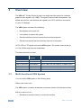
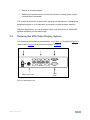
USER MANUAL MODEL: VDS Video Display System P/N: 2900-300285 Rev 2 Contents 1 Introduction 2 2.1 2.2 2.3 3 3.1 3.2 3.3 4 4.1 4.2 4.3 4.4 4.5 4.6 5 5.1 5.2 Getting Started Achieving the Best Performance Safety Instructions Recycling Kramer Products Overview Multi-Functional VDS System Defining the VDS Video Display System Expanding the VDS System Connecting the VDS Connecting an Optional Remote Computer Connecting the CAT 5 Cables Connecting the Power Supply Configuring a CBT Application VDS Detailed Connections Configuring VDS without Remote Computers Operating the VDS system VDS Control Unit Adjusting the Picture Quality 1 2 2 3 3 4 4 5 7 8 8 8 8 8 10 11 13 13 13 6 Technical Specifications 14 Figures Figure 1: Broadcaster Unit Figure 2: Line Splitter Figure 3: Remote Unit Figure 4: Remote Dual Screen Figure 5: Control Unit and Optional Remote Computers Figure 6: Detailed Connections Figure 7 VDS Configuration without Remote Computers Figure 8: Remote Unit Connection Figure 9: Control Unit Panel 5 6 6 6 9 10 11 12 13 VDS – Contents i 1 Introduction Welcome to Kramer Electronics! Since 1981, Kramer Electronics has been providing a world of unique, creative, and affordable solutions to the vast range of problems that confront video, audio, presentation, and broadcasting professionals on a daily basis. In recent years, we have redesigned and upgraded most of our line, making the best even better! Our 1,000-plus different models now appear in 11 groups that are clearly defined by function: GROUP 1: Distribution Amplifiers; GROUP 2: Switchers and Routers; GROUP 3: Control Systems; GROUP 4: Format/Standards Converters; GROUP 5: Range Extenders and Repeaters; GROUP 6: Specialty AV Products; GROUP 7: Scan Converters and Scalers; GROUP 8: Cables and Connectors; GROUP 9: Room Connectivity; GROUP 10: Accessories and Rack Adapters and GROUP 11: Sierra Products. Congratulations on purchasing your Kramer VDS Video Display System, which is ideal for the following typical applications: Digital signage Media distribution Computer-based training VDS - Introduction 1 2 Getting Started We recommend that you: Unpack the equipment carefully and save the original box and packaging materials for possible future shipment Review the contents of this user manual i 2.1 Go to http://www.kramerelectronics.com to check for up-to-date user manuals, application programs, and to check if firmware upgrades are available (where appropriate). Achieving the Best Performance To achieve the best performance: Use only good quality connection cables (we recommend Kramer highperformance, high-resolution cables) to avoid interference, deterioration in signal quality due to poor matching, and elevated noise levels (often associated with low quality cables) Do not secure the cables in tight bundles or roll the slack into tight coils Avoid interference from neighboring electrical appliances that may adversely influence signal quality Position your Kramer VDS away from moisture, excessive sunlight and dust ! 2 This equipment is to be used only inside a building. It may only be connected to other equipment that is installed inside a building. VDS - Getting Started 2.2 Safety Instructions ! 2.3 Caution: There are no operator serviceable parts inside the unit Warning: Use only the Kramer Electronics input power wall adapter that is provided with the unit Warning: Disconnect the power and unplug the unit from the wall before installing Recycling Kramer Products The Waste Electrical and Electronic Equipment (WEEE) Directive 2002/96/EC aims to reduce the amount of WEEE sent for disposal to landfill or incineration by requiring it to be collected and recycled. To comply with the WEEE Directive, Kramer Electronics has made arrangements with the European Advanced Recycling Network (EARN) and will cover any costs of treatment, recycling and recovery of waste Kramer Electronics branded equipment on arrival at the EARN facility. For details of Kramer’s recycling arrangements in your particular country go to our recycling pages at http://www.kramerelectronics.com/support/recycling/. VDS - Getting Started 3 3 Overview The VDS CAT 5 Video Display System is a range extender system for computer graphics video signals up to 1080p. The system, that includes a broadcaster, line splitter and receiver, can distribute the signals over CAT 5 cable from the source to up to 512 displays. The VDS system consists of the following: Broadcaster and control unit Line splitters to expand the system Remote units that connect to each remote monitor/computer Remote dual screen that connects two monitors to the system CAT 5 UTP or FTP cables connect the VDS system. The remote units can be up to 110m (360ft) away from the broadcaster. This table defines the models: Kramer Model 3.1 Kramer Part Number Full Description VDS-RL (0VS21008) 50-0000869011 Minicom VDS CAT5 Video Display Remote Long VDS-B (0VS22011) 50-0000879011 Minicom VDS CAT5 Video Display Broadcaster 8-ports VDS-LS (0VS22012) 50-0000889011 Minicom VDS CAT5 Video Display Line Splitter 8-ports VDS-CU (0VS22076) 50-0000899011 Minicom VDS/AVDS Control unit VDS-RD (0VS23022) 50-0000919011 Minicom VDS CAT5 Video Display Remote Dual Screen VDS-R (0VS23004) Minicom VDS CAT5 Video Display Remote 50-0000909011 Multi-Functional VDS System You can use the VDS system in the following ways: Without the control unit – The VDS system constantly broadcasts a computer screen to all remote monitors. With the control unit to – 4 Broadcast a computer screen to all remote monitors VDS - Overview Darken all remote screens Release the remote screens to allow local monitor viewing (when remote computers are connected) The screen dark function is useful when carrying out maintenance, changing the broadcast program or in a classroom environment to grab students’ attention. With both applications you can broadcast video up to resolutions of 1920x1080 @60Hz depending on the cable length. 3.2 Defining the VDS Video Display System The figures below illustrate the broadcaster unit (Figure 1), line splitter (Figure 2), remote units (Figure 3) and remote dual screen (Figure 4). Power connector System cables 12VDC Monitor VIDEO OUT CONTROL VDS Control Unit SYSTEM VIDEO IN Video cable Figure 1: Broadcaster Unit VDS - Overview 5 Power connector System cables 12VDC SYSTEM IN www.minicom.com SYSTEM OUT System cable from Broadcaster or previous Line Splitter Figure 2: Line Splitter (Optional) Video cable VIDEO IN System cable Picture adjuster PICTURE SYSTEM Side A Side B Monitor Figure 3: Remote Unit VDS Remote Dual Screen To monitors System cable Figure 4: Remote Dual Screen 6 VDS - Overview 3.3 Expanding the VDS System You can expand the VDS system to 512 remote units by having two levels of line splitters. Level 1 line splitters can have eight remote units or line splitters connected. Level 2 line splitters can have eight remote units connected. VDS - Overview 7 4 Connecting the VDS ! 4.1 Warning! In the VDS system the CAT 5 UTP or FTP cables carry electrical power. Connect them only to devices of the VDS family. Do NOT mix them with devices of other families such as AVDS. Damage will occur. To avoid this we recommend you attach the stickers provided to the ends of each cable. Connecting an Optional Remote Computer To work locally, you have the option to connect the remote units to a computer. To do so you need to connect video cable between the remote unit and a computer. Video cables are available from Kramer. 4.2 Connecting the CAT 5 Cables Note: Connect the CAT 5 cables to the broadcaster and line splitter units when the units are powered off. We recommend that you connect the CAT 5 cables BEFORE connecting the power supply. 4.3 Connecting the Power Supply Connect the broadcaster and line splitters to the power supply with the 12 VDC, 2A from the AC/DC adapter provided. The remote units and the remote Dual Screen receive power via the CAT 5 cables from the broadcaster or line splitter. 4.4 Configuring a CBT Application Figure 5 illustrates the VDS configuration with the VDS control unit and the optional remote computers. The remote dual screen has no VGA input and is therefore not suitable for CBT (computer based training) applications. 8 VDS - Connecting the VDS VDS Control Unit Broadcaster Unit CAT5 cables to Remotes or Line Splitters Video cable Broadcaster computer Video cable CAT5 cables to Remotes or Line Splitters Level 1 Optional Remote computer Remote Line Splitter Video cable Optional Remote computer Remote CAT5 cables to Remotes Level 2 Line Splitter Video cable CAT5 cables to Remotes Remote Optional Remote computer Figure 5: Control Unit and Optional Remote Computers VDS - Connecting the VDS 9 4.5 VDS Detailed Connections Figure 6 illustrates the detailed connections of the VDS units. Figure 6: Detailed Connections 10 VDS - Connecting the VDS 4.6 Configuring VDS without Remote Computers Figure 7 illustrates the VDS configuration without optional computers connected to the remote units and the remote dual screen. Connect the broadcaster and line splitters as illustrated in Figure 5. Figure 6 illustrates the detailed connections of the remote unit. Remote Dual Screen CAT5 cables to Remotes or Line Splitters VDS Control Unit Instead of the remote unit, use the remote dual screen to connect two screens to the broadcaster or line Broadcaster Unit splitter via CAT 5 cable. The two Video cable Broadcaster computer screens display the images broadcast by the broadcaster computer. CAT5 cable to Broadcaster or Line Splitter CAT5 cables to Remotes or Line Splitters Remote Line Splitter VDS Remote Dual Screen VDS Remote Dual Screen CAT5 cables to Remotes Line Splitter Remote Figure 7 VDS Configuration without Remote Computers VDS - Connecting the VDS 11 Figure 8 illustrates the remote unit connection. CAT5 cable to Broadcaster or Line Splitter Remote PICTURE Figure 8: Remote Unit Connection 12 VDS - Connecting the VDS 5 Operating the VDS system Once connected the VDS system broadcasts to all remote monitors. 5.1 VDS Control Unit Figure 9 illustrates the panel of the VDS control unit. VDS Control Unit Master to all Dark all To Broadcaster Unit’s Control port MINICOM Figure 9: Control Unit Panel With the VDS control unit, carry out the following functions: 5.1.1 Master to All Press the MASTER TO ALL button to send the broadcaster’s screen to all remote monitors. The LED above the button lights up. 5.1.2 Press the button again to release the remote monitors. Dark All Press the DARK ALL button to darken all remote screens. The LED above the button lights up. 5.2 Press the button again to release the remote screens. Adjusting the Picture Quality Use a small screwdriver to turn the picture adjuster on the remote unit to adjust the picture quality (see Figure 3). VDS - Operating the VDS system 13 6 Technical Specifications INPUTS: 1 VGA on a 15-pin HD connector (broadcaster); 1 twisted pair on an RJ-45 connector (line splitter); 1 twisted pair on an RJ-45 connector, 1 VGA on a 15-pin HD (M) connector (remote); 1 twisted pair on an RJ-45 connector (remote dual screen) OUTPUTS: 8 twisted pair on RJ-45 connectors, 1 VGA on a 15-pin HD connector, 1 control on an 8-pin mini-DIN connector (broadcaster); 1 twisted pair on an RJ-45 connector (line splitter); 1 VGA on a 15-pin HD (F) connector (remote); 2 VGA on 15-pin HD (F) connectors (remote dual screen) RESOLUTION: Up to 1920x1080 @ 60Hz, 1080p SYSTEM CABLE: CAT 5 FTP/UTP cable 2x4x24AWG solid wire conductor MAX. RANGE: 110m (360ft) I/O VIDEO SIGNALS: Analog red, green, blue, 0.7Vpp, 75Ω. SYNC: TTL compatible HORIZONTAL/VERTICAL SYNC POLARITY: Positive/negative POWER SUPPLY 12V DC, 2A (broadcaster, line splitter); from previous unit through CAT 5 cable (remote, remote dual screen) OPERATING TEMPERATURE: 0° to 40°C (32° to 104°F) STORAGE TEMPERATURE: −40° to 70°C (−40° to 158°F) HUMIDITY: 80% non−condensing relative humidity DIMENSIONS: 175mm x 96mm x 42mm (6.9” x 3.8” x 1.7”) (broadcaster); 118mm x 96mm x 42mm (4.6” x 3.8” x 1.7”) (line splitter); 78mm x 62mm x 23mm (3.1” x 2.4” x 0.9”) (remote) ACCESSORIES: Power supply (broadcaster, line splitter) WARRANTY: 3 years Specifications are subject to change without notice at http://www.kramerelectronics.com 14 VDS - Technical Specifications For the latest information on our products and a list of Kramer distributors, visit our Web site where updates to this user manual may be found. We welcome your questions, comments, and feedback. Web site: www.kramerelectronics.com E-mail: [email protected] ! P/N: SAFETY WARNING Disconnect the unit from the power supply before opening and servicing 2900- 300285 Rev: 2