1
Z1900 User Manual
In This Guide
Introduction. . . . . . . . . . . . . . . . . . . . . . . . . . . . . . . . . . . . . . . . . . . 1
Choosing a location for the Network Access Unit . . . . . . . . . . . . . . 6
Mounting the Network Access Unit . . . . . . . . . . . . . . . . . . . . . . . . . 8
Mounting the Coverage Unit . . . . . . . . . . . . . . . . . . . . . . . . . . . . . 12
Trouble-Shooting . . . . . . . . . . . . . . . . . . . . . . . . . . . . . . . . . . . . . 13
Z1900 System Specifications . . . . . . . . . . . . . . . . . . . . . . . . . . . . 14
Limited Warranty . . . . . . . . . . . . . . . . . . . . . . . . . . . . . . . . . . . . . . 15
FCC, Health, and Authorization for Use . . . . . . . . . . . . . . . . . . . . . 17
Technical Support
Z1900 serial numbers must be available to authorize technical support and/or
to establish a return authorization for defective units. The serial numbers are
located on the back of the Coverage Unit and the Network Access Unit, as
well as on the box in which they were delivered. Additional support information
may be obtained by accessing the Spotwave Wireless Inc. website at
www.spotwave.com/z1900
Important Safety Information
Warning! For your safety, beware of power lines and
ensure appropriate safety measures are maintained at all
times during the installation of the Z1900 equipment. If
equipment not shipped with the Z1900 system is to be
used during installation or mounting, follow all equipment
manufacturer’s instructions in proper use to ensure injury
is avoided.
Warning! For your safety, do not connect or disconnect
the RF coaxial cable from the Network Access Unit or
Coverage Unit while the power is connected to the
Coverage Unit. Power to the Network Access Unit is
supplied from the Coverage Unit through the coaxial
cable. Connecting or disconnecting the coaxial cable
while the system is powered may result in electric shock or
damage to the equipment.
INTRODUCTION
Introduction
Congratulations! You have purchased one of the finest personal wireless coverage systems available on
the market. The content of this manual complements the Z1900 Quick Install Guide and provides specific
details that may be referred to if necessary during installation of a Z1900 coverage system.
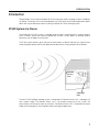
Z1900 System at a Glance
The purpose of the Z1900 system is to enable personal wireless communications in specific locations
within a wireless service area where cell phones do not work, or work poorly, for example inside a
basement, or at the edge of a service area.
The Z1900 system receives signals from one or more wireless cel towers and relays the signal to areas
where cell phones do not work or work poorly due to obstructions or the remoteness of the location.
Network
Access
Unit
Coverage
Unit
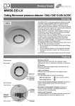
The basic Z1900 intelligent coverage system is comprised of a Network Access Unit, a Coverage Unit
and a power supply. The Network Access Unit is the outward facing part of the system that
communicates with the base station or cell tower. The Network Access Unit is connected (via coaxial
cable) to the Coverage Unit which provides wireless coverage to indoor areas.
1
INTRODUCTION
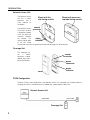
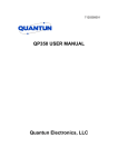
Network Access Unit
The Network Access
Unit has a coaxial
connector and a
status indicator on
the bottom.
Mount with this
side facing outside
Mount with arrows on
top label facing outside
coaxial
The Network Access connector
Unit’s built-in antenna
is located on the back
of the unit where the
mounting
keyholes
status
are located. This
antenna side (or back
indicator
of the unit) should
face outside, away from the general area where the Coverage Unit will be located.
Coverage Unit
The Coverage Unit
has
a
coaxial
connector, a power
adapter port and a
power ON indicator.
coaxial
connector
power
connector
power
indicator
cover
Z1900 Configuration
The basic Z1900 system configuration is one Network Access Unit connected with a coaxial cable to a
Coverage Unit which is connected to an AC adapter that supplies power to both units.
Network Access Unit
power cable
coaxial cable
Coverage Unit
2
Z1900 SETUP - COMPONENTS OF THE SYSTEM
Z1900 Setup
Z1900 is a simple-to-install system that includes everything you need. The basic steps for setting up your
system are:
a. Locate the best signal within 35 feet of the area requiring coverage.
b. Connect the Network Access Unit to the Coverage Unit and power the system.
c. Position and mount the Network Access Unit.
d. Position and mount the Coverage Unit.
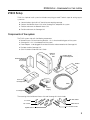
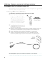
Components of the system
The Z1900 system ships with the following components:
z Network Access Unit and mounting brackets - this is the outward facing part of the system.
z Coverage Unit - this is the indoor part of the system.
z Power Adapter - to be plugged into an electrical outlet and connected to the Coverage Unit.
z Desktop stand for Coverage Unit.
z
Quick Installation Guide and User’s Guide.
Network
Access
Unit
Desktop Stand
for Coverage Unit
Mounting Brackets
for Network
Access Unit
Guides
Cover for
Coverage Unit
Cable
Power
Supply
Coverage Unit
The mounting kit for the Network Access Unit and Coverage Unit also includes:
½" screws
1¼" screws
drywall anchors
90º cable elbow
cable wrench
1¼" concrete screws
3
Z1900 SETUP - BEFORE YOU BEGIN
Before you begin
The following are general considerations and preparations that should be looked at before installing the
Z1900 coverage system.
Signal Strength
The Z1900 system brings signals from an area of
adequate coverage to an area with poor or nonexistent coverage. It is the Network Access Unit which
captures a good signal, and the Coverage Unit that
provides the signal to the area with poor cell phone
coverage. The Network Access Unit can be mounted
inside or outside, as long as it is in an area where your
cell phone works.
Generally, the better your cell phone works at the
location the Network Access Unit is to be mounted,
the better the system will perform.
Network Access Unit Location and Height
Locating the Network
Access Unit in a window
or on an exterior wall,
away from metal siding
and as high as possible
will usually provide better
performance.
4
Locate the Network
Access Unit where
your mobile phone
works best (the
strongest signal)
Z1900 SETUP - BEFORE YOU BEGIN
Avoid obstructions
General placement of the
Network Access Unit and
Coverage Unit must be in
unobstructed areas.
Coverage Unit Placement
For example, the Coverage
Unit should not be placed
on a wall behind any type of
furniture (behind items such
as metal filing cabinets
would be a particularly poor
location).
Similarly, the back of the Network
Access Unit should not be
directly facing any type of metal
structures such as sheds or
aluminum siding.
metal
siding
The back of the Network
Access Unit should not
face any metal structure
Proximity to power outlet
The length of the AC adapter cable requires the Coverage Unit to be located within 6 feet of a power
outlet.
Distance between Network Access Unit and Coverage Unit
Although you should separate the Network Access Unit and Coverage Unit as much as possible to
optimize performance (the minimum recommended separation is 10 feet), you are limited by the length of
the included 35 ft coaxial cable.
5
Z1900 SETUP - CHOOSING A LOCATION FOR
THE
NETWORK ACCESS UNIT
Choosing a location for the Network Access Unit
The Network Access Unit is the outward facing unit. It is the unit that picks up the signal from and
communicates with the service provider’s cel tower.
Positioning the Network Access Unit Indoors
The following outlines the procedure for locating a Network Access Unit indoors.
1. Use your mobile phone to identify the inside
location with the strongest received signal
(usually near an exterior wall). If no adequate
signal is available indoors then it may be
necessary to try an outside location (such as
an outside roof or external wall) where a
stronger signal is received (see Positioning the
Network Access Unit Outdoors on page 8).
Identify the
location with the
strongest signal
2. Temporarily position the Network Access Unit
(but do not physically mount it) in the location
that showed the strongest signal.
3. Position the Coverage Unit (but do not physically mount it) in the area that requires coverage. The
Coverage Unit must also be located as far away as possible from the Network Access Unit.
4. Use your mobile phone to note the signal level (number of bars) at the Coverage Unit.
5. Connect the Coverage Unit to the Network Access Unit with the provided coaxial cable.
Use the wrench provided to tighten the coaxial connectors, but be careful not to overtighten.
coaxial cable
Note: To avoid potential signal loss, ensure there are no sharp bends or kinks in the cable.
6
Z1900 SETUP - CHOOSING A LOCATION FOR
THE
NETWORK ACCESS UNIT
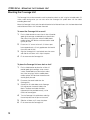
6. Connect the power supply to the Coverage Unit, and then plug the adapter into an power outlet.
Note: Use only the power
supply provided with the
Z1900 system.
Connecting any other power
supply may damage the unit
and cause it to fail.
7. Verify that the Z1900 system is working by noting the signal level (number of bars on your mobile
phone) near the Coverage Unit and comparing it to that measured before the system was turned on
in step 4.
IMPORTANT: The direction that the Network Access Unit is facing is a factor in the quality of the
coverage you will receive from your Z1900 system. You may have to try aiming the Network Access
Unit in different directions or facing different surfaces (wall or windows) to achieve optimal coverage.
8. Proceed to Mounting the Network Access Unit in the location and direction that showed the best
coverage.
7
Z1900 SETUP - MOUNTING THE NETWORK ACCESS UNIT
Positioning the Network Access Unit Outdoors
The Network Access Unit can also be mounted outside when no indoor location with an adequate signal
level can be found. If you are installing the Network Access Unit outdoors (especially in a remote area),
then an effort should be made to mount the unit as high as possible.
Warning! An outdoor mounted Network Access Unit must be properly grounded in accordance with local
building and electrical code requirements and must comply with both local and national regulations.
Mounting the Network Access Unit
Mount the Network Access Unit only after the optimal location for the unit has been determined (see
“Choosing a location for the Network Access Unit”). The Z1900 system ships with basic hardware for
mounting the Network Access Unit to an inside or outside wall.
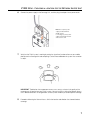
Flush mounting the Network Access Unit to an inside wall
To mount the Network Access Unit flush to an inside wall
NOTE: To enhance performance, avoid mounting the Network Access Unit directly over a wall stud.
1. Fasten two 1¼" screws to the wall, 5½ inches vertically apart.
Leave approximately a ¼ inch gap between the head of the
screws and the wall.
2. Align the Network Access Unit’s two keyholes over the screws
and slide the unit down until it snaps into place.
For easy drywall installation, you can locate where the drywall anchors
need to be placed by pressing the Network Access Unit against the
drywall. Tiny marks will be left in the wall and the screws or drywall
anchors should be installed between these marks.
8
Z1900 SETUP - MOUNTING
THE
NETWORK ACCESS UNIT
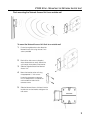
Flush mounting the Network Access Unit to an outside wall
To mount the Network Access Unit flush to an outside wall
1. Fasten the angle bracket to the side of the
Network Access Unit using the two ½ inch
screws provided.
2. Back-off the side screws to the point
where the bracket can easily slide off the
unit through the keyholes of the bracket.
3. Slide the angle bracket off the Network
Access Unit.
4. Mount the bracket to the wall using
the appropriate 1¼ inch screws.
If mounting to cement or concrete,
first use the bracket as a template to
mark and drill the holes for the
concrete screws.
5. Slide the Network Access Unit back into the
keyhole slots on the bracket and tighten the
two screws.
9
Z1900 SETUP - MOUNTING THE NETWORK ACCESS UNIT
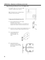
Edge Mounting the Network Access Unit (indoor only)
The Network Access Unit can also be edge
mounted to a window frame or inside wall.
Note: The Network Access Unit edge bracket is
designed for indoor mounting only.
To edge mount the Network Access Unit
1. Mount the edge bracket to the wall through
the keyholes, using 1¼"screws.
If mounting to cement or concrete, first use the bracket as a
template to mark and drill the holes for the concrete screws.
2. Back-off the screws to the point where the edge bracket can just
slide off the wall and then remove the bracket from the wall.
3. Fasten the edge bracket to
the Network Access Unit
using the provided ½ inch
screws.
4. Align the Network Access
Unit/Bracket assembly keyholes
over the two wall screws and slide
down into place.
10
Z1900 SETUP - CHOOSING A LOCATION FOR
THE
COVERAGE UNIT
Choosing a location for the Coverage Unit
The blue indicator on the bottom of the Network
Access Unit is an indicator of the level of RF
isolation between the Network Access Unit and
the Coverage Unit.
If the indicator is a solid blue, then there is enough
RF isolation (between the Network Access Unit
and Coverage Unit) to provide the best coverage
possible.
Network
Access Unit
status indicator
If the indicator is flashing, the system is still
providing coverage, but the performance is
reduced due to inadequate spacing between the
Coverage Unit and Network Access Unit. The
longer the indicator is on during the on/off flash
cycle, the better the RF isolation and coverage.
Positioning the Coverage Unit
Coverage Unit
1. Ensure that the Network Access Unit is
mounted and connected with the coaxial
cable to the Coverage Unit. The Coverage
Unit should also be located (but not mounted) in the area that needs coverage and powered by the
provided AC adapter.
2. If the Network Access Unit indicator is a solid blue then the coverage is good and you should skip
directly to mounting the coverage unit in this location. See Mounting the Coverage Unit on page 12.
3. If the indicator is flashing, then the performance is
reduced, but may be improved by moving the
Coverage Unit to another location within the area
requiring coverage.
Try moving the Coverage Unit to a location where the
indicator on the Network Access Unit will remain a
solid blue. If that is not possible, then the location
where the indicator remains on the longest (during
the on/off flash cycle) is where the Coverage Unit
should be mounted.
best
good
poor
4. Make a test call with your mobile phone to confirm
coverage improvement.
5. Once the location for the Coverage Unit has been
determined, proceed to Mounting the Coverage Unit
on page 12.
Level of system performance is indicated
by the length of time the indicator
(on the Network Access Unit) remains
on during the on/off flash cycle.
11
Z1900 SETUP - MOUNTING THE COVERAGE UNIT
Mounting the Coverage Unit
The Coverage Unit can be mounted to a wall or placed on a desk or shelf using the included cradle. If it
makes cable routing easier, you can also mount the Coverage Unit upside down with the cables
extending downward.
Mount the Coverage Unit only after the optimal location for the Network Access Unit has been determined
and the Network Access Unit has been mounted.
To mount the Coverage Unit on a wall
1. Find a suitable location to mount the unit that will provide
good signal coverage, not blocked by any obstructions
and at least 3 feet away from where a mobile phone,
cordless phone, WiFi device or microwave oven would
typically be used.
2. Fasten two 1¼" screws to the wall, 3¼ inches apart.
Leave approximately a ¼ inch gap between the head of
the screws and the wall.
3. Align the Coverage Unit’s two keyholes over the screws
and slide the unit down until it snaps into place.
4. Fit the cover onto the Coverage Unit.
To place the Coverage Unit on a desk or shelf
1. Find a suitable location to place the unit that will
provide good signal coverage, not on a metal
surface, not blocked by any obstructions and at
least 3 feet away from where a mobile phone,
cordless phone, WiFi device or microwave oven
would typically be used.
2. Disconnect the coaxial cable from the
Coverage Unit.
3. Connect the 90º cable elbow to the Coverage
Unit and connect the coaxial cable to the
elbow. The elbow and cable should be
tightened (with the provided wrench), just be
careful not to overtighten.
4. Turn the Coverage Unit upside down and align
the two keyholes over the pins on the stand.
5. Slide the unit down until it snaps into place.
6. Fit the cover onto the Coverage Unit.
12
TROUBLE-SHOOTING
Trouble-Shooting
1. Status: The system is not providing any coverage and the indicator on the bottom of the Network
Access Unit is flashing red.
A flashing red indicator means that the system is in mute mode, which can be caused by a mobile
phone being too close to the Coverage Unit or the Coverage Unit being too close to the Network
Access unit.
After repeated muting, the system will stay in mute mode for an extended period of time before
attempting to re-initialize. Turn the system off and then back on to reset the system.
Action: If possible, move the Coverage Unit farther away from the Network Access Unit and ensure
that your cell phone is not closer than 2 feet from the Coverage Unit.
2. Status: The system is not providing any coverage and the indicator on the bottom of the Network
Access Unit is solid red.
A solid red indicator means a hardware fault condition.
Action: Turn the system off, check the cable connections and then turn back on. If the indicator is
still solid red, then the Z1900 system should be returned to the point of sale for exchange.
3. Status: The blue status indicator on the Network Access Unit is flashing.
Action: The system is functioning properly, but with reduced coverage due to poor isolation
between the Network Access Unit and the Coverage Unit. Try moving the Coverage Unit to a
location where the indicator will remain a solid blue. If that is not possible, then the location where
the indicator remains on the longest (during the on/off flash cycle) is where the Coverage Unit
should be mounted.
4. Status: The indicator on the Coverage Unit is not illuminating.
Action: Ensure that the power supply is connected to the Coverage Unit and the power supply is
plugged into a working electrical outlet.
If the indicator is still not illuminating, then return the Z1900 system to the point of sale for exchange.
5. Status: The indicator on the Network Access Unit is not illuminating.
Action: Ensure the following:
z
z
The cable from the Network Access Unit is properly connected to the Coverage Unit.
The Coverage Unit is powered (the indicator is illuminated).
If the indicator is still not illuminating, then return the Z1900 system to the point of sale for exchange.
6. Status: The coverage area around the Coverage Unit shrinks after a long period of reliable operation.
Action: This is most likely due to a network change or man made environmental influences such as
a large building being erected somewhere in between the Network Access Unit and the location the
Network Access Unit is receiving a signal from. Repeating the install procedure may improve system
performance (i.e. re-aligning and mounting the Network Access Unit in a direction that provides
greater signal strength).
7. Status: My phone does not work at the location I would like to install the Network Access Unit.
Action: Try positioning the Network Access Unit outside as high as possible.
13
Z1900 SYSTEM SPECIFICATIONS
Z1900 System Specifications
Note: Spotwave has the right to change specifications without notice.
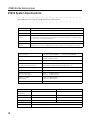
NAU Status Color
Status
Off
No power. Product is not providing any coverage.
Blue
Power on, normal operation.
Blue
flashing
Power on and system is functioning, but with reduced coverage due to poor isolation between
the Network Access Unit and the Coverage Unit. The longer the indicator is on during the flash
cycle, the better the system performance.
Red
Hardware fault condition. System needs to be replaced.
Red
flashing
Mute mode, (could indicate that a mobile phone is too close to the Coverage Unit or the Coverage Unit is too close to the Network Access unit). Product is not providing any coverage.
Frequency Bands
PCS Uplink: 1850-1910 MHz
Networks Supported
TDMA / GSM / GPRS / EDGE / UMTS / IS-95 / CDMA / 1XRTT /
1XEVDO / HSDPA / IS-136
Typical Coverage Area
up to 2,500 sq. ft (230 m²)
System Gain
(fully adaptive, includes antenna)
Uplink: 0 to +63 dB maximum (including 6dB nominal cable loss)
Downlink: 0 to +63 dB maximum (including cable loss)
System Stability Margin
> 10 dB
Downlink Operating Range
-95 to - 40 dBm
Maximum Input Level
(receive isotropic power)
Uplink:
-10 dBm maximum
Downlink: -40 dBm maximum
Output Level -EIRP
(fully adaptive)
Uplink: +27 dBm maximum
Downlink: 3 dBm maximum
Power Consumption
10 W
Network Access Unit
Coverage Unit
-40° to +131° F (-40° to +55° C)
+32° to +104° F (0° to +40° C)
Size
7 x 7 x 2.5 in.
2.75 x 6 x 1.25 in.
Weight
2 lbs.
0.5 lb.
RF Connectors
Type F: Coverage Port
Type F: Network Access Port
RF Cable
35 ft of miniature coaxial cable
Power Supply
Universal power adapter (input 90 - 240 VAC, 47 -63 Hz; output 9 V, 10 W)
Operating
Temperature
14
Downlink: 1930-1990 MHz
LIMITED WARRANTY AND LIMITATION OF LIABILITY:
LIMITED WARRANTY AND LIMITATION OF LIABILITY:
1. What is Covered and for How Long? Spotwave Wireless Inc. ("Spotwave") warrants to the original Purchaser that
the Spotwave Z1900 System (the "System") is free from defects in material and workmanship under normal use and
service for a period of 12 months from the date of shipment from Spotwave (the "Limited Warranty Period").
2. What is not covered?
This Limited Warranty is conditioned upon proper use of the System by the Purchaser. This
Limited Warranty does not cover (and will become null and void in the event of): (a) defects or damage resulting from
accident, misuse, abuse, neglect, unusual physical, electrical or electromechanical stress, modification of the System or
any part thereof, or cosmetic damage; (b) removal, alteration or defacing of the serial number or other identifying marks
on the System; (c) all plastic surfaces and other externally exposed components that are scratched or damaged due to
normal use; (d) malfunctions resulting from the use of the System in conjunction with accessories, products or (ancillary)
or peripheral equipment not provided by Spotwave; or (e) defects or damage from unauthorized or improper testing,
operation, maintenance, installation, servicing or adjustment of the System. Any repairs or replacements provided by
Spotwave outside of the Limited Warranty Period (including repairs to or replacement after the end of the Warranty
Period), or in excess of the services provided during the Limited Warranty Period, will subject to Spotwave's then
prevailing rates.
3. What are Spotwave's Obligations and how do you make a claim? During the Limited Warranty Period, Spotwave
will repair or replace, at Spotwave's sole option, without charge to Purchaser, any defective component of the System,
provided that the System is returned promptly upon discovery of the defect and during the Limited Warranty Period. To
obtain service, Systems must be returned to an authorized service facility in the original packaging or packaging
adequate for shipping, accompanied by Purchaser's sales receipt or comparable substitute proof of sale showing the
date of purchase and the serial number of the System. A valid RMA is required prior to any return.
To locate your nearest authorized service facility, call Spotwave Customer Service at 1-877-610-9586. Spotwave may, at
Spotwave's sole option, use rebuilt, reconditioned, or new parts or components when repairing any System or replace a
System with a rebuilt, reconditioned or new System. Repaired Systems will be warranted for a period equal to the
remainder of the original Limited Warranty Period for the original System or for 90 days, whichever is longer. All replaced
parts, components, boards or equipment shall become the property of Spotwave. If Spotwave determines that any
System is not covered by this Limited Warranty, the Purchaser must pay the costs for all parts, shipping, and labor
charges for the repair or return of such System.
4. What are the Limits on Spotwave's Liability?
EXCEPT FOR THE WARRANTY IN PARAGRAPH 1, THE
SYSTEMS AND ANY ASSOCIATED SERVICES ARE PROVIDED BY SPOTWAVE ON AS 'AS IS' BASIS AND THERE ARE
NO OTHER REPRESENTATIONS, WARRANTIES OR CONDITIONS, EXPRESS OR IMPLIED, WRITTEN OR ORAL,
ARISING BY STATUTE, OPERATION OF LAW, COURSE OF DEALING, USAGE OF TRADE OR OTHERWISE,
REGARDING THEM OR ANY OTHER PRODUCT OR SERVICE PROVIDED HEREUNDER OR IN CONNECTION
HEREWITH BY SPOTWAVE. SPOTWAVE DISCLAIMS ANY IMPLIED WARRANTIES OR CONDITIONS OF DURABILITY,
MERCHANT ABILITY, MERCHANTABLE QUALITY, SATISFACTORY QUALITY, NON-INFRINGEMENT OR FITNESS FOR
A PARTICULAR PURPOSE. SPOTWAVE DOES NOT REPRESENT OR WARRANT THAT THE SYSTEMS WILL MEET
ANY OR ALL OF PURCHASERS' PARTICULAR REQUIREMENTS, THAT THE SYSTEMS WILL OPERATE ERROR-FREE
OR UNINTERRUPTED OR THAT ALL ERRORS OR DEFECTS IN THE SYSTEMS CAN BE FOUND TO BE CORRECTED.
System performance is dependant upon the performance and availability of services or technology provided by third
parties and Spotwave is not responsible for service continuity and reliability, reception, or other performance related
limitations associated with use of the Systems. NO AGREEMENTS VARYING OR EXTENDING THE TERMS OF THIS
LIMITED WARRANTY WILL BE BINDING ON SPOTWAVE UNLESS IN WRITING AND SIGNED BY AN AUTHORIZED
SIGNING OFFICER OF SPOTWAVE THIS LIMITED WARRANTY SHALL NOT EXTEND TO ANYONE OTHER THAN THE
ORIGINAL PURCHASER OF THE SYSTEM. SPOTWAVE'S MAXIMUM AGGREGATE LIABILITY TO PURCHASER SHALL
NOT EXCEED THE AMOUNTS PAID BY PURCHASER FOR THE SYSTEM GIVING RISE TO THE CLAIM. SPOTWAVE
SHALL NOT BE LIABLE FOR ANY SPECIAL, INCIDENTAL, CONSEQUENTIAL, INDIRECT OR SIMILAR DAMAGES,
LOSS OF USE, DATA OR PROFITS, DAMAGES TO PURCHASER'S PROPERTY, OR INJURY TO PURCHASER OR
OTHERS ARISING OUT OF THE USE, MISUSE OR INABILITY TO USE ANY SYSTEM, WHETHER OR NOT SUCH
DAMAGE ARISES OUT OF CONTRACT OR TORT (INCLUDING WITHOUT LIMITATION, NEGLIGENCE) OR CLAIMS BY
A THIRD PARTY, EVEN IF SPOTWAVE HAS BEEN ADVISED OF SUCH DAMAGES OR THEY ARE FORESEEABLE.
5. This Limited Warranty allocates risk between Purchaser and Spotwave, and the Spotwave System pricing
reflects this allocation of risk and the limitations of liability contained in this Limited Warranty. The agents, employees,
distributors, dealers or representative of Spotwave are not authorized to make modifications to this Limited Warranty, or
make additional warranties binding on Spotwave. Accordingly, additional statements such as advertising or
presentations, whether oral or written, do not constitute warranties by Spotwave and should not be relied upon.
15
LIMITED WARRANTY AND LIMITATION OF LIABILITY:
OWNERSHIP AND RISK OF LOSS:
6. Who Owns the rights in the System?
The System is protected by Canadian, US and international patent and
copyright law and other intellectual property protection laws and treaties. Purchaser acknowledges that Spotwave and its
licensors are the owner of all intellectual property, including, without limitation, patents and copyright, relating to the
System and the trademarks used in association with the System. Purchaser agrees that it will not (and will not attempt
to) modify, prepare derivative works of, reverse engineer, decompile, disassemble, or other attempt to derive the source
code of any software contained within the System.
7. Who bears the Risk of Loss?
Risk of loss for the System passes to Purchaser upon the delivery to Purchaser or
to a carrier for shipment, which ever is earlier. Title to the Systems (excluding any software) will pass upon payment in full
for the Systems. Title to any software shall always remain with Spotwave or its licensors. As security for payment,
Purchaser grants to Spotwave a purchase money security interest in the Systems (together with any proceeds, including
insurance proceeds) and agrees that a copy of this letter of agreement or any other appropriate document may be
registered as required to perfect the security interest granted. Systems may be resold by Purchaser in normal course of
business, but until paid for in full, Purchaser will not pledge or otherwise encumber the Systems, Purchaser agrees to
immediately report to Spotwave, (i) any seizure or attachment of the Systems by creditors; (ii) any petition in bankruptcy,
insolvency, receivership or similar proceedings filed by, or against Purchaser; or (iii) any arrangement, composition or
similar agreement for the benefit of creditors. Systems held for Purchaser by Spotwave are at Purchaser's sole risk and
expense.
OTHER TERMS:
8. What terms govern our relationship?
These terms and any software license or warranty documentation
accompanying the Systems constitute the complete and exclusive statement of the terms and conditions between us
regarding the Systems and cannot be altered, amended or modified except in writing executed by Spotwave. This letter
of agreement and any disputes arising hereunder shall be governed by and interpreted in accordance with the laws of the
Province of Ontario, Canada. The United Nations Convention on Contracts for the International Sale of Goods and any
legislation implementing such Convention, if otherwise applicable is expressly excluded. Any terms and conditions of any
purchase order or other instrument issued by Purchaser which are in addition to or inconsistent with the terms and
conditions of this letter of agreement shall not be binding and shall not apply, even if accepted by Spotwave.
MANUAL DISCLAIMER
Product specifications, pricing, packaging, technical support and information ("Specifications") and all claims, features,
representations, and/or comparisons provided are correct to the best of our knowledge on the date of publication, but
may contain errors or omissions and are subject to change without notice.
INFORMATION IS PROVIDED BY SPOTWAVE WIRELESS INC. ON AN "AS IS" BASIS, WITHOUT ANY OTHER
WARRANTIES OR CONDITIONS, EXPRESS OR IMPLIED, INCLUDING, BUT NOT LIMITED TO, WARRANTIES OF
MERCHANTABLE QUALITY, SATISFACTORY QUALITY, MERCHANTABILITY OR FITNESS FOR A PARTICULAR
PURPOSE, OR THOSE ARISING BY LAW, STATUTE, USAGE OF TRADE, COURSE OF DEALING OR OTHERWISE. THE
ENTIRE RISK AS TO THE RESULTS OF THE INFORMATION PROVIDED IS ASSUMED BY YOU. WE SHALL HAVE NO
LIABILITY TO YOU OR ANY OTHER PERSON OR ENTITY FOR ANY INDIRECT, INCIDENTAL, SPECIAL, OR
CONSEQUENTIAL DAMAGES WHATSOEVER, INCLUDING, BUT NOT LIMITED TO, LOSS OF REVENUE OR PROFIT,
LOST OR DAMAGED DATA OR OTHER COMMERCIAL OR ECONOMIC LOSS, EVEN IF WE HAVE BEEN ADVISED OF
THE POSSIBILITY OF SUCH DAMAGES, OR THEY ARE FORESEEABLE. WE ARE ALSO NOT RESPONSIBLE FOR
CLAIMS BY A THIRD PARTY. OUR MAXIMUM AGGREGATE LIABILITY TO YOU AND THAT OF OUR DEALERS AND
SUPPLIERS SHALL NOT EXCEED FORTY DOLLARS. SOME STATES/COUNTRIES DO NOT ALLOW THE EXCLUSION
OR LIMITATION OF LIABILITY FOR CONSEQUENTIAL OR INCIDENTAL DAMAGES, SO THE ABOVE LIMITATIONS MAY
NOT APPLY TO YOU. All product, font and company names are trademarks or registered trademarks of their respective
owners.
16
FCC Declaration of Conformity
Health and Authorization for Use
This equipment complies with CFR 47, Part 15.19 of the
FCC rules. Operation of the equipment is subject to the
following conditions:
Z1900 equipment emits radio frequency electromagnetic
energy to enhance signals received by mobile devices for
in-building coverage. However, the energy level of these
emissions is far less than the electromagnetic energy
emitted by other wireless devices.
This device may not cause harmful interference; and
This device must accept any interference received,
including interference that may cause undesired
operation.
Information to the User for Class B Digital
Equipment
This equipment has been tested and found to comply with
limits for a Class B digital device, pursuant to part 15 of the
FCC rules. These limits are designed to provide reasonable
protection against harmful interference in a residential
installation. This equipment generates, uses and can
radiate radio frequency energy and, if not installed and
used in accordance with the instructions, may cause
harmful interference to radio communications. However,
there is no guarantee that interference will not occur in a
particular installation.
If this equipment does cause interference to radio or
television reception, which can be determined by turning
the equipment off and on, the user is encouraged to try to
correct the interference by one or more of the following
measures:
Reorient or relocate the receiving antenna;
Increase the separation between the equipment and
receiver;
Connect the equipment into an outlet on a circuit
different from that to which the receiver is connected;
Consult the dealer or an experienced radio/TV
technician for help.
FCC Regulatory Compliance
Caution! To maintain compliance with the FCC's RF
exposure guidelines, this equipment shall be installed and
operated with a minimum distance of 20cm between the
radiator (Coverage Unit or Network Access Unit) and your
body. Unauthorized modification of any hardware and
attachment may violate FCC regulations.
Warning! The use of the supplied power adapter is
required in order to meet FCC emission limits and to
prevent interference to nearby radio or television reception.
It is essential that only the supplied power cord be used.
You are cautioned that changes or modifications not
expressly approved by the party responsible for
compliance could void your authority to operate the
equipment.
Maximum Permissible Exposure Statement
The Z1900 system is a low power repeater for in-door
coverage. The electromagnetic radiation emitted is much
less than that specified by the FCC. The products have
been evaluated under the FCC Bulletin Office of
Engineering Technology 65c - Evaluating Compliance with
FCC Guidelines for Human Exposure to Radio Frequency
Electromagnetic Fields. This equipment is compliant to the
requirements as set forth in the Code of Federal Regulation
47, section 2.1091 (Radio frequency radiation exposure
evaluation), section 1.1310 (Radio frequency Radiation
Exposure Limits). Nevertheless, this equipment shall be
installed and operated with a minimum distance of 20cm
between the radiator and your body. Use of this equipment
in a body-worn manner is strictly prohibited.
This equipment has been tested and complies with the
following FCC requirements:
Safety Code 6 - Industry Canada Requirement
FCC Part 24, subpart E: Broadband PCS.
FCC Part 15, subpart C - Intentional radiators.
This equipment has been evaluated for radio frequency
Radiation limits in accordance with the Safety Code 6 Limits of Human Exposure to Radio frequency
Electromagnetic Fields in the Frequency Range from 3KHz
to 300GHz. The equipment is compliant to the safety code
6 requirements for the radiation limits as specified in
sections 2.1 and sections 2.2.
Industry Canada Compliance
This equipment has been tested and complies with the
following requirements:
RSS - 131 - Zone Enhancers for Land Mobile
Service.
ICES-003, Issue 4 - Interference Causing Equipment
Standard - Digital Apparatus
Safety Information
The CSA mark indicates that this Equipment meets the
CAN/CSA C22.2 N° 60950-00 and ANSI/UL Std N°
60950-00 - Safety of Information Technology Equipment.
Regulatory Notes and Statements
© 2006 Spotwave Wireless Inc. All rights reserved.
Z1900, Spotwave Wireless and Spotwave Wireless logo are trademarks of Spotwave Wireless Inc.
Patents pending.
Product and service availability subject to change without notice.
Spotwave Wireless, Inc., 1 Hines Road, Suite 204, Ottawa ON K2K 3C7 Canada
www.spotwave.com/z1900
Printed in Canada
780-00042-01-01