1
®
SpotCell 200 Series User Manual
SpotCell 200, 211, 212 & 263
Technical Support
The SpotCellTM serial number must be available to authorize technical support and/or to
establish a return authorization for defective units. The serial number is located on the back
of the Coverage Unit (CU) and Donor Unit (DU) as well as the box in which they were
delivered. Additional support information may be obtained by accessing the
SpotwaveWireless Inc. website at www.spotwave.com. To contact support by telephone,
call your local Spotwave vendor, or if you are unable to reach your vendor, contact Spotwave
Wireless at 1-877-610-9586.
Important Safety Information
Warning! For your safety, beware of power lines and ensure appropriate safety measures are
maintained at all times during the installation of the SpotCell equipment. If equipment not
shipped with the SpotCell system is to be used during installation or mounting, follow all
equipment manufacturer’s instructions in proper use to ensure injury is avoided.
The DU and CU of the SpotCell are low power transmitters. As with a cell phone antenna,
avoid unneccessary contact with the front of the units after installed. Mount the units in a
location where people will not approach within 1 meter of the front of the DU and 20
centimeters in front of the CU.
When deploying the extended coverage antenna, there must be a minimum separation of
10cm between the main CU and the extended coverage antenna with the antennas facing in
opposite directions. The extended coverage antenna should be mounted in locations where
people will not approach within 20cm in front of the antenna.
This manual outlines installation instructions and the appendix offers practical safety tips
(see page 47 entitled ‘Safety Hints’).
If you are not sure about a safe installation, do not attempt to install it yourself. Call a
professional installer for help.
Spotwave Wireless Inc.
i
TECHNICAL SUPPORT
LIMITED WARRANTY AND LIMITATION OF LIABILITY:
1. What is Covered and for How Long?
Spotwave Wireless Inc. ("Spotwave") warrants to the original Purchaser that the Spotwave
SpotCell System (the "System") is free from defects in material and workmanship under normal use and service for a period of 12 months
from the date of shipment from Spotwave (the "Limited Warranty Period").
2. What is not covered?
This Limited Warranty is conditioned upon proper use of the System by the Purchaser. This Limited Warranty
does not cover (and will become null and void in the event of): (a) defects or damage resulting from accident, misuse, abuse, neglect,
unusual physical, electrical or electromechanical stress, modification of the System or any part thereof, or cosmetic damage; (b) removal,
alteration or defacing of the serial number or other identifying marks on the System; (c) all plastic surfaces and other externally exposed
components that are scratched or damaged due to normal use; (d) malfunctions resulting from the use of the System in conjunction with
accessories, products or (ancillary) or peripheral equipment not provided by Spotwave; or (e) defects or damage from unauthorized or
improper testing, operation, maintenance, installation, servicing or adjustment of the System. Any repairs or replacements provided by
Spotwave outside of the Limited Warranty Period (including repairs to or replacement after the end of the Warranty Period), or in excess of
the services provided during the Limited Warranty Period, will subject to Spotwave's then prevailing rates.
3. What are Spotwave's Obligations and how do you make a claim? During the Limited Warranty Period, Spotwave will repair or replace,
at Spotwave's sole option, without charge to Purchaser, any defective component of the System, provided that the System is returned
promptly upon discovery of the defect and during the Limited Warranty Period. To obtain service, Systems must be returned to an
authorized service facility in the original packaging or packaging adequate for shipping, accompanied by Purchaser's sales receipt or
comparable substitute proof of sale showing the date of purchase and the serial number of the System. A valid RMA is required prior to
any return.
To locate your nearest authorized service facility, call Spotwave Customer Service at 1-877-610-9586. Spotwave may, at Spotwave's sole
option, use rebuilt, reconditioned, or new parts or components when repairing any System or replace a System with a rebuilt, reconditioned
or new System. Repaired Systems will be warranted for a period equal to the remainder of the original Limited Warranty Period for the
original System or for 90 days, whichever is longer. All replaced parts, components, boards or equipment shall become the property of
Spotwave. If Spotwave determines that any System is not covered by this Limited Warranty, Purchaser must pay the costs for all parts,
shipping, and labor charges for the repair or return of such System.
4. What are the Limits on Spotwave's Liability?
EXCEPT FOR THE WARRANTY IN PARAGRAPH 1, THE SYSTEMS AND ANY
ASSOCIATED SERVICES ARE PROVIDED BY SPOTWAVE ON AS 'AS IS' BASIS AND THERE ARE NO OTHER REPRESENTATIONS,
WARRANTIES OR CONDITIONS, ,EXPRESS OR IMPLIED, WRITTEN OR ORAL, ARISING BY STATUTE, OPERATION OF LAW, COURSE
OF DEALING, USAGE OF TRADE OR OTHERWISE, REGARDING THEM OR ANY OTHER PRODUCT OR SERVICE PROVIDED
HEREUNDER OR IN CONNECTION HEREWITH BY SPOTWAVE. SPOTWAVE DISCLAIMS ANY IMPLIED WARRANTIES OR
CONDITIONS OF DURABILITY, MERCHANT ABILITY, MERCHANTABLE QUALITY, SATISFACTORY QUALITY, NON-INFRINGEMENT OR
FITNESS FOR A PARTICULAR PURPOSE. SPOTWAVE DOES NOT REPRESENT OR WARRANT THAT THE SYSTEMS WILL MEET ANY
OR ALL OF PURCHASERS' PARTICULAR REQUIREMENTS, THAT THE SYSTEMS WILL OPERATE ERROR-FREE OR UNINTERRUPTED
OR THAT ALL ERRORS OR DEFECTS IN THE SYSTEMS CAN BE FOUND TO BE CORRECTED. System performance is dependant upon
the performance and availability of services or technology provided by third parties and Spotwave is not responsible for service continuity
and reliability, reception, or other performance related limitations associated with use of the Systems. NO AGREEMENTS VARYING OR
EXTENDING THE TERMS OF THIS LIMITED WARRANTY WILL BE BINDING ON SPOTWAVE UNLESS IN WRITING AND SIGNED BY AN
AUTHORIZED SIGNING OFFICER OF SPOTWAVE THIS LIMITED WARRANTY SHALL NOT EXTEND TO ANYONE OTHER THAN THE
ORIGINAL PURCHASER OF THE SYSTEM. SPOTWAVE'S MAXIMUM AGGREGATE LIABILITY TO PURCHASER SHALL NOT EXCEED
THE AMOUNTS PAID BY PURCHASER FOR THE SYSTEM GIVING RISE TO THE CLAIM. SPOTWAVE SHALL NOT BE LIABLE FOR ANY
SPECIAL, INCIDENTAL, CONSEQUENTIAL, INDIRECT OR SIMILAR DAMAGES, LOSS OF USE, DATA OR PROFITS, DAMAGES TO
PURCHASER'S PROPERTY, OR INJURY TO PURCHASER OR OTHERS ARISING OUT OF THE USE, MISUSE OR INABILITY TO USE
ANY SYSTEM, WHETHER OR NOT SUCH DAMAGE ARISES OUT OF CONTRACT OR TORT (INCLUDING WITHOUT LIMITATION,
NEGLIGENCE) OR CLAIMS BY A THIRD PARTY, EVEN IF SPOTWAVE HAS BEEN ADVISED OF SUCH DAMAGES OR THEY ARE
FORESEEABLE
5. This Limited Warranty allocates risk between Purchaser and Spotwave, and the Spotwave System pricing reflects this allocation of risk
and the limitations of liability contained in this Limited Warranty. The agents, employees, distributors, dealers or representative of Spotwave
are not authorized to make modifications to this Limited Warranty, or make additional warranties binding on Spotwave. Accordingly,
additional statements such as advertising or presentations, whether oral or written, do not constitute warranties by Spotwave and should
not be relied upon.
1.1 OWNERSHIP AND RISK OF LOSS:
6. Who Owns the rights in the System?
The System is protected by Canadian, US and international copyright law and other intellectual
property protection laws and treaties. Purchaser acknowledges that Spotwave and its licensors are the owner of all intellectual property,
including, without limitation, patents and copyright,
relating to the System and the trademarks used in association with the System. Purchaser agrees that it will not (and will not attempt to)
modify, prepare derivative works of, reverse engineer, decompile, disassemble, or other attempt to derive the source code of any software
contained within the System.
7. Who bears the Risk of Loss?
Risk of loss for the System passes to Purchaser upon the delivery to Purchaser or to a carrier for
shipment, which ever is earlier. Title to the Systems (excluding any software) will pass upon payment in full for the Systems. Title to any
software shall always remain with Spotwave or its licensors. As security for payment, Purchaser grants to Spotwave a purchase money
security interest in the Systems (together with any proceeds, including insurance proceeds) and agrees that a copy of this letter of
agreement or any other appropriate document may be registered as required to perfect the security interest granted. Systems may be
resold by Purchaser in normal course of business, but until paid for in full, Purchaser will not pledge or otherwise encumber the Systems.
Purchaser agrees to immediately report to Spotwave, any seizure or attachment of the Systems by creditors; (ii) any petition in bankruptcy,
insolvency, receivership or similar proceedings filed by, or against Purchaser; or (iii) any arrangement, composition or similar agreement for
the benefit of creditors. Systems held for Purchaser by Spotwave are at Purchaser's sole risk and expense.
ii
SpotCell® 200 Series
TECHNICAL SUPPORT
OTHER TERMS:
8. What terms govern our relationship?
These terms and any software license or warranty documentation accompanying the Systems
constitute the complete and exclusive statement of the terms and conditions between us regarding the Systems and cannot be altered,
amended or modified except in writing executed by Spotwave. This letter of agreement and any disputes arising hereunder shall be
governed by and interpreted in accordance with the laws of the Province of Ontario, Canada. The United Nations Convention on Contracts
for the International Sale of Goods and any legislation implementing such Convention, if otherwise applicable is expressly excluded. Any
terms and conditions of any purchase order or other instrument issued by Purchaser which are in addition to or inconsistent with the terms
and conditions of this letter of agreement shall not be binding and shall not apply, even if accepted by Spotwave.
MANUAL DISCLAIMER
Product specifications, pricing, packaging, technical support and information ("Specifications") and all claims, features, representations,
and/or comparisons provided are correct to the best of our knowledge of the date of publication, but may contain errors or omissions and
are subject to change without notice.
INFORMATION IS PROVIDED BY SPOTWAVE WIRELESS INC. ON AN "AS IS" BASIS, WITHOUT ANY OTHER WARRANTIES OR
CONDITIONS, EXPRESS OR IMPLIED, INCLUDING, BUT NOT LIMITED TO, WARRANTIES OF MERCHANTABLE QUALITY,
SATISFACTORY QUALITY, MERCHANTABILITY OR FITNESS FOR A PARTICULAR PURPOSE, OR THOSE ARISING BY LAW, STATUTE,
USAGE OF TRADE, COURSE OF DEALING OR OTHERWISE. THE ENTIRE RISK AS TO THE RESULTS OF THE INFORMATION
PROVIDED IS ASSUMED BY YOU. WE SHALL HAVE NO LIABILITY TO YOU OR ANY OTHER PERSON OR ENTITY FOR ANY INDIRECT,
INCIDENTAL, SPECIAL, OR CONSEQUENTIAL DAMAGES WHATSOEVER, INCLUDING, BUT NOT LIMITED TO, LOSS OF REVENUE OR
PROFIT, LOST OR DAMAGED DATA OR OTHER COMMERCIAL OR ECONOMIC LOSS, EVEN IF WE HAVE BEEN ADVISED OF THE
POSSIBILITY OF SUCH DAMAGES, OR THEY ARE FORESEEABLE. WE ARE ALSO NOT RESPONSIBLE FOR CLAIMS BY A THIRD
PARTY. OUR MAXIMUM AGGREGATE LIABILITY TO YOU AND THAT OF OUR DEALERS AND SUPPLIERS SHALL NOT EXCEED
FOURTY DOLLARS. SOME STATES/COUNTRIES DO NOT ALLOW THE EXCLUSION OR LIMITATION OF LIABILITY FOR
CONSEQUENTIAL OR INCIDENTAL DAMAGES, SO THE ABOVE LIMITATIONS MAY NOT APPLY TO YOU. All product, font and company
names are trademarks or registered trademarks of their respective owners.
SpotCell® 200 Series
iii
TECHNICAL SUPPORT
iv
SpotCell® 200 Series
Table of Contents
Introduction . . . . . . . . . . . . . . . . . . . . . . . . . . . . . . . . 1
This manual . . . . . . . . . . . . . . . . . . . . . . . . . . . . . 1
About Installation . . . . . . . . . . . . . . . . . . . . . . . . . 1
Product Overview . . . . . . . . . . . . . . . . . . . . . . . . . 1
The SpotCell 200 series . . . . . . . . . . . . . . . . . . . . 3
Getting Started . . . . . . . . . . . . . . . . . . . . . . . . . . . . . . 5
Packing list - SpotCell . . . . . . . . . . . . . . . . . . . . . . 5
Axiality CU kit . . . . . . . . . . . . . . . . . . . . . . . . . . . . 7
Unpacking and inspecting . . . . . . . . . . . . . . . . . . . 8
Installation . . . . . . . . . . . . . . . . . . . . . . . . . . . . . . . . . 9
Preparing for installation . . . . . . . . . . . . . . . . . . . . 9
Positioning the SpotCell DU . . . . . . . . . . . . . . . . 11
Installing the DU 11
Choosing a location for the SpotCell CU . . . . . . . 15
Positioning the CU 16
Positioning the Auxiliary CU . . . . . . . . . . . . . . . . . 17
To position the Auxiliary CU 17
Auxiliary Antenna . . . . . . . . . . . . . . . . . . . . . . . . 18
Mounting . . . . . . . . . . . . . . . . . . . . . . . . . . . . . . . . . 19
Running the cable through a wall . . . . . . . . . . . . 19
Mounting the DU . . . . . . . . . . . . . . . . . . . . . . . . . 19
Mounting the CU . . . . . . . . . . . . . . . . . . . . . . . . . 25
Display Information . . . . . . . . . . . . . . . . . . . . . . . . . . 27
Trouble Shooting Information . . . . . . . . . . . . . . . . . . 31
SpotCell 200 System Specifications . . . . . . . . . . . . . 35
SpotCell 211 System Specifications . . . . . . . . . . . . . 39
SpotCell 212 System Specifications . . . . . . . . . . . . . 43
Safety Hints . . . . . . . . . . . . . . . . . . . . . . . . . . . . . . . 47
SpotCell® 200 Series
v
vi
SpotCell® 200 Series
1 – Introduction
1.1 This manual
The contents of this manual complements the Quick Install Guide, and provides specific
details that may be referred to if necessary during installation of the SpotCell™ system.
1.2 About Installation
Installation of the SpotCell does not require any specialized technical knowledge.
The SpotCell can be installed by any person(s) with the ability to use a screwdriver, and
in some situations may require the use of a ladder, drill, and additional related tools.
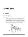
1.3 Product Overview
The purpose of the SpotCell is to enable personal wireless communications in specific
locations within a wireless service area where cell phones do not work, or work poorly,
for example inside a building, or at the cell boundary.
Spotwave Wireless Inc.
1
INTRODUCTION
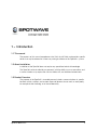
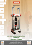
The SpotCell system receives signals from one or more wireless base stations and retransmits the signal to areas where cell phones do not work or work poorly due to
obstructions or the remoteness of the location.
Figure 1.1: Base station signal does not reach wireless subscribers
Figure 1.2: SpotCell improves wireless communications
2
SpotCell® 200 Series
INTRODUCTION
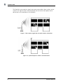
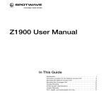
1.4 The SpotCell 200 series
The SpotCell 200 series is able to connect two Coverage Units (CUs) to one Donor Unit
(DU), providing a more cost effective solution for coverage areas up to 50,000 square
feet.
Figure 1.3: SpotCell 200 series dual CU deployment
The SpotCell 200 series retains all the benefits of the existing SpotCell family of adaptive
coverage systems and can be used to easily expand existing installations.
SpotCell® 200 Series
3
INTRODUCTION
4
SpotCell® 200 Series
2 – Getting Started
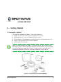
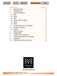
2.1 Packing list - SpotCell
The SpotCell is shipped in two boxes. The first box containing:
Donor Unit (DU) - this is the outward facing part of the system.
Coverage Unit (CU) - this is the indoor part of the system.
Power Adapter - to be plugged into an electrical outlet, and connected to the CU.
Cable - used to connect the CU and DU together.
Mounting Kit which includes:
Note: Parts are provided for the majority of installation options, but do not cover all
possibilities. You may need to purchase additional hardware specific to your mounting
environment before you begin the installation. A tripod and mast would be typical
additional equipment purchased for mounting the SpotCell DU on a rooftop.
DU
CU
Cable
Power
Adapter
Figure 2.1: Components of the SpotCell package
Spotwave Wireless Inc.
5
GETTING STARTED
2.2 Auxiliary CU kit
The SpotCell Auxiliary CU is shipped in a single box containing:
Coverage Unit (CU)
Power Adapter
Intelligent Hub
10 metre cable - connects hub to DU
2, 25 meters cables - used to connect hub to CUs
QuickStart Card
mounting hardware
CU
hub
Figure 2.2: Auxiliary CU kit
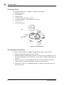
2.3 Unpacking and inspecting
Physically inspect the box for shipping damage before unpacking the SpotCell.
1. Remove the SpotCell components from the box.
2. Remove all packing material from the Donor Unit (DU) and the Coverage Units (CUs).
Save the packaging in case the SpotCell is ever stored or shipped to SpotWave for
service.
3. Check the contents of the package to make sure you have received everything
ordered and verify that the mounting kit contains all the listed parts.
4. Check the DU and CUs for shipping damage. Pay particular attention to the unit’s
outer shell casing.
6
SpotCell® 200 Series
3 – Installation
3.1 Preparing for installation
The following are general considerations and preparations that should be looked at
before installing the SpotCell.
3.1.1 Signal Strength
The SpotCell system brings signals from an area of adequate coverage to an area with
poor or non-existent coverage. It is the DU which captures a good signal, and the CU
that provides the signal to the area with poor cell phone coverage.
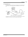
For greater in-building coverage, an Auxiliary CU kit can also be purchased which allows
two CUs to be connected to one DU.
The DU can be mounted inside or outside, as long as it is in an area where your cell
phone works. Generally, the better your cell phone works at the location the DU is
mounted, the better the system will perform.
Figure 3.1: Installation with extra CU for greater coverage
Spotwave Wireless Inc.
9
INSTALLATION
3.1.2 DU Height
In fringe areas, locating the DU as high as possible will provide optimal performance.
3.1.3 Avoid obstructions
General placement of the DU and CU must be in unobstructed areas. For example, the
CU should not be placed on a wall behind any type of furniture (behind items such as
metal filing cabinets would be a particularly poor location). Similarly for the DU, the front
of the unit should not be directly facing any type of metal structures, which are often
found on building rooftops.
3.1.4 Proximity to power source
The indoor unit must be located within 20 feet of a power source.
3.1.5 Distance between DU and CU
Although you should separate the DU and CU as much as possible, there are only 25
meters of cabling provided to connect the two units. Make sure the general location of
the two units is within 25 meters.
Note: An additional cable extension, made from copper core RG6 quad shield cable,
may be inserted, to a maximum of 50 meters total length.
3.1.6 Orientation of DU relative to CU
If possible face the DU and CU in opposite directions, and back to back while
maintaining maximum separation. While not a requirement, some installations will
perform better if the units are positioned in this manner.
3.1.7 Barrier between DU and CU
The greater the physical obstruction between the DU and CU, the better the
performance. Dense obstructions such as brick, concrete or metal walls are better than
wooden or plaster walls.
3.2 Positioning the SpotCell DU (outward facing unit)
It may not be possible to install the DU indoors when installing the SpotCell in remote
areas. An effort should be made to install the DU outdoors and the DU should be
installed as high as possible when the installation is in a remote area,
10
SpotCell® 200 Series
INSTALLATION
3.2.1 Installing the DU
Three methods of positioning the DU (based on location) are outlined in the following
procedure. Specifically they refer to installing inside buildings, on external walls, and on
rooftops.
1. Position the DU (but do not mount it) as close to the final desired mounting location
as possible. The CU does not have to be in its final location while positioning the DU
and it is helpful to have the CU (Main CU for a double coverage installation) near the
DU.
Indoors
Roof
While not strictly
required, it is highly
recommended the DU
be installed facing a
window when installed
indoors.
External wall
The CU does not have to be in its
final position at this time, but it
should not be brought outdoors.
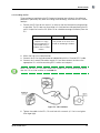
2. Mount the hub in an indoor location.
3. Connect the DU to the hub connector labelled DU with the 10 meter RG11 cable.
4. Connect the 2 meter RG6 cables to each CU and then connect the hub to the
appropriate CUs with the remaining RG11 cables and adapters.
Note: If one of the CUs is an older model with stripped wires for connecting the power,
then this CU must be installed as the MAIN CU.
Figure 3.2: CU installation
5. Tighten the cables to the DU, CUs and hub with a wrench (a 1/4 of a turn tighter
than finger tight).
SpotCell® 200 Series
11
INSTALLATION
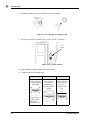
6. Connect the power supply to MAIN CU as shown below.
Figure 3.3: Connecting power supply to CU
7. Ensure the switch on the MAIN CU is in the ‘Install’ (1) position.
CU
switch
Figure 3.4: CU switch location
8. Plug the power supply adapter into a wall socket.
9. To align, hold the DU upright and:
Indoors
Roof
External wall
Rotate the face of
the DU from left
to right in front of
the window.
Rotate it in a full
circle. A time of
10 seconds is
appropriate to
fully complete the
rotation.
Rotate the face of
the unit from left
to right within the
constraints
allowed by the
wall.
wall
window
If not in front of a
window, rotate
the DU in a
complete circle.
12
SpotCell® 200 Series
INSTALLATION
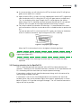
10. As you are rotating, you will notice that the LED on the back of the DU will light up
green, red or amber; this is normal.
11. Again, rotate the DU as in step 6, this time stopping each time the LED is green and
note the direction the DU is facing (the LED may turn green once or multiple times).
This is an indication of the signal strength the DU is receiving from the wireless
phone tower. The DU should be mounted facing the direction the DU was pointed
when the LED was green for the longest period of time during its rotation.
12. For inside installation and exterior wall mountings, it is recommended that various
walls and locations within the structure be tested as suitable locations to position the
DU.
For each location the DU is tested and the LED is green, the display on the bottom
of the CU indicates the relative signal strength that the DU is receiving.
Figure 3.5: Displayed signal strength
Mount the DU in the location that has the highest indicated signal level.
Note: On the upper floors of tall buildings, it may be necessary to tilt the DU down to get
a good signal (green LED).
13. Proceed to page 19 for mounting instructions once the DU location has been
optimized.
3.3 Choosing a location for the SpotCell CU
The CU should be optimized and mounted, after the DU has been optimized and
mounted. Generally, the CU should be mounted in a location as far as possible from the
DU, while being within the area where you require improved coverage.
If mounted on a ceiling, the unit should be downward facing, and in the center of the
area requiring cell phone coverage.
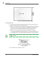
If mounted on a wall, the unit should be positioned in the middle of the area to be
covered side-to-side, and off-centered slightly front-to-back, approximately as shown
below in Figure 3.6:“CU position and signal coverage”. The unit should be mounted as
high on the wall as possible.
SpotCell® 200 Series
13
INSTALLATION
Figure 3.6: CU position and signal coverage
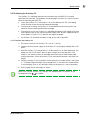
3.3.1 Positioning the CU
1. Ensure that the DU position has been optimized and has been mounted in place.
2. Move the switch on the CU from ‘Install’ to ‘Active’.
3. Hold the CU in the position it is to be mounted. In an ideal application, the display on
the CU will show 5 bars of signal strength and coverage area. If the display is not
showing 5 bars for coverage area and there are alternate possible mounting
locations, move the CU to the alternate locations and check the display.
4. Place the CU in the location showing maximum number of bars (see Figure
3.7:“Displayed Signal Strength and Coverage Area”). In the event the number of bars
is not changing, which is very possible, choose a location that is most convenient.
Note: Each time the CU is moved, wait approximately 25 seconds for the coverage area
bars (
) to stabilize.
Figure 3.7: Displayed Signal Strength
and Coverage Area
5. Refer to page 19 for mounting instructions.
14
SpotCell® 200 Series
INSTALLATION
3.4 Positioning the Auxiliary CU
The Auxiliary CU should be optimized and mounted after the MAIN CU has been
optimized and mounted. The guidelines for positioning the Auxiliary CU are the same as
those for mounting the MAIN CU.
mount the Auxiliary CU in a location as far as possible from the DU, while being
within the area where you require improved coverage.
if mounted on a ceiling, the Auxiliary CU should be downward facing, and in the
center of the area requiring cell phone coverage.
if mounted on a wall, the Auxiliary CU should be positioned in the middle of the area
to be covered side-to-side, and off-centered slightly front-to-back, approximately as
shown below in Figure 3.6:“CU position and signal coverage”.
the Auxiliary CU should be mounted as high on the wall as possible.
3.4.1 To position the Auxiliary CU
1. Ensure the switch on the Auxiliary CU is set to ‘2’ (active).
2. Connect the extra power supply to the Auxiliary CU and plug the adapter into an AC
outlet.
3. Hold the Auxiliary CU in the position it is to be mounted. In an ideal application, the
display on the CU will show 5 bars of signal strength and coverage area. If the
display is not showing 5 bars for coverage area and there are alternate possible
mounting locations, move the Auxiliary CU to the alternate locations and check the
display.
4. Place the Auxiliary CU in the location showing maximum number of bars (see Figure
3.7:“Displayed Signal Strength and Coverage Area”). In the event the number of bars
is not changing, which is very possible, choose a location that is most convenient.
5. Refer to page 24 for mounting instructions.
Note: Each time the Auxiliary CU is moved, wait approximately 25 seconds for the
coverage area bars (
) to stabilize.
SpotCell® 200 Series
15
INSTALLATION
3.5 Auxiliary Antenna
The SpotCell Coverage Extension kit (purchased separately) can extend coverage into
hard to reach places that are blocked by obstructions such as dense walls or shadowed
by elevator shafts or ductwork.
Auxiliary
antenna
connection
Figure 3.8: Auxiliary antenna connection on CU
Instructions for connecting and mounting the auxiliary antenna are included in the
Coverage Extension kit.
16
SpotCell® 200 Series
4 – Mounting
All necessary hardware required for mounting on internal/external walls, or
pipes is included in the mounting kit.
4.1 Running the cable through a wall
If it is necessary to run a cable through a wall, use a masonry or wood drill bit
to drill a 5/8-inch diameter hole.
After passing the cable through, use the putty in the installation kit to fill the
hole around the cable.
4.2 Mounting the DU
The DU may be indoor or outdoor mounted. Based on the direction the DU will
point, consider possible mounting locations.
The illustrations on the following pages show some of the possible mounting
options.
Note: Mount the angle bracket on the flanged side of the mounting bracket and
use the two mounting holes if no horizontal movement is required.
Spotwave Wireless Inc.
19
MOUNTING
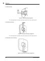
4.2.1 Wall mounting
Figure 4.1: Wall mounting arrangement
This mounting allows for rotation and some upward tilt but mainly downward tilt.
4.2.2 Overhead mounting
Figure 4.2: Overhead mounting arrangement
This mounting allows for rotation and some upward tilt but mainly downward tilt.
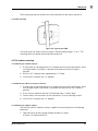
4.2.3 Horizontal surface mounting
Figure 4.3: Horizontal mounting arrangements
20
SpotCell® 200 Series
MOUNTING
These mountings allow for rotation and some downward tilt but mainly upward tilt.
4.2.4 Pipe mounting
Figure 4.4: Pipe mounted DU
Use hose clamps to mount the unit to a pipe. The hose clamp range is 2" to 5". This
mounting allows for rotation and limited up and down tilt.
4.3 DU outdoor mounting
4.3.1 Mounting to a wood structure
1. Use the holes in mounting bracket as a template and mark the hole locations. Mark
two regular holes if no motion is required or the hole and the slot if motion is
required.
2. Drill two .125" diameter holes approximately. 2.5" deep.
3. Install the DU using the two 1/4" lag bolts.
4.3.2 Mounting to a brick or concrete structure:
1. Use the holes in mounting bracket as a template and mark the hole locations. Mark
the two regular holes if no motion is required or the hole and the slot if motion is
required.
2. Use a masonry drill bit to drill two 5/16"diameter holes, 2 inches deep.
3. Insert masonry screw anchors so that the anchor is flush to mounting surface.
4. Install the DU using the two 1/4" lag bolts.
4.3.3 Mounting to a pipe or tubing:
Use the two stainless steel hose clamps supplied in the mounting kit for the following
procedure.
1. Feed the end of the hose clamp through the holes as shown
in Figure 4.4:“Pipe mounted DU”.
SpotCell® 200 Series
21
MOUNTING
2. Rotate the unit to point the unit to the signal source and tighten clamps.
Note: DO NOT use cable ties to mount the DU.
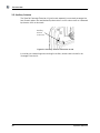
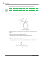
4.3.4 Attaching the cable
While securing the cable, ensure that a drip loop is fashioned near the DU (to prevent
water from collecting around the cable where it attaches to the DU) and secured in place
as shown in Figure 4.5:“Drip loop” below.
Figure 4.5: Drip loop
Fashion the drip loop and fasten a black tie wrap around the loop to keep the loop
fastened.
To attach the cable to an existing pipe or cable run:
Use tie-wraps to attach the cable to an existing pipe or cable run.
To attach the cable to wood or siding:
Secure the cable to the wall using a cable loop strap as shown below. Mount the
loop strap directly to the wall where possible using a #6 x 1.5” wood screw.
Figure 4.6: Cable strap
22
SpotCell® 200 Series
MOUNTING
To attach the cable to a brick or concrete wall:
1. Drill a 3/16 diameter x 1 1/4 inch deep hole using a masonry drill bit.
2. Insert the anchor flush with the mounting surface.
3. Use cable clamps and screws to attach cable to the wall.
4.3.5 Bringing the cable indoors
To bring the cable indoors, it may be necessary to drill a hole through the wall.
To bring the cable through an exterior wall:
1. Depending on the material the wall is made of use a wood or masonry drill bit to drill
a 5/8 inch diameter hole.
2. Pass the connector and cable through the wall.
3. Use the putty/sealant provided to fill the hole.
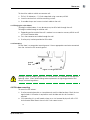
4.3.6 Grounding:
Ensure there is a connection to earth ground. Use an appropriate conductor connected
from the stud on the DU to earth ground.
ground
stud
Figure 4.7: DU ground stud
Warning! Failure to properly ground the DU will leave the unit vulnerable to damage from
lightning strikes. Check local building code requirements for lightning protection and
comply with local regulations.
4.4 DU indoor mounting
To mount the DU indoors:
1. Use the mounting bracket as a template and mark the hole locations. Mark the two
regular holes if no motion is required or mark the hole and the slot if motion is
required.
2. If the mounting is in a solid wood surface, or a stud covered by drywall, drill a 5/32
inch diameter hole. Mount the unit with 2 inch wood screws.
or
SpotCell® 200 Series
23
MOUNTING
If the mounting is in drywall, drill a ¼ diameter hole and insert an anchor. Mount the
unit with 1/2 inch pan head screws.
3. Attach cables to the wall using tie wraps and mount directly to the wall where
possible (using 1/2 inch pan head screws). If an anchor is required drill a 3/16 inch
diameter hole, insert the anchor, and fasten with 1/2 inch pan head screws.
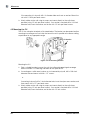
4.5 Mounting the CU
The CU has a bracket attached as illustrated below. The bracket can be rotated to allow
mounting to a ceiling or wall such that the face of the unit is parallel to the floor or ceiling,
or positioned at any appropriate angle.
CU bracket
Figure 4.8: CU mounting bracket.
Mounting the CU
1. Find a suitable location to mount the unit that will provide good signal coverage.
Refer to section 3.3“Choosing a location for the SpotCell CU”.
2. If mounting on a solid wood surface, or stud covered by drywall, drill a 1/8th inch
diameter hole and mount with #6 x 1.5” screws.
or
If mounting in drywall, drill a ¼ inch diameter hole, insert the nylon screw anchor, and
then mount with a 1/2” pan head screw.
3. Attach cables to the wall using tie wraps and mount directly to the wall where
possible (using 1/2 inch pan head screws). If an anchor is required drill a 3/16 inch
diameter hole, insert the anchor, and fasten with 1/2 inch screws.
24
SpotCell® 200 Series
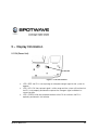
5 – Display Information
5.1 DU (Donor Unit)
DU LED
Figure 5.1: DU LED location
LED is RED: the DU is not capturing an adequate enough signal for the system to
operate.
LED is YELLOW: the captured signal is within range and the system will function, but
the DU is not properly positioned to capture the strongest signal available in its
current location.
LED is GREEN: after one complete rotation of the DU this indicates the DU is
optimally positioned in this location.
Spotwave Wireless Inc.
27
DISPLAY INFORMATION
5.2 CU
5.2.1 LED
The CU LED indicates three conditions:
OFF = no DC power supply present
RED = power present + system alarm condition
GREEN = power present + no alarm condition
CU
LED
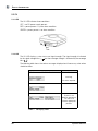
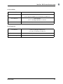
5.2.2 LCD
The CU LCD displays system status and signal strength. The signal strength is indicated
by the signal strength bars (
) and the coverage strength is indicated by the coverage
bars (
).
The following table shows the various messages displayed and if necessary, what action
should be taken.
Display with alternating display (if present)
Action (if required)
Initializing.
No action required.
System is not
optimally positioned.
Turn the DU to
another appropriate
position.
Table 1: CU Display States
28
SpotCell® 200 Series
DISPLAY INFORMATION
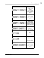
Display with alternating display (if present)
Action (if required)
System will not
function.
Turn the DU to
another appropriate
position.
Turn the DU to
another appropriate
position.
Check the RF cable
and verify that it is
connected properly.
Make sure the length
of the RF cable is less
than 75 meters.
Call product support.
Telephone #:
1-877-610-9586
All OK.
No action required.
Signal weak, but
working.
No action required.
Turn the DU to
another appropriate
position.
Table 1: CU Display States
SpotCell® 200 Series
29
DISPLAY INFORMATION
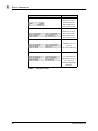
Display with alternating display (if present)
Action (if required)
Move the CU to an
alternate location,
preferable farther
away from the DU.
Move the CU to an
alternate location,
preferable farther
away from the DU.
Temporary loss of
service.
No action required
Loss of service for
more than 24 hours.
Turn the DU to
another appropriate
position.
Table 1: CU Display States
30
SpotCell® 200 Series
6 – Trouble Shooting Information
1. Status: The display on the bottom of the CU dynamically displays information
regarding the SpotCell system and environment during installation and operation.
Action: Look at the information display to determine if the SpotCell system is
indicating a fault.
2. Status: The LED on the DU is not illuminating during the installation.
Action: Ensure the following:
The provided cable is connected to the CU and DU.
The power supply is connected to the CU.
The power supply is plugged into an electrical outlet.
The switch on the back of the CU is in the ‘Install’ position.
If the LED is still not illuminating, contact technical support.
3. Status: My cell phone does not work around the location I would like to install the
SpotCell DU.
Action: Try positioning the DU externally as high as possible.
4. Status: While optimizing the DU for installation, you found that the LED turned green
in multiple locations, indicating each had adequate signal strength. How do you
determine which location is optimal for the DU?
Action: Look at the signal level indicated on the display on the bottom of the CU
each time the green light appears on the DU during alignment. Mount the DU in the
location as indicated having the highest signal level. Figure 6.1:“Displayed signal
strength.” below shows an example of the signal strength display.
Spotwave Wireless Inc.
31
TROUBLE SHOOTING INFORMATION
Figure 6.1: Displayed signal strength.
5. Status: The DU and CU are installed properly, but your cell phone only works in close
proximity to the CU.
Action: There are three factors that may be affecting coverage as described below:
Visually inspect the area around the CU. Ensure that there are not any large
metallic objects directly between the CU and the area where cell phone coverage
is not adequate. Remount the CU so that it is out in the open.
If the signal the DU is receiving is very weak (although still strong enough to allow
operation), the area around the CU within which a cell phone can function will be
relatively small. An effort can be made to improve system performance by raising
or otherwise repositioning the DU in an effort to obtain a stronger signal. In Install
mode, signal strength is shown on the CU display.
Check with your vendor that your SpotCell product is compatible with your cell
phone service.
6. Status: The coverage area around the CU suddenly shrinks after a long period of
reliable operation.
Action: This is most likely due to man made environmental influences such as a large
building being erected somewhere in between the DU and the location the DU is
receiving a signal from. Repeating the install procedure with the DU in its current
position may improve system performance (i.e. Putting the CU switch into ‘Install’
and spinning the DU around twice, aligning it in the direction indicated by the green
LED on the second spin.). If this does not help, the DU may have to be physically
repositioned at a different location; going through the install procedure starting at
page 9 is necessary at this point.
7. Status: The Auxiliary CU of a SpotCell 211 will not function properly after the
breaking and re-establishing of the cable connection.
Action: If the cable connection between the AUX CU and the SpotCell 211 hub is
broken, then the AUX CU must be re-set manually (after the cable connection has
been re-established) by powering the CU off and then back on.
32
SpotCell® 200 Series
TROUBLE SHOOTING INFORMATION
8. Information: Remote installation SpotCell characteristics.
In order for the SpotCell system to function, there are two basic parameters that
must be met. The DU must receive a minimum amount of wireless signal, and a
physical environment that blocks wireless signals must be in between the DU and
CU (i.e. a wall).
If the DU is not receiving an adequate signal, the system will not work, or, it will work
but provide a very limited area around the CU in which a cell phone will function. In
this instance, it may be possible that only one cell phone will be capable of using the
system at a time. This is typical of applications that are on the fringe, or outside of a
wireless providers advertised coverage area. Improved performance will typically
only be attained by moving the DU to a higher location.
9. Information: Residential (or building) installations that do not provide for brick,
concrete, metal, or other dense material between the DU and CU.
Action: In this situation it is possible that the signal emitted by the DU will be received
by the CU. This will result in the system lowering the power of the signal it is emitting;
and therefore the area around the CU in which a cell phone will function will become
smaller. To improve performance in this scenario, it is important to:
Maximize the height of the DU
Separate the DU and CU horizontally as much as possible
Mount the DU and CU in a back-to-back manner.
It is recommended to use 50 meters of cable in between the DU and CU if
possible in an effort to vertically and horizontally separate the system units.
10. Information: Proper alignment rotation
Action: Make sure the DU is rotated once completely within the area available for
rotation, and then move through the same rotation again. DU alignment is based on
optimizing the direction the DU is facing after initially establishing the range of signal
available by rotating the DU in a circle. Once the DU has been rotated in a circle and
established the level of signal available, it now sets a threshold based on the
surroundings to determine when the LED will illuminate green. If the DU is not
pointing in a direction that is within a certain range of the highest signal it
encountered since being in ‘Install’ mode, the LED will not turn green. Additionally,
the LED will not illuminate green if a minimum signal level is not achieved during the
initial rotation.
SpotCell® 200 Series
33
TROUBLE SHOOTING INFORMATION
34
SpotCell® 200 Series
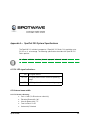
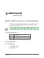
Appendix A – SpotCell 200 System Specifications
The SpotCell 200 solution incorporates 2 SpotCell 100 Series CUs providing up to
50,000 sq. ft. of coverage. The following specification describes the SpotCell 100
Series product.
Note: Spotwave Wireless has the right to change specifications without notice.
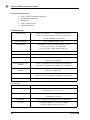
A.1 DU LED signal indications:
RED
BS signal too low
YELLOW
BS signal present and at minimum operating
range
GREEN
BS signal is within normal operating range
A.2 Antenna beam width:
A.2.1 CU Antenna Summary
SpotCell® 200
Gain +3 dBi (10 dB maximum directivity)
Elevation Beamwidth 180°
Azimuth Beamwidth 175°
Front-to-Back 12 dB
Horizontally Polarized
35
SPOTCELL 200 SYSTEM SPECIFICATIONS
A.2.2 DU Antenna Summary
Gain 10 dBi (10 maximum directivity)
Elevation Beamwidth 62°
Azimuth 50°
Front-to-Back 20 dB
Vertically Polarized
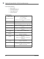
A.3 Architecture
Frequency Band
Uplink: 824-849 MHz
Downlink: 869-894 MHz
Complete A or B sub-bands factory set (adjacent carrier rejection)
* Must be specified at time of order
Formats Supported
AMPS, NAMPS, CDMA, TDMA
Coverage Area
Fully adaptive, supports multiple simultaneous users
Up to 20,000 Sq feet (~1850 Sq Meters)
or 50,000 Sq feet in open unobstructed areas
System Gain
Automatic, fully adaptive, Maximum 93dB downlink, 89 dB uplink
RF Environment
Up to 147dB path loss to/from the base station
Input Overload Protection
Uplink: Fully adaptive
Downlink: Fully adaptive
Maximum Output Levels
(radiated)
Uplink: Fully adaptive, up to +30 dBm EIRP (composite)
Third Order Intercept
(radiated)
Uplink: +52 dBm EIRP
Downlink: Fully adaptive up to +9 dBm EIRP (composite)
Downlink: +30 dBm EIRP
Power Supply
7.5 VDC/ 10.25 VDC universal power adapter that connects to the
indoor unit, Donor Unit power is supplied via the RF cable
Power Consumption
< 22 W
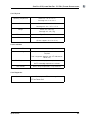
A.3.1 Physical
Operating Temperature
Size
Donor unit: -40° to +55° C
Coverage unit: 0° to +40° C
Donor unit: 15"w 12" h 4" d
Coverage unit: 9"w 7.25" h 2.5" d
Weight
Donor unit: 4 lb (2 kg)
Coverage unit: 2 lb (1 kg)
RF Connectors
Type F, outdoor unit supplied with weather proof boot
RF Cable
RG6 Quad shielded 82’ or 25 meters supplied
(System supports up to 164 ft. or 50 m)
36
SpotCell® 200
SPOTCELL 200 SYSTEM SPECIFICATIONS
A.3.2 Installation
Installation Time
Less than one hour typical
Outdoor Unit Alignment
No prior knowledge of base station location required
Built in alignment algorithm (LED Indicator on outdoor unit)
Test Equipment
None required
No RF knowledge required for installation
User Controls
None, setup and operation is fully automatic
A.3.3 Diagnostics
Fault Indicators
LED on DU (during installation only)
LCD and LED indicator on indoor unit
Remote Connectivity
Serial data port on indoor unit
System Interrogation
LCD indicator on indoor unit
SpotCell® 200
37
SPOTCELL 200 SYSTEM SPECIFICATIONS
38
SpotCell® 200
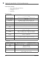
Appendix B – SpotCell 211 (using SpotCell 111 CUs) System Specifications
The SpotCell 211 solution incorporates 2 SpotCell 111 CUs, providing up to 50,000
sq. ft. of coverage. The following specification describes the SpotCell 111 product.
Specifications for the SpotCell.
Note: Spotwave Wireless has the right to change specifications without notice.
B.1 DU LED signal indications:
RED
YELLOW
BS signal too low
BS signal present and within range
GREEN
BS signal is at maximum
B.2 Antenna beam width:
B.2.1 CU Antenna Summary
SpotCell® 211
Gain +3 dBi
Azimuth Beamwidth 145°
Front-to-back 15 dB
Elevation 160°
39
SPOTCELL 211 (USING SPOTCELL 111 CUS) SYSTEM SPECIFICATIONS
B.2.2 DU Antenna Summary
Gain 12 dBi (13 dB nominal directivity)
Elevation Beamwidth 36°
F/B 26 dB
Azimuth 46°
B.3 Architecture
Frequency Band
Full A, D, B, E, F, C band and sub-band (C1, C2, C3, C4, C5) selectivity
5, 7.5, 10, 15, 20 MHz
Passband Bandwidth
*Start/stop receive band frequency must be specified at time of order.
Formats Supported
GSM/TDMA
Coverage Area
Fully adaptive, supports multiple simultaneous users
Up to 20,000 Sq feet (50,000 sq.ft. in open areas)
System Gain Uplink
Automatic, fully adaptive, Maximum 81 dB (including antennas)
System Gain Downlink
Automatic, fully adaptive, maximum 92dB (including antennas)
Downlink Operating
Range
-106 to –44 dBm (Rx Isotropic Power)
Input Overload
Protection
Uplink: Fully adaptive
Maximum Output Levels
(radiated)
Third Order Intercept
(radiated)
Downlink: Fully adaptive
Uplink: Fully adaptive, up to +30 dBm EIRP (Composite)
Downlink: Fully adaptive up to +7 dBm EIRP (Composite)
Uplink: +50 dBm EIRP
Downlink: +30 dBm EIRP
Power Supply
7.5 VDC/ 10.25 VDC Universal power adapter that connects to the Indoor
Unit; Donor Unit power is supplied via the RF cable
Power Consumption
< 28 W
B.3.1 Physical
Operating Temperature
Size
Weight
Donor unit: -40° to +55° C
Donor unit: 15"w 12" h 4" d
Coverage unit: 0° to +40° C
Coverage unit: 9"w 7.25" h 2.5" d
Donor unit: 4 lb (2 kg)
Coverage unit: 2 lb (1 kg)
RF Connectors
Type F; weatherproof
RF Cable
RG6 quad-shield 82’ or 25 m supplied
(System supports 164 ft. or 50 m)
40
SpotCell® 211
SPOTCELL 211 (USING SPOTCELL 111 CUS) SYSTEM SPECIFICATIONS
B.3.2 Installation
Installation Time
Less than one hour typical
Outdoor Unit Alignment
No prior knowledge of base station location required
Built in alignment algorithm with LED indicator on Donor Unit)
Test Equipment
No test equipment required
No RF knowledge required for installation
User Controls
None; setup and operation is fully automatic
B.3.3 Diagnostics
System Status
LCD display and LED on Coverage Unit
LED on Donor Unit
SpotCell® 211
41
SPOTCELL 211 (USING SPOTCELL 111 CUS) SYSTEM SPECIFICATIONS
42
SpotCell® 211
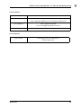
Appendix C – SpotCell 212 (using SpotCell 112 CUs) System Specifications
The SpotCell 212 solution incorporates 2 SpotCell 112 CUs, providing up to 50,000
sq. ft. of coverage. The following specification describes the SpotCell 112 product.
Note: Spotwave Wireless has the right to change specifications without notice.
C.1 DU LED signal indications:
RED
YELLOW
BS signal too low
BS signal present and within range
GREEN
BS signal is at maximum
C.2 Antenna beam width:
C.2.1 CU Antenna Summary
SpotCell® 212
Gain +3 dBi
Elevation Beamwidth 160°
Azimuth Beamwidth 145°
Front-to-Back 15 dB
Horizontally Polarized
43
SPOTCELL 212 (USING SPOTCELL 112 CUS) SYSTEM SPECIFICATIONS
C.2.2 DU Antenna Summary
Gain 11.5 dBi
Elevation Beamwidth 36°
Azimuth Beamwidth 46°
Front-to-Back 25 dB
Vertical Polarization
C.3 Architecture
Frequency Band
Passband Bandwidth
Full A, D, B, E, F, C band and sub-band (C1, C2, C3,
C4, C5) selectivity
5, 7.5, 10, 15, 20 MHz
*Start/stop receive band frequency must be specified at time of
order.
Formats Supported
CDMA
Coverage Area
Fully adaptive, supports multiple simultaneous users
Up to 20,000 Sq feet (50,000 sq.ft. in open areas)
System Gain Uplink
Automatic, fully adaptive, Maximum 81 dB (including
antennas)
System Gain Downlink
Automatic, fully adaptive, maximum 92dB (including
antennas)
Downlink Operating
Range
-106 to –44 dBm (Rx Isotropic Power)
Input Overload
Protection
Uplink: Fully adaptive
Downlink: Fully adaptive
Maximum Output Levels
(radiated)
Uplink: Fully adaptive, up to +30 dBm EIRP
(Composite)
Downlink: Fully adaptive up to +7 dBm EIRP
(Composite)
Third Order Intercept
(radiated)
44
Uplink: +50 dBm EIRP
Downlink: +30 dBm EIRP
Power Supply
7.5 VDC/ 10.25 VDC Universal power adapter that
connects to the Indoor Unit; Donor Unit power is
supplied via the RF cable
Power Consumption
< 28 W
SpotCell® 212
SPOTCELL 212 (USING SPOTCELL 112 CUS) SYSTEM SPECIFICATIONS
C.3.1 Physical
Operating Temperature
Donor unit: -40° to +55° C
Coverage unit: 0° to +40° C
Size
Donor unit: 15"w 12" h 4" d
Coverage unit: 9"w 7.25" h 2.5" d
Weight
Donor unit: 4 lb (2 kg)
Coverage unit: 2 lb (1 kg)
RF Connectors
Type F; weatherproof
RF Cable
RG6 quad-shield 82’ or 25 m supplied
(System supports 164 ft. or 50 m)
C.3.2 Installation
Installation Time
Less than one hour typical
Outdoor Unit Alignment
No prior knowledge of base station location
required
Built in alignment algorithm with LED indicator on
Donor Unit)
Test Equipment
No test equipment required
No RF knowledge required for installation
User Controls
None; setup and operation is fully automatic
C.3.3 Diagnostics
System Status
LCD display and LED on Coverage Unit
LED on Donor Unit
SpotCell® 212
45
SPOTCELL 212 (USING SPOTCELL 112 CUS) SYSTEM SPECIFICATIONS
46
SpotCell® 212
Appendix D – Safety Hints
Customer safety is a concern we would like to address in a sensible and proactive
manner. To this end, the following notes have been provided as a reference to help
installers remain safe and think about safety in all aspects of the installation.
The following notes are to be considered as informational only, and not exhaustive or
complete.
D.1 Lightning
Never attempt to install the DU outdoors while a lightning storm is in progress in your
immediate or neighboring vicinity. The National Lightning Institute says for every five
seconds between the flash of lightning and a thunderclap, the lightning is one mile
away. If lightning is within 3 miles (15 second count between flash and thunder) of your
location, do not attempt an installation.
D.2 Working Aloft
When working aloft, it is best to work in pairs. Avoid attempting procedures alone that
are best carried out with a spotter or by two people.
D.2.1 Power Tools
Proper eye protection should be worn when using a drill or any other type of power
tool.
D.2.2 Working with Ladders
Properly secure your ladder and work in pairs. Make sure the ladder is properly tied off
and use an insulated ladder when working around power lines.
SpotCell 200 Series
47
SAFETY HINTS
D.2.3 Grounding
Ensuring the DU is properly grounded in external installations will help to prevent
property damage and personal injury during lightning storms.
D.3 Overhead Power Lines
While overhead power lines may appear to be insulated, they most likely are not
insulated. Always thoroughly investigate your surroundings prior to installing masts or
the DU in an outdoor location.
Never attempt installation without adequate lighting, as shadows and trees can obscure
power lines.
48
SpotCell 200 Series
www.spotwave.com
Spotwave Wireless Inc. 1 Hines Road, Ottawa ON K2K 3C7 Canada
© 2005 Spotwave Wireless Inc. All rights reserved. Printed in Canada
Spotwave and SpotCell are trademarks of Spotwave Wireless Inc. Patents pending.
780-00003-01-03