1
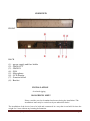
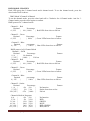
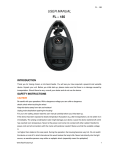
INTELLIGENT LED COLOR SYSTEM FL-672 User Manual www.flash-butrym.pl Page 1 COUTION! keep this device away from rain and moisture! Unplug mains lead before opening the housing! For your own safety, please read this user manual carefully before you initially start-up Every person involved with the installation. operation and maintenance of this device has to Be qualified Follow the instructions of this manual Consider this manual to be part of the total product Keep this manual for the entire service life of the product Pass this manual on to every further owner or user of the product Download the latest version of the user manual from the internet INTRODUCTION Thank you for having chosen FL-672 Intelligent LED color System. If you follow the instructions given in this manual. We are sure that you will enjoy this device for a long time. The FL-672 Intelligent LED Color System features a built-in microphone. Unpack your FL-672 Intelligent LED Color System. Before you initially start-up. Please make sure that three is no damage caused by transportation, Should there be any. Consult your dealer and do not use the device. SAFETY INSTRUCTION CAUTION! Be careful with your operations. With a dangerous voltage you can suffer a dangerous electric shock hen touching the wires! This device has left our premises in absolutely perfect condition. In order to maintain this condition and to ensure a safe operation. It is absolutely necessary for the user to follow the safety instructions and warning notes written in this user manual Important: Damages caused by the disregard of this user manual are not subject to warranty. The dealer will not accept liability for any resulting defects or problems. If the device has been exposed to drastic temperature fluctuation (e.g. after transportation) do not switch it on immediately. The arising condensation water might damage your device. Leave the device switched off until it has reached room temperature. Please make sure that there are no obvious transport damage. Should you notice any damages on the A/C connection cable or on the casing. Do not take the device into operation and immediately consult your local dealer This device falls under protection-class 1.The power plug must only be plugged into a protection class 1 outlet. The voltage abd frequency must exactly be the same as stated on the device, Wrong voltage or power outlet can lead to the destruction of the device and to mortal electrical shock. www.flash-butrym.pl Page 2 Always plug in the power plug last. The power plug must always be inserted without force. Make sure that the plug is tightly connected with the outlet. Never let the power-cord come into contact with other cables! Handle the power-cord and all connections with the mains with particular caution! Never touch them with wet hands. As this could lead to mortal electrical shock. Never modify. Bend strain mechanically put pressure on pull or heat up the power cord. Never operate next to sources of heat or cold, Disregard can lead to power cord damages fire or mortal electrical shock. The cable insert or the female part in the device must never be strained. There must always be sufficient cable to the device. Otherwise the cable may be damage which may lead to mortal damage. Make sure that the power-cord is never crimped or damage by sharp edged. Check the device and the power-cord from time to time. If extension cords are used, make sure that the core diameter is sufficient for the required power consumption of the device. All warning concerning the power cord are also valid for possible extension cords. Always disconnect from the mains, when the device is not in use or before cleaning it. Only handle the power-cord by the plug. Never pull out the plug by tugging the power-cord. Otherwise the cable or plug can be damage leading to mortal electrical shock. If the power switch is not accessible. The device must be disconnected via the mains. If the power plug or the device is dusty, the device must be taken out of operation, disconnected and then be cleaned with a dry cloth. Dust can reduce the insulation which may lead to mortal electrical shock. More severe dirt in and at the device should only be remove by a specialist. There must never be any object entering into the device. This is especially valid for metal parts. If any metal parts like staples or coarse metal chips enter into the device, the device must be taken out of operation and disconnected immediately. Malfunction or short-circuits caused by metal part may cause mortal injuries During the initial start-up some smoke or smell may arise. This is a normal process and does not necessarily mean that the device is defective. HEALTH HAZARD! Never look directly into the light source, as sensitive persons may suffer an epileptic shock (especially meant for epileptics)! Keep away children and amateurs! Never leave this device running unattended OPERATING DETERMINATIONS This device is a lighting effect for creating decorative effects, This product is allowed to be operated with 110v and 220v. 47-64Hz and was designed for indoor use only. This device is designed for professional use. e.g. On stages, in discotheques, theatres etc. www.flash-butrym.pl Page 3 Lighting effects are not designed for permanent operation. Consistent operation breaks will ensure that the device will serve you for a long time without defects. Do not shake the device, Avoid brute force when installing or operating the device. When choosing the installation -spot, please make sure that the device is not exposed to extreme heat, moisture or dust. There should not be any cables lying around. You endanger your own and the safety of others! This device must never be operated or stockpiled in surrounding where splash water. Rain, moisture or fog may harm the device. Moisture or very high humidity can reduce the insulation and lead to mortal electrical shocks. When using smoke machines, make sure that the device is never exposed to the direct smoke jet and is installed in a distance of 0.5 meters between smoke machine and device. The room must only be saturated with an amount of smoke that the visibility will always be more than 10 meters. The ambient temperature must always be between -5* c and +45* c keep away from direct insulation (particularly in car) and heaters. The relative humidity must not exceed 50% with an ambient temperature of 45* c This devise must only be operated in an altitude between -20 and 2000 m over NN. Never use the device during thunderstorms. Over voltage could destroy the device. Always disconnect the device during thunderstorms. This device is only allowed for an installation via the mounting bracket. In order to safeguard sufficient ventilation leave 50 cm of tree space around the device. The housing must never touch surrounding surfaces or objects. Make sure that the area below the installation place is blocked when rigging, dragging or servicing the fixture. Always fix the fixture with an appropriate safety-rope. The maximum ambient temperature t a =45* c must never be exceeded. Operate the device only after having familiarized with its function. Do not permit operation by persons not qualified for operating the device. Most damages are the result of unprofessional operation! Never use solvents or aggressive detergents in order to clean the device! Rather use a soft and damp cloth. Please use the original packaging if the device is to be transported. Please consider that unauthorized modifications on the device are forbidden due to safety reasons! Never remove the serial barcode from the device as this would make the guarantee void. If this device will be operated in any way different to the one described in this manual, the product may suffer damage and the guarantee becomes void. Furthermore, any other operation may lead to dangers like short-circuit. Bums, electric shock, lamp explosion, crash etc. www.flash-butrym.pl Page 4 OVERVIEW FRONT BACK (1) – power supply and fuse holder (2) – DMX OUT (3) – DMX IN (4) – FAN (5) – Microphone (6) – LCD Display (7) – Function wheel (8) - Bracket INSTALLATION Overhead rigging DANGER TO LIFE! Please consider your local standard and norms during the installation! The installation! must only be carried out by an authorized dealer! The installation of the device has to be built and constructed in a way that it can hold 10 times the weight for 1 hour without any harming deformation. www.flash-butrym.pl Page 5 The installation must always be secured with a secondary safety attachment. e.g. An appropriate catch net. This secondary safety attachment must be constructed in a way no part of the installation can fall down if the main attachment fails. When rigging, dragging or servicing the device staying in the area below the installation place, on bridges, under high working places and other endangered area is forbidden. The operator has to make sure that safety-relating and machine-technical installations are approved by an expert before taking into operation for the first time and after changes before taking into operation another time. The operator has to make sure that safety-relating and machine-technical installation are approved by an expert after every four year in the course of an acceptance test. The operator has to make sure that safety-relating and machine-technical installation are approved by a skilled person once a year. PROCEDURE The device should be installed outside area where persons may walk by or be seated. IMPORTANT! OVERHEAD RIGGING REQUIRES EXTENSIVE EXPERIENCE, including (but not limited to calculating working load limits) installation material being used, and periodic safety inspection of all installation material and the device. If you lack these qualification, do not attempt the installation yourself, but instead use a professional structural rigger. Improper installation can result in bodily and or damage to property. The device has to be installed out of the reach of people. If the device shall be lowered from the ceiling or high joists, professional trussing systems have to be used. The device must never be fixed swinging freely in the room. COUTION! Devices in hanging installation may cause severe injuries when crashing down! If you have doubts concerning the safety of a possible installation, do not install the device! Before rigging make sure that the installation area can hold a minimum point load of 10 times the device’s weight. DANGER OF FIRE! When installing the device, make sure there is no highly-inflammable material (decoration articles, etc.) within a distance of min. 0.5 meter Mount the device to your trussing system using an appropriate clamp. For overhead use, always install a safety-rope that can hold at least 12 times the weight of the fixture. You must only use safety-rope with quick link with screw cap. Pull the safety-rope through the attachment eyelet and over the trussing system or a safe fixation spot. Insert the end in the quick link and tighten the safety screw. www.flash-butrym.pl Page 6 The maximum drop distance must never exceed 20 cm. A safety rope which already hold the strain of a crash or which is defective must not be used again. Adjust the desired inclination-angle via the mounting-bracket and tighten the fixation screws. Connect the fixture to the mains with the power-plug. The occupation of the connection-cables is as follow: Cable pin international Brown live L Blue Neutral N Yellow/Green Earth O The earth has to be connected! If the device will be directly connected with the local power supply network, a disconnection switch with a minimum opening of 3mm at every pole has to be included in the permanent electrical installation. Lighting effects must not be connected to dimming-pack DANGER TO LIFE! Before taking into operation for the first time, the installation has to be approved by an expect! OPERATION Initialization After you connected the effect to the mains, the FL-672 Intelligent LED Color system starts running, the LCD will display FLASH FL-672 while the fixture in initializing. After initialization, the LCD will display ''Addr ****when there is DMX connection (***indicates the present DMX address) But when there is no DMX connection. Instead. It will display the preset non-DMX running mode: Auto. Sound, or Manual. LCD MENU SEQUENCE Roll the wheel by the LCD clockwise, it will show menu options in the following sequence: Addr*** Manual Blue ***manual Green *** Manual Red ***No Dmx Auto/Sound. Manual, Case 8 ***/** Chase 8 ***/**Chase 7 ***/** Chase 7***/** Chase 6 ***/** Chase 6***/** Chase 5 ***/** Chase 5 ***/** Chase 4 ***/** Chase 4 ***/** Chase 3 ***/** Chase 3 ***/** Chase 2 ***/** Chase 2 ***/** Chase 1**/** Chase 1 ***/**, DMX Mode 8-Group/ 1-Group, DMX Mode 3Channel/6channel The Above sequence is looping and revertive when roll the wheel anti-clockwise. Press the rolling wheel to enter settings of the desired menu option. NOTE: Whenever idle for 3 seconds, the LCD will faint down its background illumination and will display '' Addr *** when there is DMX connection (***indicates the present DMX Address) But When there is no DMX connection, instead, it will display the preset non-DMX running mode: Auto, Sound, or Manual, When you operate it again, the LCD will return to the last menu option before idling. ADDRESSING The control Board allows you to assign the DMX fixture address, which is defined as the first channel from which the FL-672 Intelligent LCD Color System will respond to the controller. For address setting, press the rolling wheel and turn it, clock-wise to decrease value, anti to increase. www.flash-butrym.pl Page 7 Press again to confirm. Note: Overlapped address codes for different fixtures are not suggested. Exception, see Combinations of Group Mode and Channel Mode. It's necessary to insert the XLR termination plug (with 120 Ohm) in the last lighting in the link in order to ensure proper transmission on the DMX data link. LED BRIGHTNESS ADJUSTMENT The Control Board allows you to adjust the brightness of the LEDs by manual. To adjust, press the rolling wheel and turn it, till show: Manual Blue ***(to adjust the brightness of the blue LEDs) Manual Green ***(to adjust the brightness of the green LEDs) Manual Red ***(to adjust the brightness of the red LEDs) The adjusting value ranges from 0-255, the higher the value, the brighter the blue LEDs. To enter these settings, press the wheel. Clock-wise to decrease the value, anti to increase. Press again to confirm. NON DMX RUNNNING MODES To set non DMX running modes, disconnect the fixtures from the DMX controller, and then press the press the rolling wheel and turn it. Till shows: No DMX Auto/Sound/Manual To enter this setting, press the wheel. Auto/Sound/Manual are in sequence. Auto indicates the Auto Running Mode: Sound, the sound activation mode: and Manual, the manual Operation Mode. Press the wheel again to confirm when the desired running mode is selected. CHASE A chase is a sequence of different steps that will be called up one after another in a continuous loop. With FL-672 Intelligent LED Color System, you can select up to 8 different chasers with speed and fide time adjustable. For example , to set fade time of chase 8, press the rolling wheel and turn it, till shows: Chase 8 ***/** Pay attention to position of the cursor. When the cursor is flashing right after the letter ''f'' as show above, press the wheel, then you can adjust the fade time of Chase 8. Press again to confirm. Chase 8 s_***/** Also pay attention to position of the cursor. When the cursor is flashing right after the letter ''s'' as show above, press the wheel, then you can adjust the running speed of Chase 8. Press again to confirm. NOTE: Before pressing the wheel. You can switch between the options ''s'' and ''f'' by rolling the wheel back or for Chase 1 to Chase 7 are with the same operation as described in Chase 8. DMX MODE: GROUP The LED at FL-672's front side are evenly divided in 8 square blocks, which can be grouped with differ numbers of block. To set the group. press the wheel and roll it till it shows: DMX Mode 8-Group/4-Group/2-Group/1-Group 8/4/2/1 here indicate the number of LED block(s) For example, 1-Group means each single LED block is a gro 2-Group means 2 LED block are in 1 group, 4-Group, 4 in 1, 8-Group, all 8 LED block are in 1 group. Once desired option selected, press the wheel again to confirm. www.flash-butrym.pl Page 8 DMX MODE: CHANNEL Each LED group has 3-channel mode and 6-channel mode. To set the channel mode, press the wheel and roll till it shows: DMX Mode 3Channel1/6Channel To set the channel mode, press the wheel and roll it. Clockwise for 6-Channel mode: Anti for 3Channel mode press the wheel again to confirm. DMX protocol of 3-channel mode: Channel 1 - Red Decimal Percentage Feature 0 | 255 | 0% | 100% | Red LEDs from close to full on. Channel 2 – Green Decimal 0 | 255 | Percentage Feature | 100% | Green LEDs from close to full on. Channel 3 – Blue Decimal 0 | 255 | percentage Feature | 100% | Blue LEDs from close to full on. DMX protocol of 6-Channel Mode Channel 1 – RGB Decimal Percentage Feature 0|4 | No function 5 | 255 | | 100% | Full on Channel 2 - Red Decimal Percentage Feature 0 | 255 | 0% | 100% | Red LEDs from close to full on. Channel 3 – Green Decimal 0 | 255 | Percentage Feature | 100% | Green LEDs from close to full on. Channel 4 – Blue Decimal 0 | 255 | percentage Feature | 100% | Blue LEDs from close to full on. Channel 5 - Strobe Decimal Percentage 1|4 | 0% | 2% | 5 | 253 | 2% | 2% | 254 | 255 | 97% | 100% | Feature No function Strobe,from slow to fast Full on Channel 6 Built-in Programs 0|4 | 0% | 2% 5 | 30 | 2% | 12% 31 | 60 | 12% | 24% 61 | 90 | 24% | 35% 91 | 120 | 36% | 47% 121 | 150 | 47% | 59% No function RED GREEN BLUE RED, GREEN RED, BLUE www.flash-butrym.pl | | | | | | Page 9 151 | 180 181 | 210 211 | 240 241 | 255 | | | | 59% | 71% 71% | 82% 83% | 94% 95% | 100% | | | | GREEN, BLUE RGB FULL No function Sound activation mode COMBINATIONS OF GROUP MODE AND CHANNEL MODE When the FL-672 is set as in 8-Group and 3Channel, it means all 8 LED block of the FL-672 are in one group and the group has got only 3 channels. | CH | CH | CH | CH | CH | CH | CH | CH | | 1-3 | 1-3 | 1-3 | 1-3 | 1-3 | 1-3 | 1-3 | 1-3 | 4-Group, 3Channel: As 4 LED block are in one group, so the 8 LED block are divided into 2 group; each group has got 3 channels, which makes the fixture with total 6 channels. | CH | CH | CH | CH | CH | CH | CH | CH | | 1-3 | 1-3 | 1-3 | 1-3 | 4-6 | 4-6 | 4-6 | 4-6 | 2-Group, 3Channel: As 2 LED block are in one group, so the 8 LED block are divided into 4 group; each group has got 3 channels, which makes the fixture with total 12 channels. | CH | CH | CH | CH | CH | CH | CH | CH | | 1-3 | 1-3 | 1-3 | 1-3 | 4-6 | 4-6 | 4-6 | 4-6 | 1-Group, 3Channel: As 1 LED block are in one group, so the 8 LED block are divided into 8 group; each group has got 3 channels, which makes the fixture with total 24 channels. | CH | CH | CH | CH | CH | CH | CH | CH | | 1-3 | 4-6 | 7-9 | 10-12 | 13-15 | 16-18 |19-21 | 22-24 | 8-Group and 6 Channel: All 8 LED block are in one group and the group has got 6 channels. | CH | CH | CH | CH | CH | CH | CH | CH | | 1-6 | 1-6 | 1-6 | 1-6 | 1-6 | 1-6 | 1-6 | 1-6 | 4-Group, 6Channel: As 4 LED block are in one group, so the 8 LED block are divided into 2 group; each group has got 6 channels, which makes the fixture with total 12 channels. | CH | CH | CH | CH | CH | CH | CH | CH | | 1-6 | 1-6 | 1-6 | 1- 6 | 7 -12 | 7 -12 |7 -12 | 7 -12 | 2-Group, 6Channel: As 2 LED block are in one group, so the 8 LED block are divided into 8 group; each group has got 6 channels, which makes the fixture with total 24 channels. | CH | CH | CH | CH | CH | CH | CH | CH | | 1-6 | 1-6 | 7-12 | 7-12 | 13-18 | 13-18 | 19-24 | 19-24 | 1-Group, 6Channel: As 1 LED block are in one group, so the 8 LED block are divided into 8 group; each group has got 6 channels, which makes the fixture with total 48 channels. | CH | CH | CH | CH | CH | CH | CH | CH | www.flash-butrym.pl Page 10 | 1-6 | 7-12 | 13-18 | 19-24 | 25-30 | 31-36 | 37-42 | 43-48 | Channel of each group will run accordingly to its preset channel mode (3-Channel Mode or 6Channel mode). If two or more FL-672 is are set in the same combination of Group Mode and Channel mode, the DMX address codes of these FL-672 is can also be set as the same code. Of course, they will run the same as well. Except for this case, however, overlapped DMX address codes are not suggested MASTER-SLAVE RUNNING MODE When two or more FL-672 is are connected together, disconnect the DMX signal, and set one or more FL-672 is to Sound Activation Mode (see No DMX Auto/Sound/Manual), the FL-672 is are then in master-slave running mode. Note: The master will be randomly selected as one of the sound activated fixtures, and it is not fixed, it can change to another sound activated fixture at any time. CLEANING AND MAINTENANCE DANGER TO LIFE! Disconnect from mains before starting maintenance operation! We recommend a frequent cleaning of the device. Please use a soft lint-free and moistened cloth, Never use alcohol or solvents! There are no serviceable parts inside the device except for the fuse. Maintenance and service operations are only to be carried out by authorized dealer. REPLACING THE FUSE If the fine-wire fuse of the device fuses, only replace the fuse by another fuse of the same type and rating Before replacing the fuse, unplug mains lead. Procedure: Step 1: Take out the fuse holder under the power supply. Step 2: Remove the old fuse from the fuse holder. Step 3: Install the new fuse in the fuse holder. Step 4: Replace the fuse holder in the housing and fix it. Should you need any spare parts, please use genuine parts. If the power supply cable of this device becomes damaged, it has to be replaced by authorized dealers only in order to avoid hazards. Should you have further questions, please contact your dealer TECHNICAL SPECIFICATION | Power supply | Power consumption | Sound-control www.flash-butrym.pl | 110V, 220V AC. 47-64 Hz | 70W | Via built-in microphone Page 11 | | | | | | Packing size (LxWxH) | 455x 255 x 185 mm Net Weight | 4.3 kg Gross Weight | 5.7 kg Maximum ambient temperature | 45* C Maximum housing temperature t (steady state) | 60* C Fuse | T1A, 220 V Please note: Every information is subject to change without prior notice. www.flash-butrym.pl Page 12