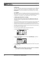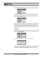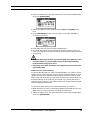
1
Machinedrum SPS-1 USER’S MANUAL for Machinedrum SPS-1 OS 1.12. This manual is copyright (C) 2001-2002 Elektron ESI AB. All
reproduction without written authorization is strictly prohibited. The information in this manual may change without notice. Elektrons product
names, logotypes, titles, words or phrases may be registered and protected by Swedish and international law. All other brand or product
names are trademarks or registered trademarks of their respective holders.
Machinedrum SPS-1 USER’S MANUAL
INTRODUCTION...........................................................................................................1-1
CONVENTIONS IN THIS MANUAL..................................................................................................... 1-1
THE STORY OF THE MACHINEDRUM ....................................................................... 1-3
MACHINEDRUM SPS-1 MAIN FEATURES ........................................................................................ 1-3
USER INTERFACE AND CONNECTORS ....................................................................1-5
FRONT PANEL .................................................................................................................................... 1-5
REAR CONNECTORS ........................................................................................................................ 1-7
RACK MOUNT KIT (ACCESSORY) .................................................................................................... 1-8
RACK MOUNT KIT ASSEMBLY ..................................................................................................... 1-8
CONNECTING THE UNIT ................................................................................................................... 1-8
CARE INSTRUCTIONS ....................................................................................................................... 1-8
THE LCD USER INTERFACE.......................................................................................1-9
LAYER EDIT AND WINDOWS ............................................................................................................ 1-9
QUICK START ............................................................................................................1-10
PLAYING AND TWEAKING DRUM SOUNDS................................................................................... 1-10
USING THE TRACK EFFECTS......................................................................................................... 1-10
SELECTING AND PLAYING A PATTERN ......................................................................................... 1-10
RECORDING A PATTERN USING GRID COMPOSING .................................................................. 1-11
SETTING THE ACCENT PATTERN .................................................................................................. 1-11
SETTING THE SWING PATTERN..................................................................................................... 1-11
PATTERN LIVE RECORDING ........................................................................................................... 1-12
PARAMETER LOCKS........................................................................................................................ 1-12
THE SOUND SYNTHESIS OF MACHINEDRUM ....................................................... 1-13
MACHINEDRUM KITS....................................................................................................................... 1-14
LOADING A KIT............................................................................................................................ 1-15
SAVING AND NAMING A KIT ...................................................................................................... 1-15
UNDO KIT..................................................................................................................................... 1-16
DUPLICATING A KIT .................................................................................................................... 1-17
KIT ASSEMBLY ............................................................................................................................ 1-17
SETTING TRIG AND MUTE RELATIONS OF A KIT.................................................................... 1-18
COPY MACHINE .......................................................................................................................... 1-18
CLEAR MACHINE ........................................................................................................................ 1-19
MACHINE PARAMETER EDITING.................................................................................................... 1-19
TRACK EFFECTS ............................................................................................................................. 1-21
AMPLITUDE MODULATOR.......................................................................................................... 1-21
TRACK EQ ................................................................................................................................... 1-21
FILTER.......................................................................................................................................... 1-22
THE SAMPLE RATE REDUCER .................................................................................................. 1-22
ROUTING .......................................................................................................................................... 1-23
DISTORTION................................................................................................................................ 1-23
TRACK VOLUME ......................................................................................................................... 1-23
TRACK PANNING ........................................................................................................................ 1-23
DELAY SEND ............................................................................................................................... 1-23
REVERB SEND ............................................................................................................................ 1-24
LFO CONTROL ............................................................................................................................ 1-24
STEREO MASTER EFFECT SYSTEM ............................................................................................. 1-24
THE “RHYTHM ECHO” DELAY .................................................................................................... 1-25
THE “GATE BOX” REVERB ......................................................................................................... 1-26
EQ................................................................................................................................................. 1-26
THE “DYNAMIX” DYNAMICS PROCESSOR ............................................................................... 1-27
I of IV
LOW FREQUENCY OSCILLATORS (LFO) ....................................................................................... 1-28
LFO EDIT...................................................................................................................................... 1-28
THE SEQUENCER .....................................................................................................1-30
CLASSIC VS EXTENDED ................................................................................................................. 1-30
CLASSIC EDITING ....................................................................................................................... 1-30
EXTENDED EDITING................................................................................................................... 1-30
TEMPO .............................................................................................................................................. 1-31
THE TEMPO SCREEN ................................................................................................................. 1-31
TAP TEMPO ................................................................................................................................. 1-31
EXTERNAL SYNCRONISATION.................................................................................................. 1-31
PATTERN MODE ............................................................................................................................... 1-32
PATTERN SELECTION ................................................................................................................ 1-32
PATTERN CHAINING ................................................................................................................... 1-32
SCALE SETUP .................................................................................................................................. 1-32
COMPOSING A PATTERN ................................................................................................................ 1-33
GRID COMPOSING...................................................................................................................... 1-33
LIVE RECORDING ....................................................................................................................... 1-34
TRACK COPY............................................................................................................................... 1-35
CLEAR TRACK............................................................................................................................. 1-35
PATTERN COPY .......................................................................................................................... 1-35
CLEAR PATTERN......................................................................................................................... 1-36
ACCENT TRACK ............................................................................................................................... 1-37
TRACK MUTING................................................................................................................................ 1-37
THE TRACK MUTE WINDOW...................................................................................................... 1-37
MINIMISING THE MUTE WINDOW ............................................................................................. 1-38
SWING............................................................................................................................................... 1-38
THE SWING WINDOW................................................................................................................. 1-38
THE SWING PATTERN ................................................................................................................ 1-39
PARAMETER LOCKS........................................................................................................................ 1-39
PARAMETER LOCKS IN GRID COMPOSING MODE................................................................. 1-39
PARAMETER LOCKS IN LIVE RECORDING MODE .................................................................. 1-40
PARAMETER LOCK SLIDE............................................................................................................... 1-40
SONG MODE..................................................................................................................................... 1-42
LOAD SONG................................................................................................................................. 1-42
PLAYING A SONG........................................................................................................................ 1-42
NAVIGATING A SONG ................................................................................................................. 1-43
SONG EDITING............................................................................................................................ 1-43
SONG ROW OFFSETS AND LENGTHS...................................................................................... 1-45
SONG TRANSPORT .................................................................................................................... 1-45
SONG LOOPS AND JUMPS ........................................................................................................ 1-45
SONG MUTES.............................................................................................................................. 1-46
SAVE SONG ................................................................................................................................. 1-47
GLOBAL SETTINGS ...................................................................................................1-48
MIDI BASE CHANNEL....................................................................................................................... 1-48
MAP EDITOR..................................................................................................................................... 1-49
SYSEX SEND .................................................................................................................................... 1-50
ALL DATA SYSEX SEND ............................................................................................................. 1-51
GLOBAL SYSEX SEND................................................................................................................ 1-51
SONG + PATTERN (+ KIT) SYSEX SEND ................................................................................... 1-51
PATTERN (+ KIT) SYSEX SEND.................................................................................................. 1-51
KIT SYSEX SEND ........................................................................................................................ 1-52
SYSEX RECEIVE .............................................................................................................................. 1-52
ORIGINAL PLACE SYSEX RECEIVE .......................................................................................... 1-52
II of IV
SPECIFIC PLACE SYSEX RECEIVE........................................................................................... 1-53
TRACK ROUTINGS........................................................................................................................... 1-54
TRIG .................................................................................................................................................. 1-55
SYNC ................................................................................................................................................. 1-56
SYNC TEMPO IN ......................................................................................................................... 1-56
SYNC CTRL IN............................................................................................................................. 1-56
SYNC OUT ................................................................................................................................... 1-56
TECHNICAL INFORMATION ......................................................................................1-58
FACTORY DEFAULT MEMORY RESET ........................................................................................... 1-58
SPECIFICATIONS ............................................................................................................................. 1-58
GLOSSARY.................................................................................................................1-60
CREDITS .................................................................................................................... 1-61
PRODUCT DESIGN AND DEVELOPMENT...................................................................................... 1-61
ADDITIONAL DESIGN....................................................................................................................... 1-61
FACTORY DEFAULT SOUND DESIGN ............................................................................................ 1-61
CONTACT INFORMATION .........................................................................................1-62
ELEKTRON SUPPORT ..................................................................................................................... 1-62
MACHINEDRUM WEBSITE .............................................................................................................. 1-62
ELEKTRON WEBSITE ...................................................................................................................... 1-62
POSTAL ADDRESS........................................................................................................................... 1-62
DELIVERY ADDRESS....................................................................................................................... 1-62
Appendix A: MACHINE REFERENCE
TRX......................................................................................................................................................A-1
BASS DRUM “TRX-BD”..................................................................................................................A-1
BASS DRUM “TRX-B2” ..................................................................................................................A-1
SNARE DRUM “TRX-SD” ...............................................................................................................A-1
TOM “TRX-XT” ...............................................................................................................................A-1
CLAP “TRX-CP”..............................................................................................................................A-3
RIM SHOT “TRX-RS” .....................................................................................................................A-3
COW BELL “TRX-CB” ....................................................................................................................A-3
CLOSED HIHAT “TRX-CH” ............................................................................................................A-3
OPEN HIHAT “TRX-OH” .................................................................................................................A-3
CYMBAL “TRX-CY” ........................................................................................................................A-3
MARACAS “TRX-MA” .....................................................................................................................A-3
CLAVES “TRX-CL” .........................................................................................................................A-4
CONGAS “TRX-XC” .......................................................................................................................A-4
EFM .....................................................................................................................................................A-4
BASS DRUM “EFM-BD” .................................................................................................................A-4
SNARE DRUM “EFM-SD” ..............................................................................................................A-4
TOM “EFM-XT” ...............................................................................................................................A-4
CLAP “EFM-CP” .............................................................................................................................A-4
RIMSHOT “EFM-RS” ......................................................................................................................A-5
COWBELL “EFM-CB” .....................................................................................................................A-5
HIHAT “EFM-HH” ............................................................................................................................A-5
CYMBAL “EFM-CY” ........................................................................................................................A-5
E12 ......................................................................................................................................................A-6
BASS DRUM “E12-BD” ..................................................................................................................A-6
SNARE DRUM “E12-SD”................................................................................................................A-6
HIGH TOM “E12-HT” ......................................................................................................................A-6
LOW TOM “E12-LT”........................................................................................................................A-6
CLAP “E12-CP” ..............................................................................................................................A-6
RIMSHOT “E12-RS” .......................................................................................................................A-6
III of IV
COW BELL “E12-CB” .....................................................................................................................A-7
CLOSED HIHAT “E12-CH” .............................................................................................................A-7
OPEN HIHAT “E12-OH”..................................................................................................................A-7
RIDE CYMBAL “E12-RC” ...............................................................................................................A-7
CRASH CYMBAL “E12-CC” ...........................................................................................................A-7
BRUSHED SNARE “E12-BR” .........................................................................................................A-7
TAMBOURINE “E12-TA” .................................................................................................................A-8
TRIANGLE “E12-TR” ......................................................................................................................A-8
SHAKER “E12-SH” .........................................................................................................................A-8
BONGO CONGO “E12-BC” ............................................................................................................A-8
P-I ........................................................................................................................................................A-9
BASS DRUM “PI-BD”......................................................................................................................A-9
SNARE DRUM “PI-SD”...................................................................................................................A-9
TOM “PI-XT” ...................................................................................................................................A-9
RIMSHOT “PI-RS” ..........................................................................................................................A-9
METALLICA “PI-ML” .......................................................................................................................A-9
MARACAS “PI-MA”.........................................................................................................................A-9
HI HAT “PI-HH” ...............................................................................................................................A-9
RIDE CYMBAL “PI-RC” ................................................................................................................A-10
CRASH CYMBAL “PI-CC” ............................................................................................................A-10
MIDI MACHINES “MID” ..................................................................................................................... A-11
SYNTHESIS MENU ...................................................................................................................... A-11
Effects ........................................................................................................................................... A-11
Routing.......................................................................................................................................... A-11
GND ...................................................................................................................................................A-12
SINUS “GND-SN” .........................................................................................................................A-12
NOISE “GND-NS” .........................................................................................................................A-12
IMPULSE “GND-IM”......................................................................................................................A-12
INP .....................................................................................................................................................A-12
INPUT GATE A/B “INP-GA/B”.......................................................................................................A-12
INPUT FILTER FOLLOWER A/B “INP-FA/B”................................................................................A-12
INPUT ENVELOPE A/B “INP-EA/B” .............................................................................................A-12
Appendix B:
MIDI CONTROL REFERENCE
DEFAULT MIDI MAPPINGS ........................................................................................................... 1-1
CTRL-CHANGE MAPPINGS .......................................................................................................... 1-1
Appendix C:
IV of IV
SYSEX REFERENCE
Machinedrum SPS-1
USER’S MANUAL
Copyright 2001-2002 ELEKTRON ESI AB
INTRODUCTION
Thank you for choosing the Machinedrum SPS-1, Synthetic Percussion
Sequencer. The SPS-1 is a powerful and intuitive tool for creating percussion sounds and rhythm sequences. We in the Elektron development team
would like to take this opportunity to thank you for your choice of music creation tool. We hope that you will have a lot of fun while exploring the vast
possibilities of the Machinedrum. To make the most of the SPS-1, we would
like you to carefully read the relevant parts of this manual before operating
the instrument.
CONVENTIONS IN THIS MANUAL
In this manual, we have used certain conventions for indicating input using
knobs and buttons through the user interface. These conventions are listed
below:
Buttons are written in upper case with bold style, and they are enclosed in
brackets. For instance, the button “function” on the main panel is written
[FUNCTION].
Knobs are written in upper case with bold, italic style. For instance, the knob
“level” is written LEVEL.
LED indicators like the record light are written <RECORD>.
1
INTRODUCTION
The following symbols are used throughout the manual:
This symbol indicates information that you need to pay attention to.
This symbol indicates a tip that might make it easier interacting with
the SPS-1.
This symbol is not used, but it shows a nice ear.
2
Machinedrum SPS-1 USER’S MANUAL
THE STORY OF THE MACHINEDRUM
THE STORY OF THE MACHINEDRUM
The Machinedrum SPS-1 is a music instrument that presents new methods
for music synthesis and creation. It also brings a heritage from the classic
drum machines.
The drum machine concept is more than 30 years old. Around the same
time that Bob Moog released his first commercial synthesizer for keyboard
players, the first consumer drum machines were also made available.
Although primitive in design with only pre-programmed patterns to offer,
they laid the foundation for a new area of electronically aided music and
sound creation.
What followed has formed a good part of the percussive basis for modern
music. The drum machines from Roland (the TR-series), Linn and Simmons
are legendary and highly regarded for their individual synthetic sound. The
analogue drum machines were actually advanced synthesizers, specially
designed for creating a specific percussive sound. Today respect is gained
not by recreating the sound of an acoustic drum, but by adding to the tonal
palette of percussion. The method of “grid programming” has also offered a
creative approach to forming rhythms.
Percussion synthesis has now been a neglected area for many years.
Straight static samples can never replace the full possibilities of a powerful
drum synthesizer / sequencer. With the Machinedrum, we have incorporated the best ideas from the classic drum machines, using specially
designed “machines” for many types of percussion, combined with new
rhythm composing possibilities to make the SPS-1 the state of the art drum
synthesizer and sequencer.
MACHINEDRUM SPS-1 MAIN FEATURES
The SPS-1 is built from three parts - the percussion synthesizer, the effect
system and the percussion sequencer.
The synthesizer holds 16 drum generating synthesizers - machines - simultaneously. Each of the machines is designed for creating a specific drum
sound, such as bass drum or claves, from a set of parameters.
The effect system consists of the Track Effect System and the Stereo Master Effect System. The Track Effect System supplies Amplitude Modulation,
1-band EQ, Resonant lo/band/hi-pass filter, Sample Rate Reduction and
Distortion tied to each audio track. These effects can be used tightly
together with the machines to form the sound.
The Stereo Master Effect System consists of the Rhythm Echo, Gate
Reverb, EQ and Dynamics. These effects operate on the mixed main output
signal.
Machinedrum SPS-1 USER’S MANUAL
3
THE STORY OF THE MACHINEDRUM
• SPS-1 features the MD-synths TRX, EFM, E12 and PI that generate
percussive sounds from different theories and practices.
• The MD-synths offer specialised machines. Each machine is
designed for creating a specific drum sound, such as bass drum or
claves.
• The machines are arranged in kits together with settings for the
Track Effects, giving a total of 16 fully user controlled real time synthesized percussion sounds.
• Each machine has up to eight parameters, which can be tweaked in
real time by the user.
• A machine used in a kit is assigned to one of the 16 tracks controlled by the sequencer.
• Each track has its own Track Effect, consisting of Amplitude Modulation, 1-band EQ, Resonant lo/band/hi-pass filter, Sample Rate
Reduction and Distortion.
• The sequencer has full control over the machines, as well as the
Track Effects and Routing.
• The Stereo Effect System consists of the Rhythm Echo, Gate
Reverb, EQ and Dynamix compressor. Each track has separate send
routing for the Rhythm Echo and the Gate Reverb.
4
Machinedrum SPS-1 USER’S MANUAL
USER INTERFACE AND CONNECTORS
USER INTERFACE AND CONNECTORS
FRONT PANEL
The Machinedrum SPS-1 front panel:
1.
Master volume control. Sets the volume for the main output and headphone jack.
2.
The <SOUND SELECTION> leds. Used for indicating the current track
in focus and for showing which tracks are triggered.
3.
[CLASSIC/EXTENDED] mode change key. Changes current editing
mode between <CLASSIC> and <EXTENDED>.
4.
SOUND SELECTION wheel. Selects tracks and changes values during
editing.
5.
[FUNCTION] key. Press and hold it for accessing the secondary function of another key.
6.
[BANK] key. Used for switching between bank group A to D and E to H.
7.
[A/E] key. Hold this key while pressing one of the [DRUM] keys to
select a pattern in either the A or the E bank, depending on which bank
group is selected. The secondary function is track muting.
8.
[B/F] key. Hold this key while pressing one of the [DRUM] keys to
select a pattern in either the B or the F bank, depending on which bank
group is selected. The secondary function is accent pattern editing.
9.
[C/G] key. Hold this key while pressing one of the [DRUM] keys to
select a pattern in either the C or the G bank, depending on which bank
group is selected. The secondary function is the pattern swing settings.
10. [D/H] key. Hold this key while pressing one of the [DRUM] keys to
select a pattern in either the D or the H bank, depending on which bank
group is selected. The secondary function is slide pattern editing.
11. The LCD graphics interface display.
Machinedrum SPS-1 USER’S MANUAL
5
USER INTERFACE AND CONNECTORS
12. [ENTER/YES] key. Used for entering sub-menus and for confirming
choices.
13. [EXIT/NO] key. Used for exiting the current menu and for deselecting
options.
14. The arrow keys. Used for menu navigation. They are called [UP],
[DOWN], [LEFT] and [RIGHT].
15. LEVEL knob. Sets the overall volume level of the track in focus.
16. [TEMPO] key. Brings up the tempo menu. The current tempo is always
indicated by the speed the <TEMPO> led is flashing.
17. DATA ENTRY knobs. Used for tweaking parameters for the machines
and effects.
•
The DATA ENTRY and LEVEL knobs allow accelerated editing, by
pressing the knob while turning it.
18. [SYNTHESIS/EFFECTS/ROUTING] toggle key. Switches the editing
focus for the Data Entry encoders. The active page is indicated by the
<SYNTHESIS>, <EFFECTS> and <ROUTING> leds. The secondary
function is calling the LFO edit menu.
19. [RECORD] key. Toggles grid edit mode on/off. Starts live recording if
hold while pressing [PLAY]. In grid edit mode, the <RECORD> led
gives a steady light, while in live recording it flashes. The secondary
function is copy.
20. [PLAY] key. Initiates playback of a pattern or song. Pressing [PLAY] a
second time pauses playback. The secondary function is the clear
operation.
21. [STOP] key. Stops the playback of a pattern or song. The secondary
function is paste.
• The copy clear and paste keys are tied to different data depending
on the context where they are used. Their use will be described in
their respective parts of this manual.
22. [PATTERN/SONG] key. Switches between pattern and song sequencer
mode. The current sequencer mode is indicated by the <PATTERN>
and <SONG> leds. The secondary function is calling the global edit
menu.
23. [KIT] key. Calls the kit menu. The secondary function is calling the song
menu.
24. [DRUM] keys 1 to 16. Used for direct trigging of machine per track, and
for editing the notes in grid edit mode. Also used for choosing pattern, if
pressed while holding [A-H] keys. Also used for selecting track when
pressed while holding [FUNCTION].
25. [SCALE] key. Switches the editing focus of the [DRUM] keys between
the upper and lower 16 steps, if the scale length is longer than 16. The
high/low focus is indicated by the <1/32:1> and <1/32:2> leds. For
scale lengths up to 16 steps, the <1/16> led will stay lit and pressing
[SCALE] will have no effect. The secondary function is calling the scale
setup menu.
6
Machinedrum SPS-1 USER’S MANUAL
USER INTERFACE AND CONNECTORS
REAR CONNECTORS
The Machinedrum SPS-1 rear connectors:
1. Power on/off switch.
2. AC 6Volts power in.
• Caution! Use only an Elektron-approved power supply with your
Machinedrum SPS-1. It must be equipped with a 5.5mm (2.5mm
inner diameter) plug. The electrical specifications are 6 Volts AC at
2000mA, 50/60Hz. Using the wrong type of adapter may result in
damage to your unit. Damage caused by the use of incorrect power
supply is not covered by warranty. If you are unsure about your
power supply, please contact Elektron support.
3. MIDI Thru.
4. MIDI Out.
5. MIDI In.
6. Input B.
7. Input A.
8. Individual output F.
9. Individual output E.
10.Individual output D.
11.Individual output C.
12.Main out right / Individual output B.
13.Main out left / Individual output A.
14.Stereo headphones output.
Machinedrum SPS-1 USER’S MANUAL
7
USER INTERFACE AND CONNECTORS
RACK MOUNT KIT (ACCESSORY)
The Machinedrum SPS-1 can be rack mounted in a standard 19” rack, using
the SPS-1 rack mount kit which is ordered separately. When rack mounted,
the SPS-1 occupies four standard height units plus additional space needed
to accommodate cables plugged into the unit at the back.
RACK MOUNT KIT ASSEMBLY
Make sure that you have a screwdriver which is in good condition, and
which has the right size. Use the included “M3” sized screws to secure the
rack mount consoles on each side of the Machinedrum. Make sure that all
screws are fastened for secure operation of the unit.
CONNECTING THE UNIT
Before you start connecting the SPS-1 Machinedrum to other units, make
sure that everything is switched off.
1. Insert the supplied AC adapter into the wall socket, and connect the small
plug into the rear of the Machinedrum unit.
2. Connect the main out L/R from the Machinedrum to your mixer or ampli-
fier.
3. If MIDI control is desired, connect MIDI Out from the Machinedrum to the
device that you wish to send data to. Connect the MIDI In from the device
that you wish to receive data from. The MIDI Thru port is “echoing” the
data coming in from the MIDI In port, so it can be used for daisy chaining
other MIDI units.
4. Switch on all units.
CARE INSTRUCTIONS
To ensure many years of trouble free operation, please follow the advice
below:
• Never use any aggressive cleaners on the casing or the LCD overlay. Remove dust, dirt and fingerprints with a soft dry cloth. More
persistent dirt can be removed with a slightly damp cloth using only
water.
• Never use sharp objects near the display to avoid scratches or damage. Also avoid applying any pressure to the display itself.
• When transporting the Machinedrum, try to use the box in which it
was originally shipped with the padding supplied, or equivalent
packaging such as the specially designed Machinedrum transportation bag for sale at the Elektron webpage.
• Make sure that you place the unit on a stable surface before use. If
you mount the unit in a rack, be sure to tighten all four screws in the
rack mount holes.
• The memory used for storing patches and kits is powered by a battery inside the unit. It will hold data at least 6 years before needing
replacement. If the battery needs replacement, the “battery low”
message will appear in the display. Contact Elektron support or your
nearest repair center.
8
Machinedrum SPS-1 USER’S MANUAL
THE LCD USER INTERFACE
THE LCD USER INTERFACE
The center of the Machinedrum SPS-1 editing is the LCD display. The main
interface screen is shown below:
1. The current tempo displayed with one decimal.
2. Four rectangular boxes showing the playback position in the pattern.
3. The playback/recording status shown by the standard “rec”, “play” and
“stop” symbols.
4. Name and number of the current kit.
5. Specification of the MD-synth, machine and current data entry focus.
6. Level bar showing the overall volume level of the machine on the active
track.
7. Up to eight control data entry values. They show what the Data entry
encoders control and also indicate the current data entry values. When
two parameters depend on each other in some way, they will have a small
“clip” between them as shown below:
LAYER EDIT AND WINDOWS
When a function which puts a window on top of the base control window is
called, it will change the function of certain buttons and/or encoders. The
buttons that are not used or blocked can still be used to control the layer
underneath. For example, when you have called the tempo function it will
make use of the SOUND SELECTION wheel, but you can still use the DATA
ENTRY knobs to control the track in focus.
All windows can be closed using the [EXIT/NO] key.
Machinedrum SPS-1 USER’S MANUAL
9
QUICK START
QUICK START
This quick start will guide you through some of the basic operations to allow
you to start using the SPS-1. First connect it as described in section “CONNECTING THE UNIT”, on page 8.
• The DATA ENTRY knobs have accelerated editing when pressed. By
default, the knobs increase/decrease in steps of +1/-1. When
pressed, the step length is higher, allowing quicker adjustments.
PLAYING AND TWEAKING DRUM SOUNDS
1. Press the [KIT] key.
2. Select the load kit icon in the menu and press [ENTER/YES]. You will
now be presented with a list where you can select a kit name using the
[UP] and [DOWN] keys.
3. Press [ENTER/YES] to load the kit. Exit the menu by pressing [EXIT/NO]
4. Now press any of the 16 [DRUM] keys to play the corresponding drum
assigned to that track. You will notice that the drum select leds in the
upper left corner will light up accordingly.
5. Turn the SOUND SELECTION wheel so that the <BD> led is lit. <BD> is
now the “active track”, and track relative editing will be directed to the
bass drum track.
6. Make sure that the <SYNTHESIS> led is lit by pressing the toggle key
[SYNTHESIS/EFFECTS/ROUTING].
7. Now, turn any of the DATA ENTRY knobs to tweak the corresponding
bass drum machine specific parameter. You can trigger the sound by
pressing [DRUM] key 1 while you are turning the DATA ENTRY knob A to
hear the pitch change.
USING THE TRACK EFFECTS
1. Press the [SYNTHESIS/EFFECTS/ROUTING] key until the <EFFECTS>
led is lit.
2. You can now edit the track effect parameters for the active track by turn-
ing the DATA ENTRY knobs.
SELECTING AND PLAYING A PATTERN
1. Make sure you have loaded a kit. See the previous section for details on
this.
2. Press the [CLASSIC/EXTENDED] key until the <CLASSIC> led is lit. You
are now in classic mode. The difference between “CLASSSIC” and
“EXTENDED” mode will be explained later on in this manual.
3. Check the [PATTERN/SONG] key so that the <PATTERN> led is lit.
4. Press the [BANK GROUP] key to select between banks A to D or E to H.
Select pattern bank A to D for this demonstration.
10
Machinedrum SPS-1 USER’S MANUAL
QUICK START
5. To select pattern A01, press and hold the pattern selection key [A/E] and
then the [DRUM] key 1. You can see the currently selected pattern in the
lower left corner of the display.
6. To play this pattern, simply press the [PLAY] key. The pattern starts play-
ing and starts at the beginning again when it has reached its end. Pressing [PLAY] while playing pauses the playback.
7. To change pattern during playback, simply select a pattern the same way
as in step 4. The display will show the selected pattern beside the current
one, but with an arrow pointing towards it. This indicates that once the
current pattern has come to its end, the selected pattern will begin to play.
8. To stop the playback of the pattern, press the [STOP] key.
RECORDING A PATTERN USING GRID COMPOSING
1. You can input notes into a pattern in the sequencer, both while it is play-
ing or while it is currently stopped. Press the [RECORD] key to start grid
recording. The <RECORD> led will be lit the whole time during the process.
2. Select the active track using the SOUND SELECTION wheel.
3. Press the [DRUM] keys to insert 16th notes where you wish to have the
machine triggered. Pressing the same [DRUM] key once more removes
the note.
4. To edit other tracks, change the active track using the SOUND SELEC-
TION wheel.
SETTING THE ACCENT PATTERN
1. Hold [FUNCTION] and press key [B/F] to access the accent screen.
2. On this screen you can set the level of accentuation on all notes selected
by the accent pattern. Use the SOUND SELECTION wheel to set the
level.
3. The accent pattern is shown on all <DRUM> leds above the [DRUM] keys
as long as you are in the accent screen. To accent a note, simply select it
by pressing the [DRUM] key. To remove the accent, press the same key
again.
SETTING THE SWING PATTERN
1. Hold [FUNCTION] and press key [C/G] to access the swing screen.
2. On this screen you can set the amount of swing on notes selected by the
swing pattern. Use the SOUND SELECTION wheel to set the level. A
level of approximately 65% should allow you to hear the effect.
3. The swing pattern is shown on all <DRUM> leds above the [DRUM] keys
as long as the swing screen is active. The default swing pattern is to
affect every second note, starting with the second. The swing pattern can
be changed using the [DRUM] keys, but for normal rhythm styles the
default pattern is better left as it is.
Machinedrum SPS-1 USER’S MANUAL
11
QUICK START
PATTERN LIVE RECORDING
1. The live recording mode of a pattern allows you to play the sounds in the
kit while the pattern is playing. To start this mode, press and hold
[RECORD] and then [PLAY].
2. You can now “play” all the machines in the kit directly on the [DRUM]
keys. All played notes will be quantised to 16th notes, and you will be
able to hear them the next time the pattern starts all over.
3. The pattern will loop until you press the [STOP] key.
PARAMETER LOCKS
1. Press the [CLASSIC/EXTENDED] key until the <EXTENDED> led is lit.
You are now in extended mode. The difference between “CLASSSIC” and
“EXTENDED” mode will be explained later on in this manual.
2. Now it is possible to lock parameters to a specific note in the pattern. In
grid edit mode, hold a [DRUM] key and then tweak a parameter. The
parameter adjusted will be inverted to indicate that it now is locked to the
value you set. The corresponding <DRUM> LED will flash rapidly to indicate that a parameter is locked for that step.
3. In live recording mode, you can lock parameters by tweaking the knobs
while recording.
4. Parameters can be locked for all track simultaneously. To lock parameters
for a new track, just repeat the sequence from step 2 above.
5. To remove a lock, enter grid edit mode and press the [DRUM] key on the
locked note twice. This removes the lock and restores the note to be triggered. You can also hold the [DRUM] key while clicking one of the parameters locked. You will see that the inversion disappears and that single
parameter lock is removed.
12
Machinedrum SPS-1 USER’S MANUAL
THE SOUND SYNTHESIS OF MACHINEDRUM
THE SOUND SYNTHESIS OF MACHINEDRUM
The basic sound generating unit in the Machinedrum is a machine. Each
machine is designed for generating a specific drum such as bassdrum,
snare or claves. However, this does not mean that you only have to use it for
generating the sound indicated by its name.
The machines are grouped in MD-synths. You could see it as if the
machines in an MD-synth belong to the same family. In the EFM family,
there is a total of 8 machines for bass drum, snare drum, closed hi-hat etc.
Despite the fact that each machine is based on the family synthesis, each
machine can have a unique parameter set. The parameters are selected
individually to give the user the best control of the machines.
The MD-synths and their parameters are covered in “Appendix A:
MACHINE REFERENCE“.
Each of the 16 tracks can have any machine assigned to it. The assignment
of machines and their parameter settings are collected in kits. Editing the
kits is discussed in section “KIT ASSEMBLY”, on page 17.
Every track has its dedicated effect module, called the Track Effect System.
Each track effect delivers hi/lo/band-pass resonant 24-db filter, amplitude
Machinedrum SPS-1 USER’S MANUAL
13
THE SOUND SYNTHESIS OF MACHINEDRUM
modulation, 1-band eq and bit reduction. The settings of effects are saved in
the kits as well. The Track Effect System is explained in section “TRACK
EFFECTS”, on page 21.
The routing page delivers control of pan, delay send, reverb send, output
distortion and volume. The routing options are discussed in section “ROUTING”, on page 23.
The SPS-1 offers 16 assignable Low Frequency Oscillators (LFO’s) that you
can connect to any machine, track effect or routing parameter. More about
the LFO’s can be found in section “LOW FREQUENCY OSCILLATORS
(LFO)”, on page 28.
MACHINEDRUM KITS
Machinedrum kits hold the information specified below:
•
•
•
•
•
•
The machines selected for each of the 16 tracks
Parameter settings for the 16 machines
Parameter settings for the Track Effect System
Parameter settings for routing
Parameter settings for the Stereo Master Effect system
The Kit name
All kits are battery backed up and user definable. A total of 64 user kits can
be stored in memory.
• You can either assemble a kit from scratch or modify an existing one
and then save it to a new position. Building your kit from an existing
one is often quicker.
The kit window is called with the [KIT] key.
14
Machinedrum SPS-1 USER’S MANUAL
THE SOUND SYNTHESIS OF MACHINEDRUM
LOADING A KIT
1. Open the kit window.
2. Use the arrow keys to move to the “LOAD” icon. Press [ENTER/YES] to
call the LOAD KIT menu.
3. The screen presents a list of the kits stored in memory. Use the [UP] and
[DOWN] keys to choose among the 64 kit slots. Press [ENTER/YES] to
load the kit of your choice.
If you want to exit without loading a kit, press [EXIT/NO].
SAVING AND NAMING A KIT
1. Open the kit window.
2. Use the arrow keys to move to the “SAVE” icon. Press [ENTER/YES] to
open the SAVE KIT menu.
3. The screen presents a list of the kits stored in memory. Use the [UP] and
[DOWN] keys to choose among the 64 kit slots. Press [ENTER/YES] to
select the slot where you want to save your kit.
Machinedrum SPS-1 USER’S MANUAL
15
THE SOUND SYNTHESIS OF MACHINEDRUM
4. The window opening will allow you to name the kit:
Use the SOUND SELECTION wheel or the [UP] and [DOWN] keys to cycle
through the letters. The [LEFT] and [RIGHT] keys move the cursor backwards and forwards on the line.
5. Pressing the [FUNCTION] key gives access to the “high score” selection
method, in which you see all characters at the same time. Keep the
[FUNCTION] key hold while navigating using the [LEFT], [RIGHT], [UP]
and [DOWN] buttons. Release the [FUNCTION] key, when you have
found the right letter.
6. When the kit naming procedure is completed, press [ENTER/YES] to
save it.
7. If you want to exit without saving the kit, press [EXIT/NO].
UNDO KIT
There is a special kit in the first position of the kit list called the “UNDO KIT”.
When you have made unsaved changes to a kit and a new one is loaded,
the unsaved old kit will be stored in the “UNDO KIT” position. When saving a
kit over an occupied position in the kit list, the overwritten kit will also be
saved in the “UNDO KIT”.
You can load the “UNDO KIT” to restore your most recent unintentionally
lost kit. This can often be useful in extended mode, where a pattern change
automaticly can change kit. When you have needed to restore your kit using
the undo kit, don’t forget to save it.
16
Machinedrum SPS-1 USER’S MANUAL
THE SOUND SYNTHESIS OF MACHINEDRUM
DUPLICATING A KIT
To duplicate a kit, first load it and then save it in a new kit slot. For loading a
kit, see section “LOADING A KIT”, on page 15. For saving a kit, see section
“SAVING AND NAMING A KIT”, on page 15.
KIT ASSEMBLY
To assemble a kit, you need to select and assign your machines for each
track. First open the KIT window.
1. Use the arrow keys to move to the “edit” icon. Press [ENTER/YES] to
open the edit window.
2. The Edit kit window is used for selecting machines from the synthesizer
and machine menus, and for specifying Mute and Trig groups. The
<SOUND SELECTION> leds indicate which track you are editing. This is
also shown at the top of the edit kit window. To change track position, turn
the SOUND SELECTION wheel left or right.
3. After choosing what track you want to do changes for, use [LEFT] and
[RIGHT] to choose between the “SYNTH”, “MACHINE” and “RELATE”
columns. [LEFT] and [RIGHT] are also used for selecting “MUTE/TRIG
POS” focus in the “RELATE” column. Once you have entered a column, it
will be highlighted and now you can use [UP] and [DOWN] to choose
from the available options.
Select the MD-synth by first selecting the “SYNTH” menu with [LEFT]
and [RIGHT], then move the focus using [UP] and [DOWN] to select the
MD-synth of your choice.
4. Press [RIGHT] once to move the focus to the “MACHINE” column. Select
the machine using [UP] and [DOWN].
5. Finally you need to press the [ENTER/YES] key to confirm your selection.
Machinedrum SPS-1 USER’S MANUAL
17
THE SOUND SYNTHESIS OF MACHINEDRUM
• The MD-synth and the machine currently selected are shown as
inverted text. The focus, when moved away from the original selection, is a square window. Once [ENTER/YES] is pressed, the current
focus will be selected, thus changing the focus to inverted text.
SETTING TRIG AND MUTE RELATIONS OF A KIT
Mute groups are useful for interleaving drums such as open and closed hihats. Trig groups can be used for making layered drums, consisting of two
drums on different tracks that are triggered by one drum trig only.
1. In the edit kit menu, move the focus using the [LEFT] and [RIGHT] keys
to the “RELATE, MUTE POS” column. [LEFT] and [RIGHT] are also used
for selecting the “MUTE/TRIG POS” focus.
2. The mute relation is useful for interleaving drums, such as open and
closed hi-hats which are supposed to stop the sound of each other when
played. Use the [UP] and [DOWN] keys to select which track is muted
when the current machine is triggered.
3. The trigger relation is useful for layering sounds. It can either be used to
make a sound richer or to combine two entirely different machines to
make a new type of percussion. Use [LEFT] and [RIGHT] to move to the
“TRIG POS” position. Use the [UP] and [DOWN] keys to select which
track will be played in addition to the current when it is trigged.
• You can not chain trigging relations. If the bass drum is set to trigger the snare, and the snare is set to trigger the cymbal, only the
bassdrum and snare will be played when the bass drum is triggered.
COPY MACHINE
You can copy one machine and its settings from one track to another. It is
also possible to copy the current machine settings to another kit.
1. In the edit kit menu, press and hold [FUNCTION] and then press
[RECORD]. A message saying “COPY MACHINE” appears.
18
Machinedrum SPS-1 USER’S MANUAL
THE SOUND SYNTHESIS OF MACHINEDRUM
2. The settings are placed in the machine copy buffer. Now you can either
change track using the SOUND SELECTION wheel, or load a new kit and
select a target track in there.
3. Once the target track is selected, press and hold [FUNCTION] and then
press [STOP] to paste in the machine settings from the copy buffer. A
message saying “PASTE MACHINE” appears.
• Any previous machine settings will be overwritten when pasting.
• Once the machine is copied into the copy buffer, it can be pasted
many times to several tracks or kits. It will stay in the buffer until it is
replaced by a new one.
CLEAR MACHINE
It is possible to clear a track, so no machine is connected to it.
1. In the edit kit menu, press and hold [FUNCTION] and then [PLAY] to
clear the machine.
2. A track that you have used the clear machine function on will be dis-
played like this:
• The clear machine operation can be undone by performing the clear
track operation one more time. A message “UNDO MACHINE” will
be shown in the display.
MACHINE PARAMETER EDITING
MD Machines are controlled by up to eight parameters that are accessed
with the DATA ENTRY knobs.
Machinedrum SPS-1 USER’S MANUAL
19
THE SOUND SYNTHESIS OF MACHINEDRUM
1. Press the [SYNTHESIS/EFFECTS/ROUTING] key until the <SYNTHE-
SIS> led is lit. The rightmost text of the machine information area at the
bottom left will show “SYNT” for synthesis. The machine parameters are
now controlled by the DATA ENTRY knobs.
2. Changes are not made to the kit unless it is saved. Please see section
“SAVING AND NAMING A KIT”, on page 15 for information about saving
kits.
For more information on specific parameters of the machines, please see
“Appendix A: MACHINE REFERENCE“.
20
Machinedrum SPS-1 USER’S MANUAL
THE SOUND SYNTHESIS OF MACHINEDRUM
TRACK EFFECTS
The Track Effect System is available for all 16 tracks as an extension to the
machine percussion synthesis.
1. To access the track effects, press the [SYNTHESIS/EFFECTS/ROUT-
ING] key until the <EFFECTS> led is lit. The rightmost text of the
machine information area at the bottom left will show “FX” for effects. The
track effect parameters for the active track are now controlled by the
DATA ENTRY knobs.
2. Changes are not made to the kit unless it is saved. Please see section
“SAVING AND NAMING A KIT”, on page 15 for information about saving
kits.
AMPLITUDE MODULATOR
Amplitude modulation is essentially a volume control which is controlled by
a low frequency oscillator. It is also known as a tremolo. The Machinedrum
amplitude modulator has two parameters, frequency and depth. It can go
very high in frequency, allowing extreme effects.
The modulation depth is controlled by the “AMD” parameter.
The modulation frequency is controlled by the “AMF” parameter.
TRACK EQ
Using the 1-band parametric EQ, you can boost or reduce a certain frequency band.
The EQ-frequency is controlled by the “EQF” parameter.
The EQ-gain (which reduces for negative values) is controlled by the “EQG”
parameter.
Machinedrum SPS-1 USER’S MANUAL
21
THE SOUND SYNTHESIS OF MACHINEDRUM
FILTER
The Track Effect System offers a resonant 24dB lo/hi/band-pass filter. The
parameters are untraditional, giving the user control of both the low and high
filter cutoffs, as well as a variable gap bandpass filter.
The illustration below illustrates the function of the filter.
The “FLTF” parameter controls the base filter cutoff frequency. When the
“FLTW” parameter is set to its maximal value, changing the “FLTF” parameter has the function of a high-pass filter. When the “FLTF” parameter is set to
zero, the highpass-Q is disabled.
The “FLTW” parameter controls the filter gap width, that is the distance
between the highpass and lowpass cutoff frequencies. When the “FLTF” is
set to its minimum value, changing the “FLTW” parameter has the function
of a low-pass filter. When the “FLTW” parameter is set to its maximum, the
lowpass-Q is disabled.
The “FLTQ” parameter controls the filter quality “Q” parameter. The “Q”
value controls how much the volume is boosted around the low pass and
high pass filter cut off frequencies.
THE SAMPLE RATE REDUCER
The sample rate reduction effect does exactly what the name suggests. The
“SRR” parameter controls the amount of sample rate reduction.
22
Machinedrum SPS-1 USER’S MANUAL
THE SOUND SYNTHESIS OF MACHINEDRUM
ROUTING
The routing page controls all routing of the sound to distortion, pan/vol, the
effects buses and basic LFO control.
1. To access the routing page, press the [SYNTHESIS/EFFECTS/ROUT-
ING] key until the <ROUTING> led is lit. The rightmost text of the
machine information area at the bottom left will show “ROUT” for routings.
The routing parameters for the active track are now controlled by the
DATA ENTRY knobs.
Changes are not made to the kit unless it is saved. Please see section
“SAVING AND NAMING A KIT”, on page 15 for information about saving
kits.
DISTORTION
The “DIST” parameter controls the signal overload distortion. The distortion
is applied after the synthesis and track effects, and before entering the routing. Each track has individual distortion.
TRACK VOLUME
The “VOL” parameter is a track volume separated from the “LEVEL” overall
gain control. “VOL” is a track parameter that can be locked to separate
notes, and it can be controlled by the LFO system.
See section “LOW FREQUENCY OSCILLATORS (LFO)”, on page 28 for
more information on LFO’s.
See section “PARAMETER LOCKS”, on page 12 for more information on
parameter locks.
• The “LEVEL” overall gain control can not be locked or controlled by
an LFO. For these tasks, use the “VOL” parameter.
TRACK PANNING
The “PAN” parameter controls the stereo pan for the main stereo outputs.
The default value is center. When a track is assigned to an individual output,
the “PAN” parameter has no effect.
DELAY SEND
The “DEL” parameter controls how much signal will be sent to the Machinedrum delay. When a track is assigned to an individual output, the “DEL”
parameter has no effect. See page 25 for more information on the “Rhythm
Echo” delay.
Machinedrum SPS-1 USER’S MANUAL
23
THE SOUND SYNTHESIS OF MACHINEDRUM
REVERB SEND
The “REV” parameter controls how much signal will be sent to the Machinedrum reverb. When a track is assigned to an individual output, the “REV”
parameter has no effect. See page 26 for more information on the “Gate
Box Reverb”.
LFO CONTROL
The “LFOS”, “LFOD” and “LFOM” parameters are the same parameteres as
can be found in the LFO menu. See section “LOW FREQUENCY OSCILLATORS (LFO)”, on page 28, for more information on the LFO system.
STEREO MASTER EFFECT SYSTEM
The Stereo Master Effect System includes the “Rhythm Echo” delay, the
“Gate Box” reverb, the master EQ and the “Dynamix” dynamic processor
(compressor).
The EQ and “Dynamix” processor effect the final stereo main out signal. The
“Rhythm Echo” and “Gate Box” can be fed signals with individual levels
through the Delay and Reverb Send parameters from each of the 16 tracks.
All master effect settings are saved as a part of the kit. The master effect is
only available on the “MAIN” output.
To access the Stereo Master Effect, follow the steps below.
1. Press the [KIT] key to open the kit menu.
2. Move to the “MASTER FX” icon, and press [ENTER/YES] to open the
master effect menu.
3. Use the [LEFT] and [RIGHT] arrow keys to select the “tab” for the effect
you wish to edit.
• Since the master effect settings are stored in the kit, it is important
to save the kit if you wish to keep the changes.
24
Machinedrum SPS-1 USER’S MANUAL
THE SOUND SYNTHESIS OF MACHINEDRUM
THE “RHYTHM ECHO” DELAY
The “Rhythm Echo” delay is a multi-functional single tap delay with realtime
adjustable delay time. Some of its functionality can resemble tape loops and
solid state CCD delays. The delay time is always put in relation to the global
tempo setting.
The “TIME” parameter controls the actual delay time. It is relative to the current tempo, and it is measured in 128th notes. For instance, for a two beat
delay (8 16th notes) “TIME” should be set to 64.
The “MOD” parameter controls the delay time modulation depth.
The “MFRQ” parameter is the delay time modulation frequency.
The “FB” parameter controls the delay feedback amount. The feedback is
taken after the filter but before the out gain control. FB set to central position
with filter totally open gives unity feedback.
“FILTF” is the filter base frequency parameter. Please refer to section “FILTER”, on page 22 for description of the function.
“FILTW” is the filter width parameter. Please refer to section “FILTER”, on
page 22 for description of the function.
“MONO” is the feedback panning control parameter. A low value gives ping
pong style delay, a high value preserves the stereo information, and a central position brings the delay feedback into the central panning position.
“LEV” is the out gain level control of the Rhythm Echo delay.
Machinedrum SPS-1 USER’S MANUAL
25
THE SOUND SYNTHESIS OF MACHINEDRUM
THE “GATE BOX” REVERB
The “Gate Box” Reverb brings HiQ reverb tailored for percussion, with gating possibilities for extra effects.
“DVOL” is the delay to reverb level parameter. This parameter allows the
output of the Rhythm echo to be routed into the Gate box.
“PRED” is the pre-delay parameter. The direct and delay signal mix is
delayed by an amount of time to give the impression of the reverbation arriving after the sound.
“DEC” is the decay time parameter. Decay time is the time it takes for the
reverbation to die out after a sound has ended. The decay parameter is
active in the range of 0.5 to 3 seconds.
“DAMP” is the damping control parameter. Damping decreases the high frequencies to give the impression of soft walls.
“HP” is a high-pass filter, filtering the output from the reverb.
“LP” is a low-pass filter, filtering the output from the reverb.
“GATE” sets the gate time. The reverbated signal is gated after this time, if
the signal level is low. The maximal value for this parameter gives infinite
time - in other words, the gate is off.
“LEV” is the output level parameter of the “Gate Box”.
EQ
The Stereo Master Effect Equalizer is the final frequency shaping tool. It
supplies one low shelf and one high shelf filter that allow you to boost or
reduce the high and low frequencies. It also brings one parametric equalizer
with frequency and Q-control.
“LF” is the cut/boost frequency parameter of the low shelf filter.
“LG” is the low shelf gain parameter that controls how much the low frequencies should be boosted / reduced between -15dB and +15dB.
“HF” is the cut/boost frequency parameter of the high shelf filter.
26
Machinedrum SPS-1 USER’S MANUAL
THE SOUND SYNTHESIS OF MACHINEDRUM
“HG” is the high shelf gain parameter that controls how much the high frequencies should be boosted / reduced between -15dB and +15dB.
“PF” is the parametric EQ frequency parameter, that is the center frequency
of the parametric EQ band.
“PG” is the parametric EQ gain parameter. It controls how much the parametric EQ should boost or reduce between -15dB and +15dB, at the frequency set by the “PF” parameter.
“PQ” is the parametric EQ Q factor. The Q controls the width of the band that
is boosted or reduced by the parametric EQ. High Q-values give a narrow
band.
“GAIN” is the final out volume control. This parameter allows you to adjust
the out volume of the main stereo out.
THE “DYNAMIX” DYNAMICS PROCESSOR
The “Dynamix” dynamics processor is specially designed for compressing
percussive sounds.
“ATCK” controls the attack time, which is the time it takes the volume detector to react to the Attack part of the sound signal. Long attack times let fast
transients through the compressor.
“REL” controls the release time. This is the time it takes the volume detector
to react to the Release part of the sound signal. A long release time lifts the
signal level as a sound decays, flattening the dynamics.
“TRHD” sets the threshold level where the signal starts getting compressed
(from -48 to 0dB).
“RTIO” controls the ratio by which the signal is compressed, when the
threshold level is reached. The ratio has a value in the range 1:1 to 1:256.
“KNEE” controls the soft knee transition. It makes the transition between
compressed and uncompressed signal smoother, by softening the knee. A
low value gives a hard knee.
“HP” is the side chain High pass filter. This parameter highpass filters the
sidechain signal of the Compressor, so that it does not react to bass.
“OUTG” out gain raises the signal level. This is used to make up for the gain
lost in the compressor.
“MIX” controls the cross mix between the compressed signal and the original signal. A high value bypasses the Dynamix processor.
Machinedrum SPS-1 USER’S MANUAL
27
THE SOUND SYNTHESIS OF MACHINEDRUM
LOW FREQUENCY OSCILLATORS (LFO)
Each kit in the Machinedrum has 16 assignable low frequency oscillators
(LFO), which can be used to modulate track parameters. A typical application of an LFO is letting it sweep a filter cut-off frequency.
Each of the 16 LFO’s offers two synchronized waveforms. A mix control
allows the output to be set to any mix between the two waveforms. The
speed of the LFO is synchronized to the global tempo. The LFO’s are by
default mapped to control their own tracks, but they can be set to modulate
any track, including other LFO’s for extra complex modulation waveforms.
However, if “UPDTE” is set to “TRIG” or “HOLD”, the retrigging is only made
by drums from its associated track.
LFO EDIT
To edit an LFO, follow the steps described below.
1. Press [FUNCTION] and hold it, then press [SYNTHESIS/EFFECTS/
ROUTING] to open the LFO edit window.
2. Use the SOUND SELECTION wheel to select the LFO to edit. The first
parameter “TRACK” is the target track for this LFO. Each of the 16 LFO’s
is mapped to its own track by default.
3. Select the parameter you wish the LFO to modulate, using the “PARAM”
control. All Machine, Track Effects and Routing parameters are accessible by the LFO. You can modulate another LFO by targeting the track it is
assigned to, and select either the speed, depth or mix in the “PARAM”
control.
4. “SHP 1” and “SHP 2” select the waveform shapes for the LFO’s. By using
the “SHMIX” mixer, you can choose how much of each you want to use.
“SHMIX” is a balance control, so at its minimum there is only modulation
by the “SHP 1” waveform. At its maximum, there is only modulation by the
“SHP 2” waveform. “SHP 2” waveforms are inverted versions of the ones
available in “SHP 1”.
5. The “UPDTE” parameter sets the update conditions for the LFO. If the
update parameter is set to “FREE”, the LFO will never retrig. “TRIG”
forces the LFO to be re-started each time the track is triggered. “HOLD” is
a sample and hold function, which “freezes” the value of the waveform at
the time when the track is triggered. It will remain frozen until trigged
again.
6. The “SPEED” parameter sets the update speed relative to the tempo in 1/
128 note steps. The modulation depth is set by the “DEPTH” parameter.
• As the LFO settings are stored in the kit, it is important to save the
kit if you wish to keep the changes.
28
Machinedrum SPS-1 USER’S MANUAL
THE SOUND SYNTHESIS OF MACHINEDRUM
• The “SPEED” “DEPTH” and “SHMIX” parameters are also available
from the routing page. As the parameters of the routing page can be
controlled by parameter locks and even another LFO this can be a
source for highly advanced LFO setups.
• If you select the same destination for two different LFO tracks their
outputs will be added, making advanced layered LFO’s possible.
• Cut Clear, Copy and Undo clear functions are available for the
LFO’s.
Machinedrum SPS-1 USER’S MANUAL
29
THE SEQUENCER
THE SEQUENCER
The percussion sequencer is a central part of the Machinedrum sound. It is
designed to be an inspirational tool for pattern based rhythms.
The sequencer is designed both for live and studio use. The patterns can
either be trigged individually from the user interface or by MIDI commands,
or they can be linked together to form a song.
The sequencer has two main modes of operation, called Pattern and Song
mode. We will start by taking a look at Pattern mode and move on to Song
mode, but first we will take a look at a very central concept of the Machinedrum.
CLASSIC VS EXTENDED
The sequencer is tied to parameter control and kit selection in different
ways, depending on what editing mode is currently selected.
The key [CLASSIC/EXTENDED] switches between the <CLASSIC> and
<EXTENDED> mode, and the adjacent led indicates which mode it is currently in.
CLASSIC EDITING
In <CLASSIC> mode, the SPS-1 will behave much like a traditional drum
machine. In this mode, patterns simply keep trig information and have no
associated kits or parameter locks. Changing pattern will not recall any kit.
EXTENDED EDITING
In <EXTENDED> mode, each pattern is associated with a certain kit, which
will be recalled when the pattern is played. This way, you know playing a
certain pattern always gives the same result. In this mode, patterns also
keep parameter lock data. See section “PARAMETER LOCKS”, on page 12
for more information about parameter locks. Working with parameter locks
in <EXTENDED> mode is the key to many unique Machinedrum possibilities.
• In Extended mode, be careful to save any changes you have made
to your kit that you want to keep. Changing pattern might change kit
and then you will lose the old kit settings.
• In Extended mode, if two patterns use the same kit, the kit will not be
reloaded when changing pattern.
30
Machinedrum SPS-1 USER’S MANUAL
THE SEQUENCER
TEMPO
THE TEMPO SCREEN
The tempo screen is called by pressing the [TEMPO] key.
Now you can use the SOUND SELECTION wheel to change the current
tempo in integer steps. The [UP] and [DOWN] arrow keys change the decimal part of the tempo. Holding [FUNCTION] while editing the tempo will
delay the actual change of tempo until you release the key.
TAP TEMPO
To tap a tempo, hold the [FUNCTION] key and tap the [TEMPO] key at a
steady rhythm.
After four consecutive taps the average tempo of the taps will be set as the
current tempo and it will be showed in the tap tempo window. You can continue taping the [TEMPO] key, and the average tempo of the four latest taps
will be set as the new tempo.
EXTERNAL SYNCRONISATION
The Machinedrum SPS-1 can be set to either internal or external syncronisation.
When in internal clock mode the SPS-1 outputs a high quality MIDI clock on
the MIDI OUT port. This can be used for keeping external gear in sync with
the Machinedrum.
When in external midi clock synchronisation mode the SPS-1 will stay in
sync with an external MIDI clock if present. When in external clock mode the
tempo in the upper left corner of the base LCD screen will show “EXT” for
external synchronisation. The tempo screen will show the current average
tempo. As the SPS-1 is tightly locked to each MIDI clock signal the tempo is
not fully relevant.
• The tempo is not stored in a pattern or a kit. However, songs can
store tempo changes.
Machinedrum SPS-1 USER’S MANUAL
31
THE SEQUENCER
PATTERN MODE
To edit a pattern, first make sure that the <PATTERN> led is lit by toggling
the [PATTERN/SONG] key. Then select a pattern as described in “PATTERN SELECTION” on page 32. Load a kit that you want to use. Then edit
the pattern, either by using grid composing or live recording.
PATTERN SELECTION
The Machinedrum has 8 banks of 16 patterns each. The banks are named
A,B,C,D,E,F,G,H. The [BANK] key selects between pattern banks A to D
and E to H.
To select a pattern, press and hold the bank name key while pressing the
[DRUM] key. For selecting pattern A05, first make sure the bank leds indicate that banks A to D are selected, then press and hold key [A/E] while
pressing [DRUM] key 5.
While the [BANK] keys are pressed you can tell which patterns are unitialised by the 16 <TRIG LEDS>. LEDs that are lit indicate that the corresponding pattern contains data.
The [BANK] keys are “sticky”, which means that if you let them go without
pressing any [DRUM] key you still have around two seconds for selecting
your pattern. This is for simplify one hand operation of the Machinedrum. A
message on screen will indicate that the [BANK] key still is active, and
show a graphic represantation on how much time is left for selecting your
pattern.
If pattern selection is done while the sequencer is playing, the selected pattern will not be active until the current pattern has played to its end. You will
see the change in the display as described in section “THE LCD USER
INTERFACE”, on page 9.
PATTERN CHAINING
You can use pattern chaining to que up patterns to be played after each others in a loop, like a simple live sequencer for patterns. In pattern mode, hold
a [BANK] button and then press the [DRUM] keys corresponding to the patterns you want to chain in desired order. It is only possible to chain patterns
from one bank, and each pattern may only be chained once. Chaining is
indicated by a double arrow between the current and the next pattern.
[STOP] changes pattern if a pattern was previously selected as next pattern. That means that if pattern A01 is started an A02 is queued to play,
pressing [STOP] and then [PLAY] will start replaying at A02.
SCALE SETUP
It is possible to change the length of a pattern and note length. By default a
pattern is 4/4 bars (16 steps) of length.
32
Machinedrum SPS-1 USER’S MANUAL
THE SEQUENCER
1. By pressing the [FUNCTION] key and then the [SCALE] key, you can set
the scale length and replay speed mode.
2. There are three values that can be changed in the “Scale Setup” screen.
The focus is moved with the [LEFT] and [RIGHT] keys.
3. The leftmost number selects the number of steps in the pattern. The max-
imal number of steps is determined by the total length. Use [UP] and
[DOWN] to increase/decrease the number of steps. The [DRUM] keys
can also be used to set the end step.
4. The second value selects the total length of the scale. This is either 16 or
32 steps. If the step length is 32, the [SCALE] key is used in grid composing mode to toggle the focus of the [DRUM] keys between the upper
and the lower 16 steps.
5. The third value is the tempo multiplier. It allows a pattern to be played
back in 200% of the source tempo, to increase the step resolution to 32nd
notes. There are two possible settings, “1X” and “2X”.
• Even though you set a pattern to have a certain length using scale
setup, you can change this row by row in the song editor. See section “SONG MODE”, on page 42 for more information.
• When changing pattern mode from 16 to 32 steps, the lower 16 steps
will be copied to the higher 16, if the higher 16 steps previously have
not been programmed.
COMPOSING A PATTERN
GRID COMPOSING
Grid composing is a method of percussion composing that first was developed in vintage drum machines. In its default state, the 16 [DRUM] keys
represent 1 bar of 16th notes.
1. To start recording, press the [RECORD] key. The record led on the left
side of the key is now firmly lit.
2. Select the track you wish to edit using the SOUND SELECTION wheel.
3. You can press [PLAY] if you would like to have the pattern playing during
composing. The leds above the [DRUM] keys will start to run to indicate
the current step in the pattern. It will loop over and over, until you press
[STOP] to stop the playback or [PLAY] to pause it.
4. Press the [DRUM] keys to toggle percussion trigging for the correspond-
ing step. The leds above the [DRUM] keys will indicate which step will be
triggered.
Machinedrum SPS-1 USER’S MANUAL
33
THE SEQUENCER
• In the Machinedrum, you work directly in the pattern memory. There
is no need to save patterns. If you wish to keep the data in a pattern,
you will have to copy it to another pattern before you begin editing
it. See section “PATTERN COPY”, on page 35 for more information
on copying pattern data.
• Depending on the scale setup, you might have a longer pattern than
what is possible to edit with the 16 leds and [DRUM] keys. In that
case, you need to use the [SCALE] key to change between the upper
and lower 16 steps.
• If you exit the recording mode, you will not get the running leds
above the [DRUM] keys during playback.
• The copy, clear, paste functions operate on a specific track when in
grid composing mode. See section “TRACK COPY” on page 35.
• The copy, clear, paste functions operate on the full pattern when not
in grid composing mode. See section “PATTERN COPY” on page 35.
• In grid composing mode, pressing keys [LEFT] and [RIGHT] while
holding [FUNCTION] will rotate the pattern.
LIVE RECORDING
Live recording is the second method of recording drum trigs. In this recording mode, the [DRUM] keys are played like a drum set. The current kit is
assigned to each [DRUM] key, so all 16 tracks can be accessed at once.
1. To start recording using direct composing, hold [RECORD] while pressing
[PLAY]. This starts the sequencer recording and the record led starts to
flash.
2. You can now “play” your beat by triggering the machines in your kit with
the [DRUM] keys.
3. To stop recording, press [STOP]. To exit recording but keep the
sequencer playing the pattern, press [PLAY].
4. To remove notes recorded, hold [EXIT/NO] and a [DRUM] key. All notes
will be removed for the part of the track that is played while the [EXIT/NO]
and [DRUM] keys are held.
• All live recorded data will be quantised to the current scale resolution (16th or 32nd notes).
• If you want to edit the recorded notes, you can use grid compose as
described in section “COMPOSING A PATTERN”, on page 33.
TRACK COPY
In grid composing mode, it is possible to copy the contents of one track to
another.
34
Machinedrum SPS-1 USER’S MANUAL
THE SEQUENCER
1. Make sure the “RECORD” led is steady lit, so you really are in grid com-
posing mode. Select the source track using the SOUND SELECTION
wheel.
2. Hold [FUNCTION] while pressing [RECORD] to copy the data in the
track. A message “COPY TRACK” will be shown in the display.
3. Select the destination track using the SOUND SELECTION wheel.
4. Paste the data by pressing and holding [FUNCTION] and then pressing
the [STOP] key. A message “PASTE TRACK” will be shown in the display.
• The track data that is copied consists of notes, the machine association (in extended mode) and parameter locks.
• Pasting data into a track overwrites any previous notes, data and
parameter locks.
CLEAR TRACK
While in grid composing, it is possible to clear a track.
1. Make sure you are in grid composing mode.
2. When you are in the track you wish to clear, press and hold [FUNCTION].
Then press [PLAY] to clear the track. A message “CLEAR TRACK” will
be shown in the display.
• The clear track operation can be undone by performing the clear
track operation one more time. A message “UNDO TRACK” will be
shown in the display.
PATTERN COPY
To copy the contents of a full pattern to another, follow the steps below.
1. Make sure that the “RECORD” led is not lit, so you are not in grid com-
posing mode.
Machinedrum SPS-1 USER’S MANUAL
35
THE SEQUENCER
2. Select the source pattern. Hold [FUNCTION] while pressing [RECORD].
A message “COPY PATTERN” will be shown in the display.
3. Change pattern to the destination where you wish to paste your pattern
data.
4. Paste the data by pressing and holding [FUNCTION] and then pressing
the [STOP] key. A message “PASTE PATTERN” will be shown in the display.
• The pattern data that is copied consists of notes, the kit association
(in extended mode) and parameter locks.
• Pasting data into a pattern overwrites any previous notes, data and
parameter locks.
CLEAR PATTERN
It is possible to clear a whole pattern of its contents.
1. Make sure you are not in grid composing mode.
2. Select the pattern you want to clear. Press and hold [FUNCTION]. Then
press [PLAY] to clear the pattern. A message “CLEAR PATTERN” will be
shown in the display.
• The clear pattern operation can be undone by performing the clear
track operation one more time. A message “UNDO PATTERN“ will be
shown in the display.
36
Machinedrum SPS-1 USER’S MANUAL
THE SEQUENCER
ACCENT TRACK
The Accent feature is used for quickly changing the accentuation of a pattern as a whole. Accent increases the volume for all tracks in a certain position within a pattern. The accent track is programmed from the accent
window.
1. In recording mode, press the [FUNCTION] key and hold it. Then press
the [B/F] key to call the ACCENT window.
2. The accent value is set in steps up to 15, using [UP] and [DOWN] or the
SOUND SELECTION wheel.
3. Toggle the steps to be accented by pressing the corresponding [DRUM]
keys.
• For changing the individual volumes of notes on different tracks,
you can use the parameter lock function for the “VOL” parameter as
described in section “PARAMETER LOCKS”, on page 39.
TRACK MUTING
THE TRACK MUTE WINDOW
Tracks can be individually muted from the “Mute” window. This can for
instance be useful in a live setting, where the patterns are changed manually as the music progresses.
1. Hold [FUNCTION] while pressing [A/E] to call the mute control window.
2. In this window, there are 16 squares representing the 16 tracks. Use the
[DRUM] keys to toggle muting of the corresponding tracks. A muted track
will be displayed as a “-” sign.
3. If you press the [DRUM] keys in the mute menu while holding [FUNC-
TION], the mute changes will be held until [FUNCTION] is released. A
Machinedrum SPS-1 USER’S MANUAL
37
THE SEQUENCER
track that is currently muted but will be unmuted when [FUNCTION] is
released is displayed as a “+” sign. A track that is currently not muted but
will be muted when [FUNCTION] is released is displayed as an “X” sign.
4. Release the [FUNCTION] key to perform all the prepared mute opera-
tions.
MINIMISING THE MUTE WINDOW
While the MUTE window is active the contents of the base control window is
partly hidden. This can be disturbing if you want to work with MUTEs at the
same time as you access the sound parameters.
Therefore the MUTE window transforms to a small centered window when
the data entry knobs are accessed while in MUTE mode. To return to the big
MUTE-window, press YES.
• In songs, mutes need to be programmed specificly per row. See
“SONG MODE” on page 42 for more information.
• A muted track remains muted, even when the pattern is changed or
song mode is entered or exited.
• The mute works on note level. That means that drums already
trigged and still making sounds will continue sound, but further
trigs will be masked. This allows the drums to fade out in a natural
way.
SWING
THE SWING WINDOW
Swing is used for adding rhythmic “shuffle” swing to a pattern. To add swing
to a pattern, follow the steps below.
1. Hold [FUNCTION] while pressing [C/G] to open the “Swing” window.
38
Machinedrum SPS-1 USER’S MANUAL
THE SEQUENCER
2. The amount of swing is set in percent. 50% is the default value, and the
maximal value is 80%.
3. The [DRUM] keys are used for toggling which pattern steps the swing will
influence.
THE SWING PATTERN
As a default, the swing will affect every second 16:th note, starting on step
2. This is how the swing pattern will be restored after a CLEAR PATTERN
operation. This swing pattern setup gives the traditional “SHUFFLE”-style
swing for a 4/4 single speed pattern. If you are not quite sure what you are
doing, you are probably best off leaving the swing step settings at the
default and just change the swing amount.
When changing to double speed mode in scale setup (see page 32) you
need to modify the swing pattern to get the same result as was given by the
default swing pattern in single speed mode. In double speed mode, activate
swing for every fourth note, starting with the third note.
More advanced swing effects can of course be made with other swing patterns setup, but that is outside the scope of this manual.
PARAMETER LOCKS
It is possible to program parameter changes for a track in extended mode. A
parameter lock is a parameter locked to a certain value for a specific step.
Parameter locks can be programmed in grid composing mode and recorded
in live recording mode. All Synthesis, Track Effect and Routing parameters
can be locked. Parameter locks are an important part of creating unique
dynamic loops using the Machinedrum.
PARAMETER LOCKS IN GRID COMPOSING MODE
To program parameter locks in grid composing mode, follow the steps
below.
1. Make sure you are in grid composing mode first, by verifying that the
“RECORD” led is firmly lit.
2. Select the track you wish to do parameter locks for, using the SELEC-
TION WHEEL. Select a parameter page (Synthesis, Effects or Routing)
for the DATA ENTRY knobs.
3. Press and hold the [DRUM] key for the step where you want to add a
lock. While holding the [DRUM] key, you can now tweak the parameter of
your choice with the DATA ENTRY knobs. You can tell that the parameter
has been locked by the parameter being inverted on the LCD. When the
[DRUM] key is released, the trig for that position will hold the parameters
that you just programmed. You can also click an unlocked parameter
once to lock it to its current value.
4. In step recording mode, you can verify which steps have parameter locks
by looking at the “DRUM” leds. A firmly lit “DRUM” led means that it is not
locked, whereas a rapid interval flash indicates it does have one or many
parameter locks.
5. If you want to view the current parameter lock settings for a step, hold the
[DRUM] key for more than one second. You can tell which parameters
are locked by them being inverted.
Machinedrum SPS-1 USER’S MANUAL
39
THE SEQUENCER
6. To remove all parameter locks for a step, remove the trig by pressing its
corresponding [DRUM] key. Then insert it again by pressing it again.
7. You can copy a trig position, including all parameter locks. To do this,
press and hold the [DRUM] key for the position you want to copy all
parameter locks for, and press the [REC] to perform the note copy. Then
hold the [DRUM] key for the position you want to paste the parameter
locks into, and press [PLAY] to perform the paste note operation.
8. To remove one of more parameter lock for a step, hold the [DRUM] key
and click the DATA ENTRY knob you want to remove the lock for. You
can tell that the lock has been removed by the inversion disappearing for
the parameter clicked.
• A lock is a snapshot of a parameter setting. It changes the parameter value from its original value stored in the kit, but only for that
note trigging. The parameter will change back to its default state for
the next trig if no further parameter locks are made for that note and
parameter.
• More than one parameter can be locked on a track specific step.
Other tracks can have locks on the same step as well. A pattern can
have a total of 64 parameter-tracks that carries independent locks.
• Parameter locks only work in extended mode, but changing mode to
“classic” will not affect any pre-recorded locks. They will remain in
the pattern, but they will have no effect until the mode is set to
“extended” again.
PARAMETER LOCKS IN LIVE RECORDING MODE
In live recording mode, you can record parameter locks live. To do this, follow the steps below:
1. Go into live recording mode by pressing [REC] and [PLAY].
2. Select the track you wish to record parameter locks for. Select a parame-
ter page (synthesis, effects or routing) for the DATA ENTRY knobs.
3. Record parameter locks by changing the corresponding DATA ENTRY
knob while live recording. When changing a parameter, the parameter
lock will be set to the next drum played on the track. If a parameter is not
changed between two drum trigs no parameter lock will be made.
4. To remove specific parameter locks, press and hold [EXIT/NO] and a
DATA ENTRY knob. All parameter locks will be removed for that specific
track and parameter while the [EXIT/NO] and DATA ENTRY knob are
held.
• It is often a good idea to edit and fine tune the parameter locks in
grid composing mode, after recording them in live recording mode.
PARAMETER LOCK SLIDE
The default behaviour for parameter locks is that the value changes exactly
when the step is played and not in between. By using “slide”, you can have
40
Machinedrum SPS-1 USER’S MANUAL
THE SEQUENCER
the value of a parameter locked on one step slide gradually to the value on
the next. This is controlled by the slide pattern.
1. Hold [FUNCTION] while pressing [D/H] to call the slide window.
2. Use the [DRUM] keys to select the steps for which parameter locks will
slide to their destination.
• The speed of the slide is relative to the current tempo. The slide is
always completed exactly when the next position with a drum trig is
reached.
• Only parameters that are locked on the steps selected in the slide
mode will slide to their destination. Parameters that are unlocked
will not slide.
Machinedrum SPS-1 USER’S MANUAL
41
THE SEQUENCER
SONG MODE
To be able to put together a song, you need to create some patterns first.
You enter song mode by pressing the [PATTERN/SONG] key, so that the
<SONG> led is lit. The screen will change slightly to make room for the song
list:
LOAD SONG
1. To load a song from memory, you first need to open the “SONG” window
by pressing [FUNCTION] and the [KIT] key.
2. Move to the load icon and press [ENTER/YES].
3. Choose the song you wish to load from the list, and press [ENTER/YES]
to execute.
• Loading a song will destroy any previous current song. Make sure
to store unsaved work you wish to keep before loading a song.
• The song only holds the information on what patterns should be
played in sequence. Accurate playback of a previous song depends
on the patterns it uses being unchanged since saving. Otherwise,
the song might sound different.
• Machinedrum SPS-1 recognises MIDI Song Pointer Position, which
means that you can control the position in the song list from an
external sequencer.
PLAYING A SONG
1. Make sure that you are in song mode, and that a song is presently loaded
or created.
42
Machinedrum SPS-1 USER’S MANUAL
THE SEQUENCER
2. To start the playback of a song, press [PLAY]. Pressing [PLAY] again
pauses the playback.
3. To stop the playback, press [STOP].
NAVIGATING A SONG
The [UP] and [DOWN] keys can be used for manoeuvre two indicators at
the left and right of the new song list. Pressing [ENTER] will move the song
pointer to the position of the arrows. When playing the song the arrows will
blink and every fourth blink they point in the direction of the song position
pointer. When looping in a song the number of turns left is indicated to the
right of the current pattern display.
In song mode [STOP] holds the position and another [STOP] moves the
position pointer to the beginning of the song.
MIDI song pointer position is recognised in song mode enabling you to sync
it to an external sequencer.
• The song is played to its end, then it will stop. Of course, infinite
loops can make songs never end.
• The current tempo will change, if the song has tempo changes in it.
SONG EDITING
The Machinedrum song editor is a tool for arranging your patterns into a
song. A song is basically a list of patterns which will be played in sequence.
Each step in a song can have its own settings for pattern start position,
length, tempo and number of repeats. The repeat function is used to make a
pattern repeat a specified number of times, before the playback moves on to
the next step in the song. A song can be up to 256 steps long, and the memory holds 32 songs.
1. Open the song window.
2. Move to the “edit” icon and press [ENTER/YES] to open the edit song
screen.
Now you will be presented with the edit song pattern list, as seen above.
The pattern list is where you arrange your patterns into a song. You can
edit the list while the song is playing. The two filled arrows on each side of
Machinedrum SPS-1 USER’S MANUAL
43
THE SEQUENCER
one of the steps is the song position pointer. It indicates which song step
the sequencer is currently playing.
3. Use the [UP] and [DOWN] keys to select the song step that you wish to
edit. The [LEFT] and [RIGHT] keys allow you to move the focus between
the pattern, repeat, offset, length and BPM settings. The SOUND
SELECTION wheel alters the value of each setting.
4. The pattern settings are located in the “PAT” column. The SOUND
SELECTION wheel is used for choosing between patterns and functions.
You can also select a pattern for the column by holding the [BANK A-H]
while pressing a [DRUM] trig key. The “END” mark indicates the end of
the song. When this point is reached, the sequencer will stop. You can
also program loops in this column. See section “SONG LOOPS AND
JUMPS”, on page 45 for more information on loops.
5. The repeat column “REP” controls how many times the current pattern
will play in the song.
6. Each pattern in the song can have a unique BPM setting. You set it in the
“BPM” column. If you do not specify a BPM value on a step, the
sequencer will use the last one used in the song. If a song do not have
any tempo settings, the sequencer will use the current tempo.
• To insert a step in the song, use [FUNCTION] together with the
[DOWN] key.
• To remove a step in the song, use [FUNCTION] together with the
[UP] key.
• Copy and paste functions operate on rows in song edit.
44
Machinedrum SPS-1 USER’S MANUAL
THE SEQUENCER
SONG ROW OFFSETS AND LENGTHS
The OFS LEN column can be used to override the default start offset and
length settings for the pattern of the row.
The default start of a pattern is always zero as this means to start replaying
from the beginning. The default length is set from scale setup (see section
“SCALE SETUP”, on page 32). The song row offset and length functions
can be used to build complex rhythm structures. It can also be used for
exchanging certain parts of a pattern for certain song rows, to add for example a fill in to the end of a pattern.
SONG TRANSPORT
It is possible to select any row position in a song to start replaying from. To
do this, move the editing focus to the row you wish to start replaying from in
edit song mode, then press yes. If not in play mode, you will see the two
filled arrows indicating the current replay position move to the current row.
If the song is currently playing you will first get two hollow arrows on each
side of the current row, indicating that row will be the next one playing, when
the current one has reached it’s end.See the next chapter for information on
how to use song transport and song loops to create a live setup.
SONG LOOPS AND JUMPS
Song loops and jumps are useful tools in song structure creation.
To select a loop/jump, turn the SELECTION WHEEL in the PAT column to
right before the A01-pattern, after the END indicator. When a loop is
selected the second edit column controls which row to loop from. Use the
SELECTION WHEEL or [BANK A-H] together with a [DRUM] trig button to
change what row to loop to. The third row selects how many times the loop
should be executed. Use the SELECTION WHEEL to select the number of
loops. The loop count can also be set to infinity. Loops can be nested.
Machinedrum SPS-1 USER’S MANUAL
45
THE SEQUENCER
You can change the loop to be to a reference further on in the song. The
loop will then become a jump and no loop count column will be available.
If you set the loop to loop to the current row it will change to a halt statement. When the song replayer reaches a halt statement it will pause the
playback. You then need to use song transport as described on page 45 to
select a new position to start from.
Loops can be used for speeding up song construction, for example looping
a pattern set for the refrain. It can also be used to set up pattern loops to
extend the Machinedrums limit of maximum 32 steps per pattern. For this,
use the infinity loop. A set of infinity loops could be used for a live setting
where the song transport functions can be used to jump between the looping patterns.
SONG MUTES
You can set individual mute masks for each row in the songs. The mute pattern for each row is accessed by moving the cursor to the MUT column and
then pressing [YES/ENTER].
This takes you to the familiar mute window as seen below.
In this window you can set which tracks will be muted for the row. The global
mute mask set by [FUNCTION] + [C/G] applies as well, so tracks muted in
the global mute mask as well as the song mute for the row are silent.
46
Machinedrum SPS-1 USER’S MANUAL
THE SEQUENCER
SAVE SONG
1. Open the song window:
2. Use the arrow keys to move to the “SAVE” icon. Press [ENTER/YES] to
call the song selection menu.
3. On the screen, you can find a list of the songs stored in memory. Use the
[UP] and [DOWN] keys to choose among the 32 song slots. Press
[ENTER/YES] to select the slot, where you want to save your song.
4. A window opens where you can name the song:
Select characters using the SOUND SELECTION wheel. The arrow
[LEFT] and [RIGHT] keys move the cursor backwards and forwards on
the line.
5. Pressing the [FUNCTION] key gives access to the “high score” selection
method, in which you see all characters at the same time. Keep the
[FUNCTION] key hold while navigating using the [LEFT], [RIGHT], [UP]
and [DOWN] buttons. Release the [FUNCTION] key, when you have
found the right letter.
6. Once you are done naming the song, press [ENTER/YES] to save it.
7. If you want to exit without saving a song, press [EXIT/NO].
Machinedrum SPS-1 USER’S MANUAL
47
GLOBAL SETTINGS
GLOBAL SETTINGS
The SPS-1 offers 8 different global settings positions. The multiple global
setups are useful for using the SPS-1 in more than one typical setup. You
can have one setup for studio use and another for live setup, or maybe several different setups for different parts of your live set.
The items listed below are available in a global setting menus.
•
•
•
•
•
•
•
MIDI base channel
TRACK/PATTERN mappings on a MIDI keyboard
SYSEX send of pattern, song and kit data
SYSEX receive of pattern, song and kit data
Output routings of tracks
Trig in settings for external pads
Sync settings
To select a global setting and edit it:
1. Press [FUNCTION] and then [PATTERN/SONG] to call the global menu.
2. Go to the global setting slot you wish to use, and press [ENTER/YES] to
select it.
3. If you wish to enter the edit menu for the selected slot, you move the
focus to the “ENTER” field and press [ENTER/YES].
MIDI BASE CHANNEL
The MIDI base channel is the first MIDI channel that the SPS-1 will listen to
and send data to. The SPS-1 uses a total of four MIDI channels. If the base
channel is set to 1, the Machinedrum will use channels 1 through 4 to send
and recognise MIDI data. The reason for using an additional three channels
is for allowing easy access of control change messages to all parameters.
By using four channels in total, we have avoided using “non-registered
parameters” (“NRPN”), which are usually hard to make good use of from
keyboards and from many computer sequencers. In appendix B and C, we
will look closer at how to use the Machinedrum with external control.
48
Machinedrum SPS-1 USER’S MANUAL
GLOBAL SETTINGS
Follow the steps below to set the MIDI base channel.
1. Select the “MIDI” row in the global edit menu. Then select “BASE CHAN-
NEL” and press [ENTER/YES].
2. Select base channel using the [UP] and [DOWN] arrow keys. Press
[ENTER/YES] to make the actual selection.
MAP EDITOR
When using the Machinedrum with external control, you can edit the MIDI
map used to trigger tracks or patterns.
From the group column, choose what trig category you want to edit the mapping for. Then press the [RIGHT] key to enter the mapping column. From
here you set the actual mappings for the options available for the group.
Use the SELECTION WHEEL for selecting MIDI mapping. Then press
[YES] to confirm your choice. Please note that each MIDI key only can be
mapped to one function at once. If you select a MIDI key that is already in
used, the previous mapping will be removed. You can also “learn” the MIDI
mapping by moving to the row for which you want to change mapping, and
then receive a NOTE_ON message on the MIDI in port (i.e. playing the note
on a connected keyboard).
• Pattern trig works as follows: When the MIDI NOTE_ON is received
that corresponds to a pattern trig as defined in the MAP EDITOR, the
pattern chosen will start playing. If there is a pattern playing already
the new pattern will start immediately and interrupt the previous
one. The pattern will continue until a NOTE_OFF message is
received, IE the key is released. Patterns will always play in full.
Machinedrum SPS-1 USER’S MANUAL
49
GLOBAL SETTINGS
SYSEX SEND
The sysex send function is used for dumping patterns, songs, kits, global
settings or everything at once. It is also possible to dump specific ranges of
patterns, kits or songs.
1. Select the “MIDI” row in the global edit menu. Then select “SYSEX
SEND” and press [ENTER/YES].
2. Select the preferred data send method using the [UP] and [DOWN] arrow
keys.
3. If the selected send method has the option to select ranges or a specific
number, you can now move the focus to the right. After that, you use [UP]
and [DOWN] or the SOUND SELECTION wheel to select the lower and
upper limit of the range. For pattern selection [BANK A-H] together with
[DRUM] trig buttons can also be used.
4. Make sure that the device you are sending the data to is ready and wait-
ing.
5. To perform the send, press [ENTER/YES]. You will see a SYSEX byte
data counter to the left on screen counting until it reaches the number to
the right, which indicates the total number of SYSEX messages to be
sent.
50
Machinedrum SPS-1 USER’S MANUAL
GLOBAL SETTINGS
ALL DATA SYSEX SEND
Use this option when you need to backup the entire memory of your
Machinedrum. All patterns, songs, kits and global settings will be transmitted.
• No range can be selected for this send method.
• Because of the large amount of data transmitted, it may take several
minutes to complete the operation.
GLOBAL SYSEX SEND
Sends all or a specific global setting from the 8 slots available.
SONG + PATTERN (+ KIT) SYSEX SEND
Sends the song or songs with the patterns used in them. If you are in
<EXTENDED> mode, you will also send the kits that are used in the patterns. In <CLASSIC> mode, you will only send patterns and song data.
Although sent from classic mode, eventual parameter locks will be transmitted. The range selects what song(s) will be sent.
PATTERN (+ KIT) SYSEX SEND
Sends a pattern or several patterns. If you are in <EXTENDED> mode, you
will also send the kits that are used in the patterns. In <CLASSIC> mode,
you will send only patterns. Although sent from classic mode, eventual
parameter locks will be transmitted. The range selects the span of consecutive patterns that you wish to send.
Machinedrum SPS-1 USER’S MANUAL
51
GLOBAL SETTINGS
KIT SYSEX SEND
Sends a kit or several kits. The range selects the span of consecutive kits.
SYSEX RECEIVE
The sysex receive function makes it possible to restore previously stored
data back into the Machinedrum. There are two methods for receiving
incoming sysex data, “original place” and “specific place”. There is also an
additional method called “verify”, which do not alter any information in your
Machinedrum, only verifies that the messages received are correct. The
Machinedrum only accept SYSEX parameter data that will change the battery backed memory while SYSEX receive is selected and “WAITING...” is
displayed on screen.
• Receiving data works the same in both the <CLASSIC> and the
<EXTENDED> edit modes. If for instance patterns are saved with
their kits (in <EXTENDED> mode), and you receive them back while
in <CLASSIC> mode, you will get the kits as well. They will of course
not be loaded from the patterns during playback, unless you change
to <EXTENDED> mode.
• To insure that your data was received and stored correctly in SYSEX
send, please utilise the SYSEX verify option in SYSEX receive.
ORIGINAL PLACE SYSEX RECEIVE
To receive sysex data into the same place as it was saved, follow the steps
below:
1. Make sure you have connected the Machinedrum MIDI In port to the MIDI
Out port of the device that is sending the sysex data.
52
Machinedrum SPS-1 USER’S MANUAL
GLOBAL SETTINGS
2. Select the “MIDI” row in the global edit menu. Then select “SYSEX REC”
and press [ENTER/YES].
3. Select the “ORIG” receive method using the [UP] and [DOWN] arrow
keys.
4. Press [ENTER/YES] to start receiving data. A message “WAITING...”
shows up in the menu.
5. Now initiate the data send from the sending device.
6. A counter will tell how many messages have been received, and if you
have a bad day also how many erroneous messages have been received
and ignored.
• Received data will overwrite any previous data in the memory in the
positions where it is placed. Make sure you have backed up any
important data using sysex send.
• Receiving sysex data may take a while, depending on the size of the
transmitted data.
SPECIFIC PLACE SYSEX RECEIVE
To relocate the data that you send to the Machinedrum, you need to use the
“specific place” receive method. You can specify starting positions for each
category of data. Since the Machinedrum does not know in advance what
kind of, and how much data you will send, all you know is that the data will
be placed starting on the positions you specify. If you specify KIT:03 and
receive four kits, positions 3 to 7 will be written over no matter where the kits
received originally were placed.
To receive the data starting from a specified position, you need to:
1. Make sure that you have connected the Machinedrum MIDI In port to the
MIDI Out port of the device that is sending the sysex data.
2. Select the “MIDI” row in the global edit menu. Then select “SYSEX REC”
and press [ENTER/YES].
Machinedrum SPS-1 USER’S MANUAL
53
GLOBAL SETTINGS
3. Select the “SPEC” receive method using the [UP] and [DOWN] arrow
keys.
4. Move to the box to the right where you can select the starting position for
the sysex data that you will receive. The first position “KIT” is the kit
number that you wish to start from. The second “PAT” is the pattern start
position. The third “SONG” is the song start position, and finally there is
the “GLOB”, which is the global setting start slot. You set the parameters
with the [UP] and [DOWN] keys. You can leave the other parameters
blank and only specify the “KIT” parameter, if you for instance only want
to transfer kits.Columns which are not specified is treated as would be in
“ORIG” mode.
5. Press [ENTER/YES] to start receiving data. A message “WAITING...”
shows up in the menu.
6. Now initiate the data send from the sending device.
7. A message is shown on screen for each chunk of data received.
TRACK ROUTINGS
The default routing is to send all tracks to the main mix. In the Routing edit
you can instead route tracks to the individual outputs A through F. This is
useful for placing certain tracks on separate mixer channels, and for using
external effects.
You have six physical outputs at your disposal. Any of the 16 tracks can be
sent to any specific output. By default everything is connected to the “MAIN”
output, which is the first two outputs A and B configured as a stereo pair.
Once you route a track to a single output (A,B,C,D,E or F) you bypass the
Stereo Master Effect System, which is only available on the “MAIN” output.
The track effect is always active for all outputs.You can route more than one
track to an output if you want to.
54
Machinedrum SPS-1 USER’S MANUAL
GLOBAL SETTINGS
To change the track routing to the outputs, follow the steps below:
1. Select the “ROUTING” row in the global edit menu.
2. Select “EDIT” and press [ENTER/YES] to open the routing menu.
3. Use the [UP] and [DOWN] arrow keys to select the track that you wish to
route.
4. Select the output that you wish to route, using the [LEFT] and [RIGHT]
keys.
• It is possible to route some tracks to the “MAIN” output and others
to A or B. This is probably not very useful, as the tracks routed to A
or B will appear as non-effected tracks hard panned to either left or
right. If you use A and/or B as individual outputs, you probably do
not want to use the MAIN A+B stereo out at all.
TRIG
Machinedrum SPS-1 allows the two audio inputs to be used for connecting
external drum pads. The trig system is prepared to standard piezo elements
as used by most pads and require no amplification before handled by the
SPS-1.
Machinedrum SPS-1 USER’S MANUAL
55
GLOBAL SETTINGS
The Trig A and Trig B edit screens allows the trigging system to be finetuned
for your setup.
The gate setting sets the input gate sensitivity. A low value makes the trig
more sensitive.
The sense setting sets the sensitivity of the input. The higher the sensitivity
the higher the reaction to weak signals.
The vmin and vmax options sets the minimum and maximum velocity mapping. This controls the dynamic range of the connected trig pads.
56
Machinedrum SPS-1 USER’S MANUAL
GLOBAL SETTINGS
SYNC
The Machinedrum can be synchronized to either internal or external MIDI
clock. It can also be configured to react to and transmit different kind of control messages which makes sense in an environment where it is connected
and synchronised to other MIDI devices.
SYNC TEMPO IN
The tempo can be generated either internally are taken from an external
MIDI clock.
The SPS-1 is gives the best timing performance when set to internal syncronisation. It transmits a very high precision MIDI clock on the MIDI OUT
port so that you can synchronise other devices to the Machinedrum.
When set to external MIDI clock source the Machinedrum is controlled by
incoming MIDI clock data. The timing is locked to the external source, and
the precision is limited to the precision of the unit transmitting the MIDI
clocks. When locked to external clock the BPM indicator on the front screen
tells “EXT”. If no timing clocks are received for approximately. two seconds
the Machinedrums falls back to internal source until MIDI clock is recognised.
SYNC CTRL IN
When the MIDI SYNC CTRL IN option is set to on, MIDI start, stop and continue messages are recognized. In pattern mode midi song pointer position
is recognised for starting the pattern from the correct note.
When the MIDI SYNC CTRL IN option is set to off, MIDI start, stop, continue
and song pointer position are ignored. This is useful when you want the
SPS-1 to be connected in your setup with the tempo synchronised, but do
not want the pattern to start each time you press play on your sequencer.
Instead you might want to use the pattern trig function. Or you might want to
use the SPS-1 as a sound module, but still have the tempo synchronised for
the LFO’s and the Rhythm Echo.
SYNC OUT
When the MIDI SYNC OUT option is set to on, the SPS-1 transmits start,
stop, continue and MIDI timing clocks.
When the MIDI SYNC OUT option is set to off, the SPS-1 does not transmit
start, stop, continue and MIDI timing clocks. This could be useful in a setup
where you want to use the SPS-1 as a master, but do not want to upset
other gear with start, stop and tempo messages.
• When the Machinedrum is locked to external MIDI clock messages,
and MIDI clocks are no longer detected it will fall back to internal
Machinedrum SPS-1 USER’S MANUAL
57
GLOBAL SETTINGS
sync. However, it will not change the sync source in the global setting. This means that once the MIDI clock message stream is correct, it will again be synchronised to external clock.
• The Machinedrum does always transmit a very high precision MIDI
clock. It is often a good idea to use the Machinedrum as a master
instead of a slave, as the timing of other MIDI equipment including
some well-known Windows and Mac sequencers is not always reliable.
58
Machinedrum SPS-1 USER’S MANUAL
TECHNICAL INFORMATION
TECHNICAL INFORMATION
FACTORY DEFAULT MEMORY RESET
If you wish to restore the Machinedrum memory to its factory state, or to
erase all data from the battery backed up SRAM system, you can use the
memory reset function. It is accessed from the “early start-up menu”. Press
[FUNCTION] during power up to access this menu.
SPECIFICATIONS
PERCUSSION CONTROL SEQUENCER
16 tracks
32 step patterns
128 user program songs
Supports swing, slide accent
16x24 possible parameter locks on each pattern step
Full realtime control
Full MIDI support
384 parameters controllable by MIDI control change messages
SOUND GENERATION SYSTEM
4 MD Synths
46 individual Machinedrum SPS-1 machines
5 effects on each track
4 stereo master effects
16 part synthesis
64 user programmable kits
TRACK EFFECT
Amplitude modulation
1-Band EQ
Resonant 24 db lp/bp/hp
Sample rate reduction
Distortion
MASTER EFFECT
Rhythm Echo delay
Gatebox Reverb
Hi/Lo-shelf + parametric EQ
Dynamix processor
Machinedrum SPS-1 USER’S MANUAL
59
TECHNICAL INFORMATION
ELECTRICAL SPECIFICATIONS
Output S/N ratio: 91dB
Input impedance: 100 k Ω
Output impedance: 100
Ω
Power consumption: 15 Watts
Power supply: 6 Volts AC 50/60Hz, 2000mA
HARDWARE
128x64 pixel backlit LCD
MIDI In/Out/Thru
6 separate 1/4” audio out jacks
2 separate 1/4” audio in jacks
1 1/4” stereo headphone jack
Advanced dual DSP system
24-bit D/A converters
Flash-mem upgradable OS
Steel casing with brushed aluminium panel
PHYSICAL
Dimensions: 340x176x68mm (including knobs)
Weight: approx 2.8 kg
60
Machinedrum SPS-1 USER’S MANUAL
GLOSSARY
GLOSSARY
A short description of some terminology used in the Machinedrum manual:
Global Setting - A set of user configurable options used by the Machinedrum for different track
routing, MIDI, trig and synchronization scenarios.
Machine (as used in Machinedrum) - A basic sound generator in the Machinedrum. Each
machine is tied to a specific family and is designed to produce a specific sound, such as bass
drum or claves.
Track Effect - An effect engine assigned to each individual Machinedrum audio track.
Kit - A collection of machines, machine parameters, track effect parameters, routing parameters and stereo master effect settings.
Stereo Master Effect - This is the global effect engine of Machinedrum. Includes the Rhythm
Echo, Gate box, EQ and Dynamix processor. All Stereo Master Effects are especially designed
for percussion.
MIDI control change - A common MIDI message used for sending changes to a parameter
value. Often very easy to setup from a sequencer or a master keyboard.
SYSEX - Short for “SYStem EXclusive”. A system exclusive parameter is a product specific
MIDI message used for transmitting product specific data within the MIDI protocol.
Machinedrum SPS-1 USER’S MANUAL
61
CREDITS
CREDITS
PRODUCT DESIGN AND DEVELOPMENT
Anders Andersson
Anders Gärder
Daniel Hansson
David Möllerstedt
Mikael Räim
ADDITIONAL DESIGN
Göran Finnberg
Jesper Kouthoofd
Erik Larsson
Charlie Storm
Fredrik Åhfeldt
FACTORY DEFAULT SOUND DESIGN
Daniel Hansson (Kit 1-16, 28)
Henrik Sallander (Kit 17,29)
Daniel Eriksson (Kit 18-21)
Klaus P. Rausch (Kit 22-27)
62
Machinedrum SPS-1 USER’S MANUAL
CONTACT INFORMATION
CONTACT INFORMATION
ELEKTRON SUPPORT
[email protected]
MACHINEDRUM WEBSITE
http://www.machinedrum.com
ELEKTRON WEBSITE
http://www.elektron.se
POSTAL ADDRESS
Elektron ESI AB
Stena Center 1C
412 92 Gothenburg
Sweden
DELIVERY ADDRESS
Elektron ESI AB
Holtermansgatan 1
411 29 Gothenburg
Sweden
Machinedrum SPS-1 USER’S MANUAL
63
CONTACT INFORMATION
64
Machinedrum SPS-1 USER’S MANUAL
Appendix A:
MACHINE
REFERENCE
In this chapter, the MD-synths of the SPS-1 will be introduced. The individual machine parameters are presented for reference.
TRX
TRX is inspired by classic analogue drum
machine synthesis. With TRX we have not
tried to recreate any specific existing drum
machine, but to create a classic sound with
extended and relevant controls.
BASS DRUM “TRX-BD”
HOLD - Controls the initial hold time for the volume.
TICK - Adds a tick to make the start harder.
NOIS - Adds noise to the start of the sound.
DIRT - Controls a bit reduction function for the bassdrum.
DIST - A special type of distortion.
SNARE DRUM “TRX-SD”
PTCH - Controls the basic pitch of the drum.
PTCH - Controls the basic pitch of the drum.
DEC - Controls the decay time.
RAMP - Ramps the pitch.
RDEC - Speed of pitch ramp.
STRT - Makes the start harder.
NOIS - Adds noise to the start of the sound.
HARM - Adds extra harmonics.
DEC - Controls the decay time.
BUMP - Adds a pitch shift at the start.
BENV - Controls the envelope of the bump.
SNAP - Amount of snap.
TONE - Changes tonal quality.
TUNE - Detunes the drum.
CLIP - A special type of distortion.
CLIP - A special type of distortion.
BASS DRUM “TRX-B2”
PTCH - Controls the basic pitch of the drum.
DEC - Controls the decay time.
RAMP - Ramps the pitch.
A-1
TOM “TRX-XT”
CLOSED HIHAT “TRX-CH”
PTCH - Controls the basic pitch of the drum.
GAP - Changes the hi-hat gap.
DEC - Controls the decay time.
DEC - Controls the decay time.
RAMP - Ramps the pitch.
HPF - High pass filters the sound.
RDEC - Speed of pitch ramp.
LPF - Low pass filters the sound.
DAMP - Dampens the decay.
MTAL - Adds extra metal character to the sound.
DIST - Distortion.
OPEN HIHAT “TRX-OH”
DTYP - Hardness of the distortion.
CLAP “TRX-CP”
GAP - Changes the hi-hat gap.
DEC - Controls the decay time.
CLPY - Density of the clap.
HPF - High pass filters the sound.
TONE - Changes tonal quality.
LPF - Low pass filters the sound.
HARD - Harder claps.
MTAL - Adds extra metal character to the sound.
RICH - Enhances the richness of the sound.
RATE - Rate of the individual claps.
CYMBAL “TRX-CY”
ROOM - Adds a room sound.
RSIZ - Changes the size of the room.
RTUN - Changes the tonal quality of the room.
RIM SHOT “TRX-RS”
RICH - Adds extra richness to the sound.
DEC - Controls the decay time.
TOP - Amount of high frequency harmonics.
TTUN - Tunes the top.
SIZE - Changes the size of the cymbal.
PEAK - Gives the sound more edge.
PTCH - Controls the basic pitch.
DEC - Controls the decay time.
MARACAS “TRX-MA”
DIST - Distortion.
COW BELL “TRX-CB”
ATT - Length of the attack.
SUS - Length of the sustain.
PTCH - Controls the basic pitch.
REV - Reverses movement of the maracas.
DEC - Controls the decay time.
DAMP - Dampens the sound to make it more sparse.
ENH - Enhances the body of the sound.
RATL - Adds extra rattle to the sound.
DAMP - Dampens the decay part.
RTYP - Type of rattle.
TONE - Changes tonal quality.
TONE - Changes tonal quality.
BUMP - Adds a pitchshift at the start of the sound.
HARD - Gives the sound a harder character.
A-2
Appendix A: MACHINE REFERENCE
CLAVES “TRX-CL”
PTCH - Controls the basic pitch.
DEC - Controls the decay time.
DUAL - Introduces a dual attack.
ENH - Enhances the tone.
TUNE - Detunes the sound.
CLIC - Adds a click at the start.
CONGAS “TRX-XC”
PTCH - Controls the basic pitch of the drum.
DEC - Controls the decay time.
RAMP - Ramps the pitch.
RDEC - Speed of the pitch ramp.
DAMP - Dampens the decay part of the sound.
DIST - Distortion.
DTYP - Hardness of the distortion.
Appendix A: MACHINE REFERENCE
A-3
EFM
MFRQ - The modulation frequency.
The EFM MD-synth introduces Elektron’s
“Enhanced Feedback Modulation” algorithms.
The generated sound ranges from realistic
acoustic drums to wild, chaotic effects.
MDEC - The modulation decay time.
CLIC - Adds a click to the start of the drum.
CLAP “EFM-CP”
BASS DRUM “EFM-BD”
PTCH - Controls the basic pitch of the drum.
DEC - Controls the decay time.
PTCH - Controls the basic pitch of the drum.
CLPS - The number of claps.
DEC - Controls the decay time.
CDEC - The clap decay time. A higher value gives a longer
decay.
RAMP - The pitch ramp depth.
RDEC - The pitch ramp decay time. A higher value gives a
longer decay.
MOD - The frequency modulation depth.
MOD - The frequency modulation depth.
MDEC - The modulation decay time.
MFRQ - The modulation frequency.
HPF - High pass filter frequency.
MFRQ - The modulation frequency.
MDEC - The modulation decay time.
RIMSHOT “EFM-RS”
MFB - Modulation feedback.
SNARE DRUM “EFM-SD”
PTCH - Controls the basic pitch of the drum.
DEC - Controls the decay time.
PTCH - Controls the basic pitch of the drum.
MOD - The frequency modulation depth.
DEC - Controls the decay time.
HPF - High pass filter frequency.
NOISE - The amount of noise in the snare drum.
SNAR - Adds snare drum timbre to the sound.
NDEC - Noise decay time.
SPTC - The pitch of the snare drum timbre.
MOD - The frequency modulation depth.
SDEC - The decay of the snare drum timbre.
MFRQ - The modulation frequency.
SMOD - The modulation depth of the snare drum timbre.
MDEC - The modulation decay time.
COWBELL “EFM-CB”
HPF - High pass filter frequency.
TOM “EFM-XT”
PTCH - Controls the basic pitch.
DEC - Controls the decay time.
PTCH - Controls the basic pitch of the drum.
SNAP - The amount of snap in the beginning of the sound.
DEC - Controls the decay time.
FB - Feedback amount.
RAMP - The pitch ramp depth.
MOD - The frequency modulation depth.
RDEC - The pitch ramp decay time. A higher value gives a
longer decay.
MFRQ - The modulation frequency.
MOD - The frequency modulation depth.
A-4
MDEC - The modulation decay time.
Appendix A: MACHINE REFERENCE
HIHAT “EFM-HH”
PTCH - Controls the basic pitch of the hihat.
DEC - Controls the decay time.
TREM - Depth of the added tremolo.
TFRQ - Frequency of the tremolo.
MOD - The frequency modulation depth.
MFRQ - The modulation frequency.
MDEC - The modulation decay time.
FB - Feedback amount.
CYMBAL “EFM-CY”
PTCH - Controls the basic pitch of the cymbal.
DEC - Controls the decay time.
FB - Feedback amount.
HPF - High pass filter frequency.
MOD - The frequency modulation depth.
MFRQ - The modulation frequency.
MDEC - The modulation decay time.
Appendix A: MACHINE REFERENCE
A-5
E12
E12 is built on carefully processed sampled
percussion sounds with individual control.
BEND - Pitch bend depth. Bends the pitch of the drum up
or down into the basic pitch.
LOW TOM “E12-LT”
BASS DRUM “E12-BD”
PTCH - Controls the basic pitch of the drum.
PTCH - Controls the basic pitch of the drum.
DEC - Controls the decay time.
SNAP - Depth of the snap. Introduces a more harsh attack.
SPLEN - Length of the snap.
START - Moves the start point of the drum forward.
RTRG - Number of drum retrigs.
RTIM - The time between each retrig. The time is relative
to the tempo.
BEND - Pitch bend depth. Bends the pitch of the drum up
or down into the basic pitch.
DEC - Controls the decay time.
HP - High pass filter frequency.
HPQ - High pass filter “Q“ value.
STRT - Moves the start point of the drum forward.
RTRG - Number of drum retrigs.
RTIM - The time between each retrig. The time is relative
to the tempo.
BEND - Pitch bend depth. Bends the pitch of the drum up
or down into the basic pitch.
CLAP “E12-CP”
SNARE DRUM “E12-SD”
PTCH - Controls the basic pitch of the clap.
PTCH - Controls the basic pitch of the drum.
DEC - Controls the decay time.
DEC - Controls the decay time.
HP - High pass filter frequency.
HPQ - High pass filter “Q“ value.
HP - High pass filter frequency.
RING - Introduces ringing overtones to the sound.
STRT - Moves the start point of the drum forward.
RTRG - Number of drum retrigs.
RTIM - The time between each retrig. The time is relative
to the tempo.
BEND - Pitch bend depth. Bends the pitch of the drum up
or down into the basic pitch.
STRT - Moves the start point of the drum forward.
RTRG - Number of drum retrigs.
RTIM - The time between each retrig. The time is relative
to the tempo.
BEND - Pitch bend depth. Bends the pitch of the drum up
or down into the basic pitch.
RIMSHOT “E12-RS”
HIGH TOM “E12-HT”
PTCH - Controls the basic pitch.
PTCH - Controls the basic pitch of the drum.
DEC - Controls the decay time.
HP - High pass filter frequency.
RRTL - Adds “ringing” to the sound.
HP - High pass filter frequency.
STRT - Moves the start point of the drum forward.
HPQ - High pass filter “Q“ value.
STRT - Moves the start point of the drum forward.
RTRG - Number of drum retrigs.
RTIM - The time between each retrig. The time is relative
to the tempo.
A-6
DEC - Controls the decay time.
RTRG - Number of drum retrigs.
RTIM - The time between each retrig. The time is relative
to the tempo.
BEND - Pitch bend depth. Bends the pitch of the drum up
or down into the basic pitch.
Appendix A: MACHINE REFERENCE
COW BELL “E12-CB”
RIDE CYMBAL “E12-RC”
PTCH - Controls the basic pitch.
PTCH - Controls the basic pitch of the cymbal.
DEC - Controls the decay time.
DEC - Controls the decay time.
HP - High pass filter frequency.
HP - High pass filter frequency.
HPQ - High pass filter “Q“ value.
BELL - Introduces the sound from the inner bell of a ride
cymbal.
STRT - Moves the start point of the drum forward.
STRT - Moves the start point of the drum forward.
RTRG - Number of drum retrigs.
RTIM - The time between each retrig. The time is relative
to the tempo.
BEND - Pitch bend depth. Bends the pitch of the drum up
or down into the basic pitch.
CLOSED HIHAT “E12-CH”
RTRG - Number of drum retrigs.
RTIM - The time between each retrig. The time is relative
to the tempo.
BEND - Pitch bend depth. Bends the pitch of the drum up
or down into the basic pitch.
CRASH CYMBAL “E12-CC”
PTCH - Controls the basic pitch of the hihat.
PTCH - Controls the basic pitch of the drum.
DEC - Controls the decay time.
DEC - Controls the decay time.
HP - High pass filter frequency.
HP - High pass filter frequency.
HPQ - High pass filter “Q“ value.
STRT - Moves the start point of the drum forward.
HPQ - High pass filter “Q“ value.
STRT - Moves the start point of the drum forward.
RTRG - Number of drum retrigs.
RTIM - The time between each retrig. The time is relative
to the tempo.
BEND - Pitch bend depth. Bends the pitch of the drum up
or down into the basic pitch.
OPEN HIHAT “E12-OH”
RTRG - Number of drum retrigs.
RTIM - The time between each retrig. The time is relative
to the tempo.
BEND - Pitch bend depth. Bends the pitch of the drum up
or down into the basic pitch.
BRUSHED SNARE “E12-BR”
PTCH - Controls the basic pitch of the cymbal.
PTCH - Controls the basic pitch of the drum.
DEC - Controls the decay time.
DEC - Controls the decay time.
HP - High pass filter frequency.
STOP - Sets the length of the sound until it gets stopped
abruptly.
HP - High pass filter frequency.
STRT - Moves the start point of the drum forward.
STRT - Moves the start point of the drum forward.
RTRG - Number of drum retrigs.
RTRG - Number of drum retrigs.
RTIM - The time between each retrig. The time is relative
to the tempo.
RTIM - The time between each retrig. The time is relative
to the tempo.
BEND - Pitch bend depth. Bends the pitch of the drum up
or down into the basic pitch.
BEND - Pitch bend depth. Bends the pitch of the drum up
or down into the basic pitch.
REAL - Enhances the effect of the brush.
Appendix A: MACHINE REFERENCE
A-7
TAMBOURINE “E12-TA”
BONGO CONGO “E12-BC”
PTCH - Controls the basic pitch of the tambourine.
PTCH - Controls the basic pitch of the drum.
DEC - Controls the decay time.
DEC - Controls the decay time.
HP - High pass filter frequency.
HP - High pass filter frequency.
HPQ - High pass filter “Q“ value.
BC - Varies the sound between a bongo and congo drum.
STRT - Moves the start point of the drum forward.
STRT - Moves the start point of the drum forward.
RTRG - Number of drum retrigs.
RTRG - Number of drum retrigs.
RTIM - The time between each retrig. The time is relative
to the tempo.
RTIM - The time between each retrig. The time is relative
to the tempo.
BEND - Pitch bend depth. Bends the pitch of the drum up
or down into the basic pitch.
BEND - Pitch bend depth. Bends the pitch of the drum up
or down into the basic pitch.
TRIANGLE “E12-TR”
PTCH - Controls the basic pitch of the triangle.
DEC - Controls the decay time.
HP - High pass filter frequency.
HPQ - High pass filter “Q“ value.
STRT - Moves the start point of the drum forward.
RTRG - Number of drum retrigs.
RTIM - The time between each retrig. The time is relative
to the tempo.
BEND - Pitch bend depth. Bends the pitch of the drum up
or down into the basic pitch.
SHAKER “E12-SH”
PTCH - Controls the basic pitch of the shaker.
DEC - Controls the decay time.
HP - High pass filter frequency.
SLEW - Controls the effect of shaking back and forth.
STRT - Moves the start point of the drum forward.
RTRG - Number of drum retrigs.
RTIM - The time between each retrig. The time is relative
to the tempo.
BEND - Pitch bend depth. Bends the pitch of the drum up
or down into the basic pitch.
A-8
Appendix A: MACHINE REFERENCE
P-I
RIMSHOT “PI-RS”
P-I is the physically informed MD-synth which
simulate the behaviour of acoustic drums.
BASS DRUM “PI-BD”
PTCH - Controls the basic pitch of the rim shot.
DEC - Controls the decay time.
HARD - A higher value gives a harder strike.
RING - The drum’s metallic ringing.
PTCH - Controls the basic pitch of the drum.
DEC - Controls the decay time.
RVOL - The volume of the snares’ rattling.
RDEC - The decay time of the rattling.
HARD - A higher value gives a harder strike.
HAMR - A higher value gives a softer mallet.
METALLICA “PI-ML”
TENS - Regulates the effect of the high tension in the skin
from a hard hit.
DAMP - Regulates the damping in the drum body.
SNARE DRUM “PI-SD”
PTCH - Controls the basic pitch of the sound.
DEC - Controls the decay time.
HARD - A higher value gives a harder strike.
TENS - Regulates the effect of a hard hit.
PTCH - Controls the basic pitch of the drum.
MARACAS “PI-MA”
DEC - Controls the decay time.
HARD - A higher value gives a harder strike.
TENS - Regulates the effect of the high tension in the skin
from a hard hit.
RVOL - The volume of the snares’ rattling.
RDEC - The decay time of the rattling.
RING - The drum’s metallic ringing.
DEC - Sets the decay time of the maraca.
GRNS - Adjusts the number of grains in the maraca.
GLEN - Adjusts the decay time for the individual grains.
SIZE - Regulates the size of the maraca.
TOM “PI-XT”
HARD - Regulates the hardness of the grains.
HI HAT “PI-HH”
PTCH - Controls the basic pitch of the drum.
DEC - Sets the decay time of the drum.
HARD - A higher value gives a harder strike.
HAMR - A higher value gives a softer mallet.
TUNE - Emulates different tuning of skins.
PTCH - Controls the basic pitch of the hi hat.
DEC - Sets the decay time of the hi hat.
DAMP - Regulates damping in the drum body.
CLSN - Simulates slight contact between the two cymbals
of the hihats.
SIZE - Regulates the size of the drum body.
RING - Controls the amount of ringing in the sound.
POS - Moves the striking point from the center to the edge.
AG - Enhances the high frequencies of the sound.
AU - Decreases the high frequencies of the sound.
BR - Controls the low frequences of the sound.
CLOS - Sets the time to closing the hi hat. A value of 127
means that that the hi hat does not close.
Appendix A: MACHINE REFERENCE
A-9
RIDE CYMBAL “PI-RC”
PTCH - Controls the basic pitch of the ride.
DEC - Sets the decay time of the ride.
HARD - Adds the impression of a hard hit.
RING - Controls the amount of ringing in the sound.
AG - Enhances the high frequencies of the sound.
AU - Decreases the high frequencies of the sound.
BR - Controls the low frequences of the sound.
GRAB - Sets the time to grabbing the cymbal. A value of
127 means that that the cymbal is never grabbed.
CRASH CYMBAL “PI-CC”
PTCH - Controls the basic pitch of the crash.
DEC - Sets the decay time of the crash.
HARD - Adds the impression of a hard hit.
RING - Controls the amount of ringing in the sound.
AG - Enhances the high frequencies of the sound.
AU - Decreases the high frequencies of the sound.
BR - Controls the low frequences of the sound.
GRAB - Sets the time to grabbing the cymbal. A value of
127 means that that the cymbal is never grabbed.
A-10
Appendix A: MACHINE REFERENCE
GND
GND is not really an MD-synth. It contains
some miscellaneous machines that can be
used for adding extra tonality, and an “empty”
machine called “---”.
SINUS “GND-SN”
ATCK - The input gate attack time. A high value makes the
gate open more slowly.
HLD - The input gate hold time. This parameter controls
how long the gate will be fully open for after the input signal level drops below the gate sensitivity level.
DEC - The input gate decay time. Sets the gate decay time
which comes after the gate hold phase.
INPUT FILTER FOLLOWER A/B “INP-FA/B”
This is an input envelope lowpass filter follower for the
A and B inputs. It is made for passing through external
audio. It does not react to trigs, other than you need to
trig it once for it to become active.
PTCH - Controls the basic pitch.
DEC - The decay time. A higher value gives a longer
decay.
RAMP - The pitch ramp.
RDEC - The pitch ramp decay.
ALEV - Controls the input volume.
NOISE “GND-NS”
GATE - The input gate sensitivity. A low value lets lower
signals through the gate.
FATK - The input filter attack time. A high value makes the
gate open more slowly.
DEC - The decay time. A higher value gives a longer
decay.
FHLD - The input filter gate hold time. This parameter controls how long the gate will be fully open for after the input
signal level drops below the gate sensitivity level.
FDEC - The input filter gate decay time. Sets the gate
decay time which comes after the gate hold phase.
IMPULSE “GND-IM”
FDPH - The input filter cutoff depth value. This controls
how much the filter cutoff value will be influenced by the
input gate envelope.
FFRQ - The input filter base cutoff frequency.
UP - The time that the impulse stays positive.
FQ - The input filter Q value.
UVAL - The value of the positive phase.
DOWN - The time that the impulse stays negative.
DVAL - The value of the negative phase.
INP
The INP synth contains the machines that
effect the two external inputs of the Machinedrum.
INPUT GATE A/B “INP-GA/B”
This is a gate for the A and B inputs. It is made for
passing through external audio. It does not react to
trigs, other than you need to trig it once for it to
become active.
INPUT ENVELOPE A/B “INP-EA/B”
This is an envelope that treats external audio as a percussion source. It has two active envelopes, one for
the external audio and one the extra built in lowpass
filter. The envelopes are trigged using the standard
drum trig buttons.
AVOL - Controls the input volume (Amplitude).
AHLD - The input amplitude hold time. A high value keeps
the input amplitude gate open longer.
ADEC - The input amplitude decay time.
FQ - The input filter Q value.
FDPH - The input filter cutoff depth value. This controls
how much the filter cutoff value will be influenced by the
input filter envelope.
VOL - Controls the input volume.
FHLD - The input filter cutoff hold time.
GATE - The input gate sensitivity. A low value lets lower
signals through the gate.
FDEC - The input filter cutoff decay time.
FFRQ - The input filter base cutoff frequency.
Appendix A: MACHINE REFERENCE
A-11
MIDI MACHINES “MID”
The MIDI machines are used for controling
external MIDI gear, such as synthesizers,
connected to the MIDI OUT port of the
Machinedrum SPS-1. There are 16 MIDI
machines in total, each connected to the corresponding MIDI channel. As there is no
internal audio processing fo these machines,
their controls extend over the Synthesis,
Effect and Routing menus.
SYNTHESIS MENU
NOTE - Selects the MIDI note to be triggered, ranging from
C-2 to G8.
N2 - If N2 differs from 0 it adds a second note (chord) N2
number of semitones from NOTE.
N3 - If N3 differs from 0 it adds a second note (chord) N3
number of semitones from NOTE.
LEN - Sets the length of the notes.
VEL - Sets the velocity for NOTE, N2 and N3.
PB - Controls the Pitch bend settings.
MW - Controls the Modulation Wheel.
AT - Controls the channel After Touch.
Effects
CCxD - Selects the Control Change message to be controlled by CCxV.
CCxV - Sets the value of the Control Change chosen in
CCxD.
Routing
CCxD - Selects the Control Change message to be controlled by CCxV.
CCxV - Sets the value of the Control Change chosen in
CCxD.
PCHG - Performs a Program Change message between 0
and 126.
A-12
Appendix A: MACHINE REFERENCE
Appendix B:
MIDI CONTROL
REFERENCE
All machine parameters in the Machinedrum are accessible from MIDI control change messages. This appendix lists the available MIDI CTRL-change
mappings. The default MIDI NOTE_ON mappings are also listed, although
these can be changed using the internal SPS-1 MIDI map editor.
DEFAULT MIDI MAPPINGS
hex
note
track
-------------------0x24
C2
1
0x26
D2
2
0x28
E2
3
0x29
F2
4
0x2b
G2
5
0x2d
A2
6
0x2f
B2
7
0x30
C3
8
0x32
D3
9
0x34
E3
10
0x35
F3
11
0x37
G3
12
0x39
A3
13
0x3b
B3
14
0x3c
C4
15
0x3e
D4
16
hex
note
pattern
----------------------0x40
E4
A01
0x41
F4
A02
0x43
G4
A03
0x45
A4
A04
0x47
B4
A05
0x48
C5
A06
0x4a
D5
A07
0x4c
E5
A08
0x4d
F5
A09
0x4f
G5
A10
0x51
A5
A11
0x53
B5
A12
0x54
C6
A13
0x56
D6
A14
0x58
E6
A15
0x59
F6
A16
This mapping can be changed in the MIDI map editor.
CTRL-CHANGE MAPPINGS
MIDI base channel + 0:
CTRL| Parameter
| Trn | Rec |
----+-------------------------------------+-----+-----+
08 | Track 1 BD - Level
| X | X |
09 | Track 2 SD - Level
| X | X |
0a | Track 3 HT - Level
| X | X |
0b | Track 4 MT - Level
| X | X |
10
11
12
13
14
15
16
17
18
19
1a
1b
1c
1d
1e
1f
20
21
22
23
24
25
26
27
|
|
|
|
|
|
|
|
|
|
|
|
|
|
|
|
|
|
|
|
|
|
|
|
Track
Track
Track
Track
Track
Track
Track
Track
Track
Track
Track
Track
Track
Track
Track
Track
Track
Track
Track
Track
Track
Track
Track
Track
1
1
1
1
1
1
1
1
1
1
1
1
1
1
1
1
1
1
1
1
1
1
1
1
BD
BD
BD
BD
BD
BD
BD
BD
BD
BD
BD
BD
BD
BD
BD
BD
BD
BD
BD
BD
BD
BD
BD
BD
-
Machine parameter 1
Machine parameter 2
Machine parameter 3
Machine parameter 4
Machine parameter 5
Machine parameter 6
Machine parameter 7
Machine parameter 8
AM Depth
AM Rate
EQ Freq
EQ Gain
Filter base frequency
Filter width
Filter Q
Sample rate reduction
Distortion
Volume
Pan
Delay send
Reverb send
LFO Speed
LFO Amount
LFO Shape
|
|
|
|
|
|
|
|
|
|
|
|
|
|
|
|
|
|
|
|
|
|
|
|
X
X
X
X
X
X
X
X
X
X
X
X
X
X
X
X
X
X
X
X
X
X
X
X
|
|
|
|
|
|
|
|
|
|
|
|
|
|
|
|
|
|
|
|
|
|
|
|
X
X
X
X
X
X
X
X
X
X
X
X
X
X
X
X
X
X
X
X
X
X
X
X
|
|
|
|
|
|
|
|
|
|
|
|
|
|
|
|
|
|
|
|
|
|
|
|
28 | Track 2 SD - Machine parameter 1
.. | ...
3f | ...
|
X
|
X
|
48 | Track 3 HT - Machine parameter 1
.. | ...
5f | ...
|
X
|
X
|
60 | Track 4 MT - Machine parameter 1
.. | ...
77 | ...
|
X
|
X
|
B-1
MIDI base channel + 1:
MIDI base channel + 3:
CTRL| Parameter
| Trn | Rec |
----+-------------------------------------+-----+-----+
08 | Track 5 LT - Level
| X | X |
09 | Track 6 CP - Level
| X | X |
0a | Track 7 RS - Level
| X | X |
0b | Track 8 CB - Level
| X | X |
CTRL| Parameter
| Trn | Rec |
----+-------------------------------------+-----+-----+
08 | Track 13 M1 - Level
| X | X |
09 | Track 14 M2 - Level
| X | X |
0a | Track 15 M3 - Level
| X | X |
0b | Track 16 M4 - Level
| X | X |
10 | Track 5 LT - Machine parameter 1
.. | ...
27 | ...
|
X
|
X
|
10 | Track 13 M1 - Machine parameter 1
.. | ...
27 | ...
|
X
|
X
|
28 | Track 6 CP - Machine parameter 1
.. | ...
3f | ...
|
X
|
X
|
28 | Track 14 M2 - Machine parameter 1
.. | ...
3f | ...
|
X
|
X
|
48 | Track 7 RS - Machine parameter 1
.. | ...
5f | ...
|
X
|
X
|
48 | Track 15 M3 - Machine parameter 1
.. | ...
5f | ...
|
X
|
X
|
60 | Track 8 CB - Machine parameter 1
.. | ...
77 | ...
|
X
|
X
|
60 | Track 16 M4 - Machine parameter 1
.. | ...
77 | ...
|
X
|
X
|
MIDI base channel + 2:
CTRL| Parameter
| Trn | Rec |
----+-------------------------------------+-----+-----+
08 | Track 9 CH - Level
| X | X |
09 | Track 10 OH - Level
| X | X |
0a | Track 11 RC - Level
| X | X |
0b | Track 12 CC - Level
| X | X |
B-2
10 | Track 9 CH - Machine parameter 1
.. | ...
27 | ...
|
X
|
X
|
28 | Track 10 OH - Machine parameter 1
.. | ...
3f | ...
|
X
|
X
|
48 | Track 11 RC - Machine parameter 1
.. | ...
5f | ...
|
X
|
X
|
60 | Track 12 CC - Machine parameter 1
.. | ...
77 | ...
|
X
|
X
|
Appendix B: MIDI CONTROL REFERENCE
Appendix C:
SYSEX
REFERENCE
This appendix lists all Machinedrum SPS-1 SYSEX messages available for
external control.
Conventions:
SYSEX kit sysex dump:
Data printed with a $ sign is written in hexadecimal format.
Data printed with a % sign is written in a binary bitfield
format.
MIDI Byte | Purpose
------------+---------------------------(SYSEX init)|
$52 | Kit dump ID
... | Kit data bytes
$f7 | SYSEX end
-------------------------Machinedrum SYSEX messages
-------------------------All SYSEX messages start with this sequence.
MIDI Byte | Purpose
------------+---------------------------$f0 | SYSEX Start
$00 | Europe/USA ID
$20 | Europe ID
$3c | Elektron ESI ID
$02 | Machinedrum SPS-1 ID
$00 | Base channel (Padding)
A complete SYSEX message looks like this:
$f0,$00,$20,$3c,$02,$00,command,...,$f7
SYSEX kit request:
MIDI Byte | Purpose
------------+---------------------------(SYSEX init)|
$53 | Kit dump request ID
%00aaaaaa | Send kit number %aaaaaa (0 to 63) by sysex
$f7 | SYSEX end
SYSEX unused:
MIDI Byte | Purpose
------------+---------------------------(SYSEX init)|
$54 | None
$f7 | SYSEX end
SYSEX global settings sysex dump:
SYSEX set current kit name:
MIDI Byte | Purpose
------------+---------------------------(SYSEX init)|
$50 | Global settings dump ID
... | Global setting data bytes
$f7 | SYSEX end
MIDI Byte | Purpose
------------+---------------------------(SYSEX init)|
$55 | Set current kit name ID
... | 16 bytes ASCII (7-bit)
$f7 | SYSEX end
SYSEX global setting dump request:
SYSEX set active global setting:
MIDI Byte | Purpose
------------+---------------------------(SYSEX init)|
$51 | Global setting dump request ID
%0000aaaa | Send global setting %aaaa (0 to 7) by sysex
$f7 | SYSEX end
MIDI Byte | Purpose
------------+---------------------------(SYSEX init)|
$56 | Set active global setting ID
%0000aaaa | Set global pos %aaaa (0 to 7) as active
$f7 | SYSEX end
C-1
SYSEX load pattern:
SYSEX set track routing:
MIDI Byte | Purpose
------------+---------------------------(SYSEX init)|
$57 | Load pattern ID
%0aaaaaaa | Load pattern %aaaaaaa (0 to 127)
$f7 | SYSEX end
MIDI Byte | Purpose
------------+---------------------------(SYSEX init)|
$5c | Set track routing ID
%0000aaaa | Route track %aaaa (0 to 15)...
%00000bbb | ...to output specified by %bbb
$f7 | SYSEX end
b:0
b:1
b:2
b:3
b:4
b:5
b:6
SYSEX load kit:
MIDI Byte | Purpose
------------+---------------------------(SYSEX init)|
$58 | Load kit ID
%00aaaaaa | Load kit %aaaaaa (0 to 63)
$f7 | SYSEX end
, OUTPUT A
,
B
,
C
,
D
,
E
,
F
,
MAIN (stereo pair A/B)
SYSEX set Rhythm Echo parameter:
SYSEX save kit:
MIDI Byte | Purpose
------------+---------------------------(SYSEX init)|
$59 | Save kit ID
%00aaaaaa | Save kit to pos %aaaaaa (0 to 63)
$f7 | SYSEX end
MIDI Byte | Purpose
------------+---------------------------(SYSEX init)|
$5d | Set delay tab parameter ID
%00000aaa | Target parameter %aaa (0 to 7)
%0bbbbbbb | Set value to %bbbbbbb (0 to 127)
$f7 | SYSEX end
SYSEX set midi note to track mapping:
SYSEX set Gate box parameter:
MIDI Byte | Purpose
------------+---------------------------(SYSEX init)|
$5a | Set midi note mapping ID
%0aaaaaaa | Associate note %aaaaaaa ($0=C0)...
%0000bbbb | ...with track %bbbb (0 to 15)
$f7 | SYSEX end
MIDI Byte | Purpose
------------+---------------------------(SYSEX init)|
$5e | Set reverb parameter ID
%00000aaa | Target parameter %aaa (0 to 7)
%0bbbbbbb | Set value to %bbbbbbb (0 to 127)
$f7 | SYSEX end
SYSEX assign machine:
SYSEX set the EQ parameter:
MIDI Byte | Purpose
------------+---------------------------(SYSEX init)|
$5b | Load machine ID
%0000aaaa | Select track %aaaa (0 to 15)...
%00bbbbbb | ...and assign machine %bbbbbb number (see
| list below)
$f7 | SYSEX end
MIDI Byte | Purpose
------------+---------------------------(SYSEX init)|
$5f | Set eq parameter ID
%00000aaa | Target parameter %aaa (0 to 7)
%0bbbbbbb | Set value to %bbbbbbb (0 to 127)
$f7 | SYSEX end
00
01
02
03
SYSEX set Dynamix parameter:
64
65
66
67
68
69
C-2
GND-EMPTY
GND-SIN
GND-NS
GND-IM
P-I-BD
P-I-SD
P-I-MT
P-I-ML
P-I-MA
P-I-RS
|
|
|
|
|
|
|
|
|
|
|
|
|
|
|
|
16
17
18
19
20
21
22
23
24
25
26
27
|
|
|
|
|
|
80
81
82
83
84
85
TRX-BD
TRX-SD
TRX-XT
TRX-CP
TRX-RS
TRX-CB
TRX-CH
TRX-OH
TRX-CY
TRX-MA
TRX-CL
TRX-XC
INP-GA
INP-GB
INP-FA
INP-FB
INP-EA
INP-EB
|
|
|
|
|
|
|
|
|
|
|
|
|
|
|
|
|
|
|
|
|
|
32
33
34
35
36
37
38
39
EFM-BD
EFM-SD
EFM-XT
EFM-CP
EFM-RS
EFM-CB
EFM-HH
EFM-CY
|
|
|
|
|
|
|
|
|
|
|
|
|
|
|
|
48
49
50
51
52
53
54
55
56
57
58
59
60
61
62
63
E12-BD
E12-SD
E12-HT
E12-LT
E12-CP
E12-RS
E12-CB
E12-CH
E12-OH
E12-RC
E12-CC
E12-BR
E12-TA
E12-TR
E12-SH
E12-BC
|
|
|
|
|
|
|
|
|
|
|
|
|
|
|
|
MIDI Byte | Purpose
------------+---------------------------(SYSEX init)|
$60 | Set dynamics parameter ID
%00000aaa | Target parameter %aaa (0 to 7)
%0bbbbbbb | Set value to %bbbbbbb (0 to 127)
$f7 | SYSEX end
SYSEX set tempo:
MIDI Byte | Purpose
------------+---------------------------(SYSEX init)|
$61 | Set tempo ID
%0aaaaaaa | Upper bits
%0bbbbbbb | Lower bits
$f7 | SYSEX end
Note: Tempo = %aaaaaaabbbbbbb / 24, max 300 BPM, min 30 BPM
Appendix C: SYSEX REFERENCE
$f7 | SYSEX end
SYSEX song dump:
SYSEX set LFO:
MIDI Byte | Purpose
------------+---------------------------(SYSEX init)|
$62 | Set LFO ID
%0aaaabbb| %aaaa=LFO number (0 to 15), %bbb=parameter
| number (0-7)
%0ccccccc | parameter value
$f7 | SYSEX end
MIDI Byte | Purpose
------------+---------------------------(SYSEX init)|
$69 | Song dump ID
... | Song data bytes (see separate documentation)
$f7 | SYSEX end
SYSEX song request:
Note: You can also use control change to set LFO; speed,
amount & shapemix.
SYSEX unused:
MIDI Byte | Purpose
------------+---------------------------(SYSEX init)|
$63 | None
$f7 | SYSEX end
MIDI Byte | Purpose
------------+---------------------------(SYSEX init)|
$6a | Song request ID
%000aaaaa | send song %aaaaa (0 to 31)
$f7 | SYSEX end
SYSEX set receive position for dump:
MIDI Byte | Purpose
------------+---------------------------(SYSEX init)|
$64 | Reset midi note map to Elektron’s mapping
$f7 | SYSEX end
MIDI Byte | Purpose
------------+---------------------------(SYSEX init)|
$6b | Receive position ID
%000aaaab | receive pos on type 0001=global 0010=kit
| 0100=pattern 1000=song
%0ccccccc | to b=0 => pos ccccccc, b=1 original position
%0ddddddd | for ddddddd sysexes of this type
$f7 | SYSEX end
SYSEX set trig group:
Note: Same as setting the receive parameters in the
SYSEX menu.
SYSEX reset midi note map:
MIDI Byte | Purpose
------------+---------------------------(SYSEX init)|
$65 | Set trig group ID
%000aaaa | Trigger track %aaaa (0 to 15)
%000bbbb | track %bbbb (0 to 15) to be triggered
$f7 | SYSEX end
SYSEX load song:
MIDI Byte | Purpose
------------+---------------------------(SYSEX init)|
$6c | Load song ID
%000aaaaa | Load song %aaaaa (0 to 31)
$f7 | SYSEX end
SYSEX set mute group:
MIDI Byte | Purpose
------------+---------------------------(SYSEX init)|
$66 | Set mute group ID
%000aaaa | Mute control track %aaaa (0 to 15)
%000bbbb | track %bbbb (0 to 15) to be muted
$f7 | SYSEX end
SYSEX save song:
MIDI Byte | Purpose
------------+---------------------------(SYSEX init)|
$6d | Save song ID
%000aaaaa | Save song to position %aaaaa (0 to 31)
$f7 | SYSEX end
SYSEX pattern dump:
MIDI Byte | Purpose
------------+---------------------------(SYSEX init)|
$67 | Pattern dump ID
... | Pattern data bytes (see separate
| documentation)
$f7 | SYSEX end
SYSEX pattern dump request:
MIDI Byte | Purpose
------------+---------------------------(SYSEX init)|
$68 | Pattern request ID
%0aaaaaaa | Send pattern %aaaaaaa
Appendix C: SYSEX REFERENCE
C-3
C-4
Appendix C: SYSEX REFERENCE
Elektron ESI AB, Stena Center 1C, 412 92 Gothenburg, Sweden.