1
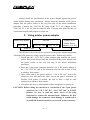
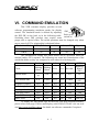
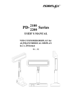
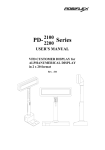
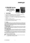
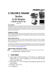
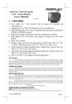
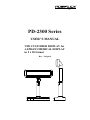
2100 PD-2300 Series 2200 USER’S MANUAL VFD CUSTOMER DISPLAY for ALPHANUMERICAL DISPLAY in 2 x 20 format Rev. : Original SOME IMPORTANT NOTES FCC NOTICE This equipment generates, uses, and can radiate radio frequency energy and, if not installed and used in accordance with the instructions manual, may cause interference to radio communications. It has been tested and found to comply with limits for a Class A digital device pursuant to subpart J of Part 15 of FCC Rules, which are designed to provide reasonable protection against interference when operated in a commercial environment. Operation of this equipment in a residential area is likely to cause interference in which case the user at his own expense will be required to take whatever measures to correct the interference. WARRANTY LIMITS Warranty will terminate automatically when the machine is opened by any person other than the authorized technicians. The user should consult his/her dealer for the problem happened. Warranty voids if the user does not follow the instructions in application of this merchandise. The manufacturer is by no means responsible for any damage or hazard caused by improper application. ABOUT THIS MANUAL This manual assists the user to utilize the VFD customer display PD-2300 series. This series provides versatile fonts and support various instruction sets. This series of products receive instructions in serial communication protocols and is capable of entering pass through mode so that all instructions received pass on to next connected serial device if properly configured. The manufacturer of the PD-2300 series heartily apologizes to the user for reserving the right to change or to modify this manual without notice due to the rapid and constant progress and improvement on science and technology. The user who wants to construct software program to control this product may always obtain the most up to date information through any of our web sites: http://www.posiflex.com, http://www.posiflex.com.tw or http://www.posiflexusa.com. Copyright Posiflex Inc. 2004 TRADE MARKS AND SERVICE MARKS POSIFLEX is a registered trademark of Posiflex Incorporated. Other brand and product names are trademarks and registered trademarks and service marks of their respective owners. P/N: 19470900010 TABLE OF CONTENTS FEATURES ························ 1 Brief · · · · · · · · · · · · · · · · · · · · · · · · · · · · · 1 Detail · · · · · · · · · · · · · · · · · · · · · · · · · · · · · 1 - 1 - 1 - 1 MODEL NUMBERS · · · · · · · · · · · · · · · · · · 2 CARTON CONTENTS · · · · · · · · · · · · · · · · 3 INSTALLATION · · · · · · · · · · · · · · · · · · · · 4 - 1 Connector area · · · · · · · · · · · · · · · · · · · · · · · · 4 Signal connection · · · · · · · · · · · · · · · · · · · · · · · 4 For RS232 interface stand alone models · · · · · · · · · · · 4 For USB interface models · · · · · · · · · · · · · · · · · 4 For PST option · · · · · · · · · · · · · · · · · · · · · · 4 Power connection · · · · · · · · · · · · · · · · · · · · · · · 4 Using 12 V AC power adaptor · · · · · · · · · · · · · · · 4 Using printer power adaptor · · · · · · · · · · · · · · · · 4 After powering up · · · · · · · · · · · · · · · · · · · · · · 4 MECHANICAL FEATURES · · · · · · · · · · · · 5 Dimension drawing · · · · · · · · · · · · · · · · · · · · · · 5 Display frame features · · · · · · · · · · · · · · · · · · · · 5 COMMAND EMULATION · · · · · · · · · · · · · 6 SPECIFICATIONS · · · · · · · · · · · · · · · · · · · 7 Optical · · · · · · · · · · · · · · · · · · · · · · · · · · · · 7 Mechanical · · · · · · · · · · · · · · · · · · · · · · · · · · 7 Electrical · · · · · · · · · · · · · · · · · · · · · · · · · · · 7 Environmental · · · · · · · · · · · · · · · · · · · · · · · · 7 i - 1 - 1 1 1 1 1 2 2 2 2 3 - 1 - 1 - 1 - 1 - 1 1 1 1 1 I. FEATURES A. Brief PD-2300 series is a product series of customer display utilizing VFD (vacuum fluorescent display) technology with adequately large character size. This series presents not only exactly same mechanical styling and all functional capabilities as its predecessor PD-2200 series but also additional advanced arrangement for power connection and interface selection of USB. B. Detail • • • • • • • • • • • • • • Bright vacuum fluorescent display Two-line display with 20 characters per line Adequately large characters for easy viewing (9.03 mm by 5.25 mm) Long life and trouble free operation Generous base best for freely stand alone Two adjustable viewing angles Pole height adjustable Display frame can slide horizontally and rotate 360° freely Brightness adjustable by software Simple installation Direct interface connection with computers and peripherals Selectable interface of Serial interface with pass through capability and USB interface Multiple choices for power supply source. Support Euro Code Page 1-1 II. MODEL NUMBERS Example: PD2300SUS-B -B: Beige case, green display -C: Charcoal case, blue display Product type for VFD customer display of 9 mm letter height Reserved digit 0: stand alone model 1: PST option (RS232 interface only, power source not required) 00: No adaptor , no power cable AU: Australia 12 V AC adaptor CN: China 12 V AC adaptor EU: Europe 12 V AC adaptor SA: South Africa 12 V AC adaptor UK: British12 V AC adaptor US: USA 12 V AC adaptor PP: power cable (using printer power) S: RS232 interface U: USB interface 2-1 III. CARTON CONTENTS 1. 2. 3. 4. Pole display, pre-assembled. User’s Manual. Interface cable (RS232 or USB per order) 12 V AC power adaptor or power cable for printer power or neither per order 3-1 IV. INSTALLATION A. Connector area In base of stand alone models, looking from rear side of the bottom, the connector area will look like below: For serial (RS232) interface models: RS232 Out RS232 In VFD +24 V DC In +24 V DC Out 12 V AC In For USB interface models: USB B. Signal connection 1. For RS232 interface stand alone models POS printer RS232 PD2300 RS232 Out RS232 In HOST COM port 1. With all power off, connect the male connector of interface cable to “RS232 In” in connector area and the female end to COM port of the host. 4-1 2. Connect the pass through RS232 device to the “RS232 Out” if exists. 3. Proceed connection to power adaptor of either 12 V AC or +24 V DC. 2. For USB interface models PD2300 HOST USB USB 1. Connect the “B” type connector of the interface cable to “USB” in connector area and the “A” type end to USB port of the host. 2. Proceed connection to power adaptor of either 12 V AC or +24 V DC. 3. For PST option PST PD2301 VFD Follow the pole display installation instruction of the PST series. No external power connection beyond the power arrangement in COM port of PST system is required. C. Power connection 1. Using 12 V AC power adaptor PD2300 12 V AC Power Adaptor 12 V AC In 4-2 Always check the specification of the power adaptor against the power socket before making any connection. Always keep the insertion of the power adaptor into the power socket as the very last step of the whole installation procedure. Connect the 2.5φ/5.5φ DC plug of the 12 V AC adapter to the 2.5φ/5.5φ “12 V AC In” jack in connector area. You may now place the base on a horizontal surface and prepare to power on. 2. Using printer power adaptor Posiflex POS printer +24 V DC PD2300 +24 V DC Out +24 V DC In Posiflex POS Printer Power Adaptor (24 V DC) Power Cable The PD2300 series can also be powered by the power adaptor supporting a Posiflex POS printer by using a specific power cable. Follow steps below: 1. Check that the (+24 V DC) power adaptor plug matches the power socket. But please always keep the insertion of the power adaptor into the power socket as the very last step of the whole installation procedure. 2. Insert the 3 pin power connector from the +24 V DC power adaptor to the “+24 V DC In” jack in the connector area. Be sure to hear a click to obtain a firm contact. 3. Insert either end of the power cable to “+24 V DC Out” jack in the connector area and insert the other end to the power connector of Posiflex POS printer if needed. Be sure to hear a click at each connection to obtain a firm contact. 4. Now place the base on a horizontal surface and prepare to power on. CAUTION: Before doing the insertion or extraction of the 3 pin power connector (at “+24 V DC In”, “+24 V DC Out” or in POS printer), be sure to pull the outer sleeve of the plug backward to release the internal latch. Failure to do this could damage the connector. Such damage is considered as an artificial destruction and is not covered by the warranty. 4-3 D. After powering up A firmware version and emulation mode as power on sign will appear for a while. Then a blinking block-shaped cursor will appear at the left-most digit of the top row for Noritake or Futaba emulation mode and no cursor will appear for other emulation modes. The installation is now completed. 4-4 V. MECHANICAL FEATURES A. Dimension drawing 70.0 260.0 157.1 60.3 36.8 70.0 70.0 22.970.0 135.0 315.0 180.0 135.0 Stroke 180.0 (Lowest height) 41.0 41.0 220.0 (Max. height) 41.0 110.0 PD2300 Series B. Display frame features In addition to the above drawings given, the PD2300 series is delicately designed to have the following user-friendly mechanical features for most up-todate store management systems. Button switch The display panel of PD2300 series can be moved or rotated/tilted both vertically and horizontally The overall pole height can be adjusted freely by pulling the button switch and match it to one of the concave cavities on inner pole at a proper height. Overall height of PD2300 series is adjustable from 291mm to 426mm. 5-1 The display frame can be slid left-and-right-wise for a total sliding distance of 100mm. It can also be rotated horizontally for almost 360 degree, however, the rotation is limited to within 360 degree to avoid the internal cable to be broken. It can further be tilted to offer 2 different viewing angles ---14.5°, 30° from the vertical position. 5-2 VI. COMMAND EMULATION This VFD customer display provides several software programming emulation modes for display control. The emulation mode is defined by adjusting SW1 the DIP SW on the back as in the following table. Push up to switch on SW2 Switching these DIP switches may require some proper tool or special effort. The switch positions must be changed only when power turned off. The relationship is tabulated below. UTC (/Futaba) Noritake Aedex (/ADM) Epson Emulation Mode on off on off SW 1 on on off off SW 2 The parenthesized Futaba and ADM modes can be accessible when the internal jumper JP3 is opened. The followings are some brief introduction of the emulation modes as they are compared to each other for selection guide : Mode Futaba Noritake Aedex ADM Epson Cursor Blinking Blinking Block Block N.A. N.A. Invisible Default mode V. scroll up Ovr N.A. N.A. Ovr User defined font N.A. 2 chars N.A. N.A. 2 chars Brightness control Pass through function Leading code change Code page select Auto scroll message Timer clock YES YES YES YES YES NO YES YES YES YES YES NO NO YES YES NO NO NO NO NO NO NO NO NO YES YES NO YES NO YES UTC Blinking Block (DP) PT 2 chars (PT) YES (DP) YES (PT) YES (PT) YES YES (PT) YES (PT) To display the Euro-dollar sign on the Euro code page supported models, please select code page 13(Hex) and display code D5(Hex). Please visit our web site http://www.posiflex.com.tw for details on software commands if required. 6-1 VII. SPECIFICATIONS A. Optical Number of digits Dot matrix Digit height Digit width Display color 20 digits/row, 2 rows 5 X 7 dots 9.03 mm 5.25 mm Blue or Green B. Mechanical Weight Height Width Depth Case color 0.7 kg (1.5 lbs) 291 ~ 426 mm 260 mm 110 mm Charcoal or Beige C. Electrical 12 V AC power adapter Input: 120VAC, 60 Hz or 220VAC, 50 Hz Output: 12VAC heavy duty, 1.2 A (min.) +24 V DC power adaptor : Input: 120VAC~ 220VAC, 50~60 Hz Output: 24VDC heavy duty, 2.5 A Power from Posiflex POS system: + 5VDC (PD2301) D. Environmental Operating temperature Storage temperature Relative humidity Vibration Shock 0° to + 40°C -20° to + 70°C 90%, non-condensing 4G 40 G WARNING: If the user opens the pole display housing to make any change, all the product warranty will be voided. 7-1