1
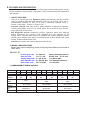
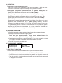
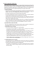
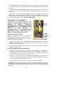
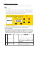
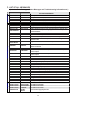
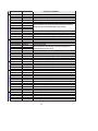
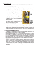
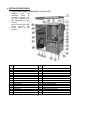
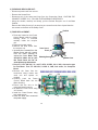
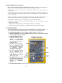
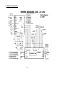
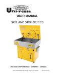
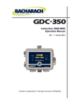
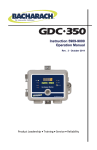
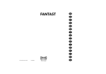
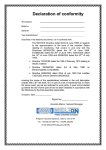
USER MANUAL 34S SERIES RECYCLING PARTS WASHERS UNI-RAM CORPORATION • ONTARIO • CANADA NOTE: APPEARANCE MAY NOT BE EXACTLY AS SHOWN Revision 2014-08-22 CONTENTS A. INTRODUCTION ………………………………… 3 B. FEATURES AND PREPARATION 1) SAFETY FEATURES 2) MODEL CODE STRUCTURE 3) COMPARISON OF SPECIFICATIONS 4) DEFINITIONS 5) RECEIVING INSPECTION 6) ACCESSORY KIT CONTENTS 7) SELECTION OF LOCATION 8) CONSTRUCTION AND PART NAME ………………………………… ………………………………… ………………………………… ………………………………… ………………………………… ………………………………… ………………………………… ………………………………… ………………………………… 4 4 4 4 5 5 5 5 6 C. SETUP AND CONNECTIONS ………………………………… 1) THE AIR SUPPLY CONNECTION ………………………………… 2) LOCATION AND ELECTRIC CONNECTION ………………………………… 3) SOLVENT REQUIREMENTS ………………………………… 4) INITIAL SETUP (PREPARATION FOR PARTS CLEANING) ….……………. 5) TOPPING OF THE CLEAN SOLVENT TANK …………………………………. 7 7 7 8 8 9 D. PARTS WASHER OPERATION ………………………………… 1) PARTS CLEANING ………………………………… 2) SOLVENT RECYCLING FUNCTION ………………………………… 3) RESIDUE VISCOSITY CHECK ………………………………… 4) DUTY TANK MANUAL DRAIN PROCEDURE ………………………………… 10 10 10 11 11 E. CONTROL PANEL PROCEDURES 1) DIGITAL DISPLAY 2) OPERATING PARAMETERS 3) USER SETUP MODE 4) HOW TO ACCESS DIFFERENT MODES 5) USER SEUP MODEL 6) TEST MODE 7) CLEANING MODE 8) MANUAL MODE ………………………………… ………………………………… ………………………………… ………………………………… ………………………………… ………………………………… ………………………………… ………………………………… ………………………………… 12 12 12 12 13 14 14 14 14 F. LIST OF ALL MESSAGES ………………………………… 15 G. MAINTENANCE 1) DUTY TANK MAINTENANCE 2) CLEANING THE CONDENSER 3) DISTILLATION TANK MAINTENANCE 4) OTHER REGULAR MAINTENANCE …………………………………. 17 …………………………………. 17 …………………………………. 17 …………………………………. 17 …………………………………. 17 H. SERVICE PROCEDURES …………………………………. 1) STRUCTURE AND KEY COMPONENTS OF RECYCLER ………………... 2) REMOVING RECYCLER UNIT ………………………………….. 3) FUSE REPLACEMENT ………………………………….. 4) REPLACEMENT OF LID GASKET ………………………………….. 5) CONNECTION BOX ………………………………….. 6) LIST OF REPLACEMENT PARTS ………………………………….. 18 18 19 19 20 20 21 I. 22 WIRING DIAGRAM J. FULL PRODCUTS WARRANTY …………………………………. ………………………………….. 23 K. CUSTOMER / WARRANTY INFORMATION SHEET 2 A. INTRODUCTION Thank you for purchasing Uni-ram 34S Series Recycling Part Washer. Every machine has been fully tested for compliance with Quality Assurance Standards. This model is certified under UL and CSA standards for use in hazardous locations, Class 1, Division I and II as well as for non-classified location. Follow the instructions on preparation, operation and maintenance to operate this machine safely and effectively. Ensure that this manual is readily available to the operator at all times. Uni-ram holds many patents on designs used in its innovative products. If you have any questions about the operation of this machine, contact: North America: Uni-ram Technical Service 1-800-417- 9133 Other Continents: Contact Your Supplier CAUTIONS AND WARNINGS The operator should wear protective clothing in accordance with local safety and environmental regulations, with a minimum of face goggles and gloves along with an apron and respirator if required. Always turn off the power supply before performing maintenance. DO NOT SMOKE OR USE THIS EQUIPMENT NEAR A POTENTIAL SOURCE OF IGNITION SUCH AS SPARKS OR AN OPEN FLAME. This unit must be located at least 1.8 meters (6 feet) from all potential sources of ignition including electrical receptacles, switches, pilot lights, fixtures and contacts when installed in a non hazardous locations. To enhance the safety, locate the electric connection box or receptacles at least 50cm (18 inches) above floor level and as far from the unit as the length of power cord allows. The ambient temperature must be between 5°C (41°F) to 35°C (95°F). DO NOT RECYCLE NITROCELLULOSE WHICH IS EXTREMELY VOLATILE. IT AUTOMATICALLY IGNITES AT 135°C TO 166°C (275°F TO 330°F). Do not install, operate or maintain this equipment where the auto ignition temperature of the hazardous atmosphere(s) is lower than 260°C (500°F). This equipment is designed to be used with combustible solvent. Do not use flammable or explosive solvents in this equipment. This equipment must be connected to a suitable electric supply source by a qualified electrician and according to applicable laws and regulations. 3 B. FEATURES AND PREPARATION Solvent Recycler built into this unit features oil-free direct electric heating system and aircooled condenser, which provides a rapid-start, a short cool-down time and maintenance free operation. 1 ) SAFETY FEATURES: This unit is constructed to be Explosion proof and intrinsically safe and certified under UL standard 2208 and CSA standards C22.2 No. 30 and No. 88 for use in non-hazardous locations as well as for use in hazardous locations Class 1, Division 1 and Class 1, Division 2, Group D-T2C. • Computer controls, with many built-in safety programs, all aspects of operation including temperature control of all critical points like distillation tank, solvent vapor passage and fan motor. • Self Diagnostic system constantly monitors operation status and displays status throughout the process. Error messages are also displayed on the Display Panel. Computer also monitors air pressure and vacuum pressure (Vacuum version only) in addition to the level in all containers such as Duty Solvent Tank, Clean Solvent Tank and Waste Debris Tank. • Dual lid cover system with a built-in pressure relief function. • 2 ) MODEL CODE STRUCTURE: Model Codes used for designating models of Recycling Parts Washer are structured as shown below; 34 S L P– 37 Process type code Sink size code Voltage range code Sink material Code Base model code P = Vacuum, (None) = Atmospheric pressure 37 = 37” wide, 42 = 42” wide, 55 = 55” wide L = 100v to 120v, H = 200v to 240v S = Stainless Steel, G = Painted galvanized steel 34 = 34 series, 23 = 23 series 3 ) COMPARISON OF SPECIFICATIONS: MODEL 34SL-37 34SLP-37 34SH-37 34SHP-37 34SL-42 34SLP-42 34SH-42 34SHP-42 34SL-55 34SLP-55 34SH-55 34SHP VACUUM PROC No Yes No Yes No Yes No Yes No Yes No Yes VOLTAGE (V) 100-120V 200-240V 100-120V 200-240V 100-120V 200-240V RECOMMENDE 20A 10A 20A 10A 20A 10A D CIRCUIT MAX. SET240°C 240°C 240°C POINT SINK SIZE (W x D x SHIP DIM (W x D x H) WEIGHT 37 x 28 x 8 in 94 x 71 x 20 cm 102 x 122 x 127 cm 40 x 48 x 50 in 190 kg (420 lb) 42 x 30 x 8 in 107 x 76 x 20 cm 102 x 122 x 127 cm 40 x 48 x 50 in 205 kg (450 lb) 4 55 x 30 x 8 in 140 x 76 x 20 cm 102 x 158 x 127 cm 40 x 62 x 50 in 220 kg (480 lb) 4 ) DEFINITIONS: Flash Point or Flash Point Temperature. Flash Point or Flash Point Temperature is the lowest temperature at which the vapor of a solvent can be made to ignite momentarily in air by a source of ignition. Auto-ignition Temperature (often referred to as “Ignition Temperature” or “Ignition Point”): The temperature at which solvent ignites by itself. The lowest ignition point of the solvent to be used in this unit is 260ºC (500ºF) . Boiling Point Temperature: (often referred to as “Boiling Point” or “B.P.”) The temperature at which solvent starts boiling and turns into solvent vapor. The highest boiling point of the solvent to be used in this unit is about 220ºC (428ºF). Set-point Temperature. The temperature selected by operator through Set-up Manu of the software. For most applications, this temperature is set to 240ºC (464ºF). Generally Set-Point temperature should be set to about 20ºC (68ºF) to 40ºC (104ºF) degrees higher than the highest boiling point of the solvents. Contaminants like oil and grease that go into the cleaning solvent during the cleaning operation are known to raise the boiling point depending on the extent of contamination. The vacuum version of 34SL may be considered if BP of the solvent is higher than 200ºC (392ºF). 5 ) RECEIVING INSPECTION: Carefully inspect the shipping crate and carton for any sign of transport damage. Carefully remove the unit from the shipping pallet. Check the unit for damage. Report any transport damage immediately to the carrier and your supplier. Initiate a freight claim with the carrier. The manufacturer is not responsible for freight damage. Check the Accessory Kit for the parts listed below. If any parts are missing, contact your supplier. Additional consumables and accessories are also listed. Level the unit using the adjustable feet. 6 ) ACCESSORY KIT CONTENTS: Manual, ENGLISH Lid Gasket (Spare) MNL-34SE Viton 974-2150V 7 ) SELECTION OF LOCATION: Select a location that meets EACH AND EVERY requirement described below. Comply with the instructions in the section: CAUTIONS AND WARNINGS. Position this unit in a location so that there is at least 15 cm (6 inches) of space all around the unit. Ensure that the sink lid and front access door freely opens fully The unit must be in a location where people traffic cannot interfere with power cord, air supply line or connection. 5 8 ) CONSTRUCTION AND PART NAME: SINK LID FLO-THROU BRUSH LID STAY (HEAT SENSITIVE) FLOW CONTROL VALVES FLEXIBLE SPIGOT STAINLESS STEEL SINK WASH TIMER (15 MIN.) COMPUTER BOX CONTROL PANEL SOLVENT RECYCLER (REMOVABLE) ACCESS DOOR LOCK VACUUM GAGE ADJUSTABLE LEGS WASTE CONARTMENT DOOR FRONT ACCESS FOOT PEDAL CLEAN TANK LEVEL GAGE VIEW WITH FRONT ACCESS DOOR REMOVED Duty Solvent Tank Clean Tank Door Clean Solvent Tank Waste Residue Tank Duty Tank Drain Valve 6 C. SETUP AND CONNECTIONS Note: the unit is designed to become inoperable if certain setup procedures are not followed. 1) THE AIR SUPPLY CONNECTION: This unit is equipped with air operated components including 3 Dual Diaphragm pumps, 4 solenoid valves and a pneumatic drain ball valve. These components require a supply of clean, dry air. If necessary, a Moisture Filter must be installed (not included). An air supply of at least 85 PSI (6 kg/cm2) and 115 L/MIN is required for proper functioning. WARNING: A PRESSURE REGULATOR IS PRE-INSTALLED. BYPASSING OR REMOVING THE REGULATOR COULD RESULT IN THE USE OF AIR PRESSURE HIGHER THAN 85 PSI (6 KG/CM2). THIS COULD DAMAGE THE PUMPS AND VOID THE WARRANTY. Apply Teflon tape to the Air Inlet Fitting (1/4” NPT Female Threads) and connect the Moisture Filter to it. Connect the air supply to the Filter. Make sure that there are no leakages at the connections. Also make sure that the air is free of dust, rust and other contaminants. Drain the Moisture Filter before each recy- cling. 2 ) LOCATION AND ELECTRIC CONNECTION: This unit is certified by ETL for use in non-hazardous locations and hazardous locations Class 1, Division 1 Group D and Class 1, Division 2, Group D. Although the most installation locations are non-hazardous locations, careful attention is needed to comply with all local legal and regulatory requirements. Non-hazardous Location: In most cases that the cleaning solution used is non-flammable solvent and a nonhazardous location may be chosen for installation. In this case, a regular (nonexplosion proof) electric plug may be used. To ensure safety, we recommend that you use a receptacle located a minimum of 6 feet (185 cm) from the unit and a minimum of 80 cm (30”) high from the floor. We also recommend that the unit be located at least 6 feet from any potential source of ignition such as electrical receptacles, switches, pilot lights, electrical fixtures, contacts and similar equipment. To clarify the definition of an appropriate location, contact your local authority. This unit must be connected to the power supply only by a qualified electrician in accordance with the National Electrical Code and any other local regulations. The use of dedicated power supply is strongly recommended to avoid interference from other equipment sharing same power supply. Hazardous Location: If hazardous location (Class 1, Division 1, Group D and Class 1, Division 2, Group D) was chosen for installing this unit, the power cord must be connected to the main power supply either by means of certified explosion proof plug and receptacles or by hard wiring, only by a qualified electrician, in accordance with the National Electrical Code and any other local regulations. Whether by explosion-proof plug and receptacles or hard wired, the dedicated power supply is strongly recommended to avoid interference from other equipment sharing same power supply. 7 a.) The power cord must be connected directly to the main power supply according to the instructions in this section and elsewhere in this manual. No extension cord must be used. b.) Connect the unit to a dedicated branch circuit using one of the methods described in the Location section. Make sure the correct voltage and amperage are supplied to the unit. Refer to the table on page 4. On first power up the Display Panel shows “NEW UNIT SET-UP”. After supplying the new solvent to the unit and when the unit is ready to begin a new cycle, the Display Panel shows: READY SP =240°C START IN 2H OM Note: changes to the unit’s operating parameters should only be made when the unit is in this “READY” mode (see OPERATION section), (SP = Set Point) 3 ) SOLVENT REQUIREMENTS: Initial filling of cleaning solvent for this unit requires two 5 gallon pails (20 litre pails) of cleaning solvent. Solvent to be used for cleaning operation by this unit must meet each requirement described below. Be sure to read the MSDS (Material Solvent Data Sheet) on the properties of the pure solvent to be recycled. The BP (Boiling Point) of the dirty solvent must be less than 220°C (428°F) and the Auto-ignition point must be higher than 260°C (500°F). Note; BP increases with greater contamination. The flash point of the solvent to be used must be higher than 40°C (105°F) and lower than 66°C (150°F). Select the cleaning solvent which does not have harmful ingredient, poor cleaning power, unpleasant odor, skin irritation, high evaporation rate, etc. 4 ) INITIAL SETUP (PREPARATION FOR PARTS CLEANING) • Remove the front door and notice the location of the Duty Tank and the Clean Tank (see page 7). • THE DISPLAY PANEL SHOULD BE READING “NEW UNIT SET-UP” (At the FIRST POWER UP only). • Press “START” button. The display will show “FILL DUTY TANK” and the Green Power LED will start flashing and a beeping sound will start. • Open the Sink Lid fully and fill the Duty Tank by slowly pouring clean solvent directly into the drain hole at the bottom of the Wash Sink. Five Gal (19L) of solvent is required. The beeping sound and flashing of the Green LED will continue until enough solvent has been added. Then the sound and the flashing will stop and the Display will read “DUTY TANK FULL”. • After a 10 second delay, the beeping sound and the flashing of the Green LED will start again and the Display will read “FILL CLEAN TANK”. • Open the hinged lid of the Clean Tank and slowly and carefully pour clean solvent into the tank until the beeping stops - approximately 5 Gal (19L) is required. The Display will then read “CLEAN TANK FULL” and the liquid level showing in the sight gage should be close to the line (“5 Gallon - 19 Litres”). The beeping sound and the flashing of the Green LED will also stop. • After about 10 seconds, the Display will change to: “READY SP =240°C” in the first line 8 and ”START IN 2H OM” in the 2nd line. This means that the unit is ready for use and recycling of contaminated solvent will automatically start after two hours of accumulated cleaning operation time (which is initially set to 2 hours). This “AUTO START” time period is recorded by the computer and is the amount of cleaning time used by an operator as measured by an air sensor attached to the Wash Pump line. This setting of AUTO-START time is adjustable by user menu as explained in SETUP MODE section on page 10. Decrease the time if exceptionally dirty parts need to be cleaned or increase to accommodate light-duty cleaning. • From READY mode or STAND-BY mode, recycling may be started manually at any time by pressing the START button. This will over-ride the “AUTO START” setting only for this cycle. • If “AUTO START” time is set to ZERO “0” hour, the unit can only be started by pressing the START button. CAUTION: Although changes to some of the unit’s operating parameters can be made at any time by pressing “STOP” and entering SETUP MODE, such changes could cause serious problems if done in the middle of a recycling operation. Therefore, it is highly recommended that such changes only be made when the unit is in “READY” mode (ie: just before or just after a recycling operation). 5 ) TOPPING OF THE CLEAN SOLVENT TANK: From time to time, it becomes necessary to add solvent to the CLEAN SOLVENT TANK because of loss by evaporation, drag-off and waste removal. When the lower level sensor in the CLEAN SOLVENT TANK detects the low solvent level, the Display will read “FILL CLEAN TANK”, an alarm will sound and the Green Power LED will start flashing. Add solvent to the Clean Solvent Tank as follows: Make sure that unit is in READY mode - the display will read “READY SP =240°C” and the Green Power LED will NOT be flashing. By pulling the Unlock Handle, remove the Access Door. Open the hinged lid of the Clean Tank and slowly, carefully pour clean solvent into the tank until the alarm and the flashing Green LED stop - approximately 2-3 Gal (812 Litres) of clean solvent are required. The Display will then read “CLEAN TANK FULL” and the liquid level showing in the sight gage should be close to the line (“5 Gallon - 19 Litres”). CAUTION: Do Not add more than 2-3 GAL (8-12 LITRES) to the CLEAN SOLVENT TANK, or it may overflow during NIGHT MODE. 9 D. PARTS WASHER OPERATION After the INITIAL SETUP, the unit is ready for parts cleaning and automatic recycling. The AUTO START function will start the recycling operation after a pre-set amount of cleaning time (the factory setting is 2 hours). This setting can be changed or AUTO START can be disabled and changed to Manual Start in SETUP MODE. The Set Point Temperature and Drain Temperature can also be adjusted depending on the type of solvent used. 1 ) PARTS CLEANING: • The amount of solvent used for parts cleaning is controlled fi rst by the Solvent Control Valves, one for the Flow-through Brush and the other for the Spigot. Using the handles, each valve can be independently turned fully or partially open. • For precise, hands free control of solvent, press the foot pedal. • For a timer-controlled flow of solvent, turn the timer knob. The fl ow duration depends on how far the timer knob is turned - the range is 0 to 15 minutes. • A Strainer Disc and Filter Basket located at the bottom of the Wash Sink collect most of the solids in the dirty solvent; the rest goes through the sink’s drain into the “DUTY TANK” which is located under the sink. • A Three Stage filtering system protects the Duty Tank: 1) a Strainer Disc (perforated disk); 2) a removable, fine-mesh Filter Basket and 3) another Screen inside the top of the Duty Tank. The filters should all be checked daily and cleaned if necessary. 2 ) SOLVENT RECYCLING FUNCTION: This unit is equipped with a built-in solvent recycler which is capable of recycling the contaminated solvent during the working day as well as after hours. a.) DAY MODE solvent recycling: The recycling during the working day is called Day Mode. • The purpose of the Day Mode is to maintain solvent in relatively clean conditions throughout the working day for utmost cleaning efficiency. • Day Mode is automatically started after cleaning operation accumulates to the preset number of hours. Only the time period the wash pump is in use in counted. • to Wash Sink is counted as the cleaning operation time. Therefore, the factory default setting of 2 hours would cover much longer cleaning period in general. • This Day Mode may also be started manually by pressing START button when display shows READY and Auto-start function is over-ridden for this cycle only. • The Day Mode function is independent of the Parts Washer part of the unit and would not interfere with cleaning operation. b.) AFTER HOURS solvent recycling: The recycling after hours is called Night Mode, which may be started only by pressing the START button continuously for more than 3 seconds. Three short beeps and one long beep will be heard before starting the Night Mode. • The purpose of the Night Mode is to recycle all contaminated solvent completely during the nigh so that the cleaning operation can be started with clean solvent in the next morning. 10 • The Night Mode function is designed to remove all contaminated solvent from Duty Tank and therefore no cleaning operation is recommended during the Night Mode recycling. • The Duty Tank is completely emptied, rinsed with a small amount of clean solvent and then filled up with clean solvent during the Night Mode to be ready next morning.. • If the recycler is still in Day Mode operation at the end of working day, presses STOP button. After display returns to READY mode, press START button for more than 3 seconds. Two short beeps and a longer beep will sound to confirm the start of Night Mode with LCD showing AFTER HOURS MODE. IMPORTANT DAILY MAITNTENANCE: TO PREVENT AN OVERFLOW OF OILY RESIDUE, CHECK RESIDUE CONTAINER AND DISPOSE OF RESIDUE REGULARLY ACCORDING TO LOCAL REGULATIONS. IN ADDITION, CHECK IF THE RESIDUE IS THIN ENOUGH TO DRAIN PROPERLY BY FOLLOWING STEP 1 OF THE MANUAL DRAIN PROCEDURE BELOW. COMPLETE STEPS 2 AND 3 IF THE RESIDUE IS TOO THICK. DUTY TANK DRAIN VALVE RESIDUE TRAY 3 ) RESIDUE VISCOSITY CHECK: During the recycling process, the residue is automatically drained into the residue container. If the residue is too thick (viscous), it may not drain properly. There are two solutions: VIEW WITH ACCESS DOOR REMOVED. Increase the Residue Drain Temperature in the SETUP program (see SETUP MODE section). Keep in mind that the odor of the residue will increase as the Residue Temperature increases. Perform a DUTY TANK MANUAL DRAIN of the thick residue using the Manual Mode procedures below. 4 ) DUTY TANK MANUAL DRAIN PROCEDURE: First check to make sure that the residue is thick enough to require manual draining by moving the Drain Valve Lever to the OPEN position (vertical) for 1 second and then closing it. If thin liquid comes out in significant quantities, the residue is thin and manual draining is not required. If little or no residue comes out, the residue is probably thick and needs to be loosened up and partially drained. Push and hold the black button for 3 seconds. This sends air through the residue to loosen it. Close the valve as soon as the residue becomes thin and free fl owing. CAUTION: This procedure is intended to remove the very thick material in the residue only and should NOT be used to drain the thin (non-viscous) residue from the Duty Tank. Draining all of the residue through the Manual Drain will overflow the residue container. 11 E. CONTROL PANEL PROCEDURES Control panel (Keypad) is located on the Computer Box attached to the recycler unit and used to control all user-accessible functions. Keep Keypad free of paint, solvent, dirt etc. To prevent damage to the Keypad, do not use tools or other hard objects to push the buttons. 1 ) DIGITAL DISPLAY: LCD displays 32-characters in 2 lines. Various messages are displayed regarding the status of the operation including temperatures, set points, current cycle stages etc. Error messages that can be used to troubleshoot a problem are also displayed here. To change the temperature units (°C vs °F), press and hold the “+” and “-” buttons until the display switches to the other units (about 2 seconds). READY S.P.=240ºC START IN 2H 0M 34SL-37P 2 ) OPERATING PARAMETERS: The computer is pre-set at the factory for average conditions of use. To change the SET POINT, AUTO START or DRAIN TEMP, enter USER SETUP MODE. 3 ) USER SETUP MODE: We recommend that only personnel with expert understanding of the unit adjust the settings. Adjust set tings only when the display reads: “READY S.P. = xxx°C”. To start SETUP, press and hold SETUP key and press START. Use + or - key to adjust setting. To store the new setting in memory and move to the next parameter, press OK button. STEP 1 2 DISPLAY SET-PT = 240°C KEY TO TO ADJUST ACCEPT + OR - RET. TIME = 1H00M + OO - DESCRIPTION OK The “SET-PT” or SET POINT is the temperature the Distillation Tank will reach to boil the dirty solvent. Lower the Set Point if the Boiling Point of the solvent (as determined from a suitable source such as an MSDS) is less than 240°C. CAUTION: If the SET POINT is too high, the Distillation Tank Lid may leak or blow off. OK Adjustment of refilling time. Default time is set to 1 hour at factory. It is recommended not to change this setting unless advised by a Service Advisor. 12 3 + OR - 4 DRAIN TEMP = 125°C 5 STANDBY SP = 240°C or READY SP Cumulative usage time of parts washer before automatic recycling begins. Default Auto Start Time is set to 2 hours at factory. Adjust to 0 hour if manual start by pressing START button is desired. OK + OR - Default Drain Temperature of Residue is 125°C (257°F); this is adequate for most operations. If there is too much odor during draining, lower the temp; If the waste material is too thick (viscous), increase the drain temperature. Indicates unit is ready and Set Point is set to 240°C OK NA 4 ) HOW TO ACCESS DIFFERENT MODES: The following modes of operation are available for user convenience. NEW UNIT SETUP Mode When the unit is connected to electric power supply for the first time. Display and beeping sound will guide user for the new unit set-up procedures. Refer to 6. Initial Setup on page 6 for details. RECYCLING Mode (= Day Mode) “Day Mode” may be started automatically by pre-set Cleaning Operation Hours (Factory default is 2 hours), or may be started manually by pressing START button. Day Mode may be stopped by pressing STOP button at any time. “ Pressing START button will resume the operation from where it was stopped. Refer to a) Day Mode on page 10 for details. AFTER HOURS Mode (= Night Mode) Night Mode may be started by pressing START button for 3 seconds or longer. Three short beeps followed by a long beep will be heard and Night Mode process will start. Night Mode may be halted by pressing STOP button at any time. this is a temporally stop and pressing START button will resume the operation from where it was stopped. In case of Vacuum version, Vacuum pump will continue to operate in order to prevent a loss of vacuum. To terminate Night Mode completely, press STOP button for 10 seconds, After a long beep, LCD shows PROCESS FULLY TERMINATED for 5 seconds. Transfer pump is then activated to fill up Duty Tank and LCD changes to FILLS DUTY TANK AFTR HOURS HLTD. When Duty Tank is full, it returns to READY mode. Refer to b) After Hours Solvent Recycling on page 11 for details. 13 5 ) USER SETUP Mode: All key parameters are set at the factory to the most suitable values for most operations. However, it may be necessary to change some of the user settable parameters. USER SETUP Mode may be accessed by first holding the SET-UP button and then pressing the START button. The LCD will show SET-UP MODE in the first line. Press the SET-UP button again to make the first adjustment. Refer to USER SET-UP MODE on page 13 for more details. 6 ) TEST Mode: If a malfunction is suspected by the user, TEST Mode is provided to verify some key functions. To access TEST Mode, press and hold the OK button then the Minus (-) button. A series of tests will be conducted automatically. If an error condition occurs, the tests will stop and the display will show the corresponding message. If no error condition occurs, the tests will continue until the end of the test cycle (about 10 minutes). To exit from TEST mode press the STOP button. 7 ) CLEANING Mode: After some use, there may be a build up of debris in the Boiler Tank. CLEANING Mode is available to clear this debris. From READY mode, access Cleaning Mode by pressing and holding the SET-UP button and then the Plus (+) button. The LCD will show CLEANIBG MODE ? indicating CLEANING MODE is in effect. Press OK button to start and follow the instructions displayed for effective cleaning of the Boiler Tank. 8 ) MANUAL Mode: Manual mode is provided within the computer program to enable activation of all solenoid valves manually through Keypad operation. From READY mode, access Manual Mode by pressing and holding the Plus (+) button and then pressing the START Button for 3 seconds. The LCD will show MANUAL ACTIVATE in the 1st line and 1. FILLINP PUMP in the 2nd line. Press START button to activate Solenoid #1. Press Plus (+) button to change. 2. DRAIN CLOSING will show in 2nd line on LCD. Press START button to activate Solenoid #2. Press Plus (+) button to change. 3. DRAIN OPENING will show in 2nd line on LCD. Press START button to activate Solenoid #3. Press Plus (+) button to change. 4. TRANSFER PUMP 1 will show in 2nd line on LCD. Press START button to activate Solenoid #3. Press Plus (+) button to change. Press Plus (+) or Minus (-) buttons to change Solenoid Valves and press STOP button to end Manual Mode. 14 F. LIST OF ALL MESSAGES (includes Error Messages, Status Messages and Troubleshooting Information etc.) Mode New unit set-up LCD DISPLAY 1ST LINE 2ND LINE NEW UNIT SET-UP START TO BEGIN PRIMING: PLEASE FILL DUTY TANK PRIMING: DUTY TANK FULL PRIMING: PLEASE FILL CLEAN TANK PRIMING: CLEAN TANK FULL 34S v7.01 ENGAGING FRESH CYCLE READY S.P.= 240C START IN 2H 0M COND THERMOSTAT LOW AIR PRESSURE AIR PRESSURE OK RECYCLING MODE VACUUM OK HOLD - TOO HOT BOILING TIME-OUT CONDENSER OVER-HEAT Error and status messages CHECK FAN Manual Mode CHECK BOILER TANK SENSOR CHECK CONDENSER SENSOR CHECK BOILER CHECK CLEAN CHECK DUTY CHECK FOR LEAKY SOLVENT LOW TIME-OUT OCCURED WATCHDOG RESET DRAIN FULL TANK RESET OCCURED LO VOLTAGE RESET DISCONNECT ILLEGAL ADDRESS ILLEGAL OPCODE CHECK SUM DEFAULT RESTORED MEMORY FAIL MANUAL ACTIVATE MANUAL ACTIVATE MANUAL ACTIVATE MANUAL ACTIVATE DRAINING HALTED FLOAT SENSOR TANK SENSOR TANK SENSOR DRAIN VALVE FILL CLEAN TANK EMPTY DEBR FRST POWER 1:FILLING PUMP 2:DRAIN CLOSING 3:DRAIN OPENING 4:TRANSFER POSSIBLE OVERFLO EXPLANATION AND REMARKS First set-up of new unit with clean solvent. Fill Dirty Tank with 5 Gallons (20L) of new solvent. Duty Tank is filled with 5 Gallons (20L) of new solvent. Fill Clean Tank with 5 Gallons (20L) of new solvent. Clean Tank is filled with 5 Gallons (20L) of new solvent. Software version shown at power-up of computer. Pressing OK and START starts recycling without recalling memory READY for Day-mode recycling in 2 hours of cleaning operation or awaits key input. Condenser Thermostat is open at the beginning and START is halted. Repair or replace the thermostat. Air pressure is too low and process has been halted. Air pressure is restored and process is resumed.. Vacuum was restored and process resumes. (Vacuum version only.) Filling of Boiler Tank was halted as temperature of Boiler Tank was higher than Ready temperature of 80ºC. Boiling has not been started within time limit and process has been terminated. Condenser Thermo-stat is open indication over-heat. Process is halted. Clean condenser or check Fan. If over-heat lasts more than 10 minutes, the process is halted. Check Thermo-couple wires between computer and Boiler Tank bottom. Repair or replace as required. Check Thermo-couple wires between computer and Condenser Inlet Tube Repair or replace as required. Check Level Sensor Float in Boiler Tank. Check Level Sensor Float in Clean Tank. Check Level Sensor Float in Duty Tank. Drain Valve may be leaking. Repair or replace Drain Valve. Add 2 gallons (8 L) of new solvent to Clean Tank. Recycling was not completed in 5 hours. External power irregularity. Stop and restart. Waste Residue Tank is full. Empty Tank and press START button. (If so equipped.) Process was halted by reset during recycling. Software problem Stop, restart Power board failure. Disconnect power source without delay. Software problem Stop, restart Software problem Stop, restart memory problem Factory default setting was restored. Software problem Stop, restart Press START to activate SL#1 Press START to activate SL#2 Press START to activate SL#3 Press START to activate SL#4 Boiler is full when trying open grain valve. 15 Mode Day Mode Recycling Messages After Hours (Night Mode) Messages User Manu Test Mode Messages Cleaning Mode LCD DISPLAY 1ST LINE 2ND LINE RECYCLING MODE RECYCLING MODE FILL BOILER TANK RECYCLING MODE CLOSE FILL VALVE RECYCLING MODE FILL DUTY TANK RECYCLING MODE HEATER ON RECYCLING MODE TANK =XXXºC RECYCLING MODE VAPOR EX.=XXXºC RECYCLING MODE SET-PT = 240ºC RECYCLING MODE REF.TIME= 1H 30M RECYCLING MODE FILL BOILER TANK RECYCLING MODE DRAIN TEMP=125ºC COOLING T1=XXXºC RECYCLING MODE COOLING T2=XXXºC RECYCLING MODE COOLING T1-xxxºC AFTER HOURS MODE AFTER HOURS MODE FILL BOILER TANK AFTER HOURS MODE HEATER ON AFTER HOURS MODE TANK = xxxºC AFTER HOURS MODE VAPOR EX.=xxxºC AFTER HOURS MODE SET-PT =240ºC AFTER HOURS MODE RINSE DUTY TANK AFTER HOURS MODE FILL DUTY TANK AFTER HOURS MODE COOLING T1-xxxºC AFTER HOURS MODE COOLING T2-xxxºC AFTER HOURS MODE DRAINING DEBRIS COOLING T1=xxxºC SET-UP MODE SET-UP MODE SET-PT =240ºC SET-UP MODE REF.TIME=1H 30M SET-UP MODE AUTO-START=2H SET-UP MODE DRAIN TEMP=125ºC TEST MODE 34S v7.05 T1=xxxºC T2=xxxºC TEST MODE FAN ON TEST MODE BOILER NOT FULL TEST MODE BOILER TANK CLEAN TANK FULL CLEAN TANK NOT FULL TEST MODE I/O TEST TEST MODE KEY SWITCH TEST MODE HEATER TEST CHECK FOR OPEN HEATER LOOP TEST MODE HEATER TEST OK CLEANING MODE DRAIN CLOSED CLEANING MODE FILLING TANK CLEANING MODE HEATER ON CLEANING MODE READY TO CLEAN CLEANING MODE PUSH OK TO CLEANING MODE DRAINING DEBRIS EXPLANATION AND REMARKS Now starting Day-mode recycling. Filling Boiler Tank with dirty solvent from Duty Tank. Closing Valve to fill Boiler Tank. Filling up Duty Tank to full level with clean solvent. Heater has been turned on. Boiler Tank temperature, Vapor temperature Set-point temperature and balance of Refilling Cycles time are displayed alternatively in every 5 seconds Boiler Tank is re-filled during Refill Cycles. Drain temperature is set to 125ºC for 5 seconds.. Boiler temperature is shown while cooling to DRAIN temperature, for 5 seconds Vapor temperature is shown while cooling to DRAIN temperature, for 5 seconds Boiler temperature while cooling to READY temperature. After Hours Mode (Night Mode) recycling is starting. Filling Boiler Tank with dirty solvent from Duty Tank. Heater has been turned on. Boiler Tank temperature, Vapor temperature and Set-point temperature are displayed alternatively in every 5 seconds Duty Tank is rinsed with small amount of clean solvent. Duty Tank is topped-up with solvent from Clean Tank. Shows Boiler temperature while awaiting DRAIN temperature, for 5 seconds. Shows Vapor temperature while awaiting DRAIN temperature, for 5 seconds. Drain Valve is open and draining Debris. Boiler temperature while cooling to READY temperature. User set-up mode. Press SET-UP botany to start 1st menu. Press OK or adjust Set-point temperature (75º-240ºCby 1ºC) Press OK, or adjust Refill Cycle Time as required. Press OK, or adjust Auto. Start Cleaning time as required. Press OK, or adjust Debris Drain temperature as required. Starting test of software version 7.05 Boiler temperature is xxxºC and Vapor temperature is xxxC Fan is on. Feel the wind to confirm. Shows status of Boiler Tank. Display would not ne correct if Boiler Tank level sensor Shows status of Clean Tank. Display would not ne correct if Clean Tank Upper level Testing function of Key Buttons. Do not touch any button. A button is stuck in the pressed position. Repair or replace. Heater is turned on. Heater has open circuit and not working. Repair or replace. Heater is working properly. Starting Cleaning Mode and drain valve is closed. Filling Boiler Tank with 2 L of solvent from Duty Tank. Heater is turned on to warm up solvent to about 60ºC. Solvent reached 60ºC and ready to start cleaning work.. After cleaning, press OK button to drain dirty solvent. Dirty solvent is being drained from Drain Valve 16 G. MAINTENANCE CAUTION: DISCONNECT FROM POWER BEFORE PERFORMING MAINTENANCE 1 ) DUTY TANK MAINTENANCE: In most cleaning operations, the Duty Tank containing contaminated cleaning solvent normally remains reasonably clean and does not require any special maintenance service. This is because, the Duty Tank is completely drained and rinsed before it is filled with clean distilled solvent during the after hours process (= Night Mode). However, the cleaning work involving a lot of sands, soil, clay, etc. and not much oil or grease tends to cause the accumulation of those solid contaminants at the bottom of Duty Tank. The accumulated solid contaminants might disable transfer of contaminated solvent and debris to Distillation Tank. Therefore, such deposit of solid, if happened, must be removed manually during maintenance work. To facilitate such maintenance work, a drain valve and a debris tray are provided below the Duty Tank as shown in photo on the right. DUTY TANK CONNECTION BOX. DRAIN VALVE RESIDUE TRAY 2 ) CLEANING THE CONDENSER: To get access to the condenser, remove the recycler and safety cover (as described above). Clean the condenser using an air pencil. To prevent overheating of the condenser due to the accumulation of dust, the condenser should be vacuumed regularly (every one to three months is recommended depending on usage and operating environment). An overheat situation may cause an error message such as “CONDSR OVER-HEAT” or “CHECK FAN”. 3 ) DISTILLATION TANK MAINTENANCE: To get access to the Distillation Tank, remove the Recycler and Safety Cover (as described above) and then remove the Tank Lid completely. Waste material will eventually build up on the Float Ball, protector plate and the inside surface of the Lid as well as the top sealing surface of the Tank. It is important to keep all of these components clean for proper functioning of the machine. The Float Ball in particular must be keep clean so that it can move freely. A recommended frequency of inspection is one to three months, depending on usage and operating environment. 4 ) OTHER REGULAR MAINTENANCE: Depending on the amount of use and the nature of the material removed during parts washing, it may be- come necessary to remove a buildup of residue from the inside of the Duty Tank. To check this, remove the strainer and Filter Basket from the sink drain and look inside the Duty Tank with a light. If there is material stuck to the bottom of the Tank, the Tank should be disconnected, removed and cleaned. To minimize the work involved this should be done when the Recycler has to be removed for other maintenance. 17 H. SERVICE PROCEDURES 1 ) STRUCTURE AND KEY COMPONENTS OF RECYCLER: Carefully study the illustration below to familiarize yourself with the key components of this equipment and the function. (Note: The view with Side Panel removed. Not exactly same for all models.) ITEM # 1 2 3 4 5 6 7 7A 8 9 10 11 12 13 14 NAME AND DESCRIPTION TOP COVER, R4 BOILER TANK ASSY TANK LID ASSEMBLY, WITH VITON GASKET TANK LID BRACE BAR THUMB SCREW, COMPUTER PROTECTOR BOX COMPUTER BOARD, AC10 VACUUM GAGE (Not shown.) MAIN BODY ASSY, R4 PULL HANDLE RECESSED CONNECTOR BOX UNION NIPPLE HEX. , BRASS DOOR ASSY PULL HANDLE, DOOR BOLT FOOT ITEM # 15 16 17 18 19 20 21 22 22A 23 24 25 26 27 28 18 NAME AND DESCRIPTION DRAIN NIPPLE, 3/4" DRAIN VALVE & ACTUATOR ASSEMBLY AIR PRESSURE REGULATOR, 85PSI (R4) MOTOR HOUSING TUBE ASSY DIAPHRAGM PUMP, BOILER FILLING SEALING FITTING, 1/2’NPTF SOLVENT HOSE, THINNER-RESIST, 3/8ID FAN ASSY., 8”OD PNEUMATIC VALVE ASSEMBLY (Not shown.) CONDENSER ASSEMBLY THERMOSTAT SWITCH THERMO-COUPLE WIRE, VAPOR TUBE TRANSFER TUBE, COPPER ELBOW CONNECTOR, 90D, 1/2T-1/4MP WASTE RESIDUE CONTAINER 2 ) REMOVING RECYCLER UNIT: • Disconnect power cord from source • Remove the Access Door. • Disconnect all of the hoses and lines from the Connection Panel. CAUTION: RECONNECT CORRE- CLY - FOLLOW THE DIAGRAM IF NECESSARY. • Using the Handle, carefully and slowly, pull the Solvent Recycler out of the Base Cabinet. Remove the Safety Cover by fi rst removing one screw from the front clip and then the two screws on the back of the Safety Cover.. Fan Side 3 ) FUSE REPLACEMENT: Fuses are located on the Power Control Board inside the Motor Housing which is mounted vertically inside the recycler unit.. Disconnect power supply. Remove the Side Cover from the recycler unit. Unscrew the 6 screws from the Bottom Cover and pull it gently from the motor housing to expose the fuses. Note: Care should be taken not to pull the Front Cover too far as some wires may disconnect. Motor Housing Power Control Board Mounting Screw Bottom Cover Fuses F1 & F2: 240 VAC, 1A , and F3 & F4: 25 VDC, 2.0 A, 3AG, slow action type for Fan Motor. Fuse F5: 240 VAC, 0.0625 A, 3AG, fast action, for Computer Board. Remove the fuses from the board and, using a meter, test each one and replace as needed. Carefully push the Power Control Board back into the Motor Housing. Ensure that the wire to the computer board is secure. Re-install the Front Cover using all 6 screws.. Install the Guard Screen using two metal screws. Close the Door and re-connect the power supply. F3 F1 19 F4 F2 F5 F6 4 ) REPLACEMENT OF LID GASKET: A worn or damaged Lid Gasket of Distillation Tank of Recycler Unit can cause leakage of solvent and/or solvent vapor. Replace the Gasket by following procedures. D i s c o n n e c t p o w e r c o r d f r o m t h e r ec ep t a c l e. M ak e s u r e t he r e c yc le r i s t ur ne d of f . First R e c yc le r U n it m us t be p u l le d ou t c o m p l e t e l y f r o m Ba s e C a b i n e t o f 3 4 S . D is co n ne c t a l l t ub e s , h o s e s a nd w i r e h a r n es s f r o m t h e c o n n ec t i o n b ox o f r e c y c l er . R e m o v e t h e T op C o v er b y r e m o v i n g a m o un t in g s c r e w f r o m t h e f r o n t o f t he c o v e r a n d t h e n t w o m o u n t i ng s c re w s f r o m t h e b a c k o f t he c o v e r . C a r e f u l ly d i s c o n n e c t t h e Le v e l Se n s or w ir e a t t h e c on n e c t o r . L o o s e n t w o w i ng n u t s f r o m L i d H ol d i n g Ba r a n d th e L id A s sy m ay b e r e m ov ed b y h an d . Remove the Li d Gasket with a small flat-tip screw driver. If necessary. Clean the groove of Lid and fit the new gasket firmly and evenly into the groove. 5 ) CONNECTION BOX: The Connection Box of R4 recycler, which is removably built into the parts washer, is air connections are accommodated within the Connection Box as shown below. Clean Solvent Outlet is used to send the distilled solvent to Clean Tank. Electric Connection is made by DA15S socket containing 12 wires and provided as a part of the main wire harness. Duty Tank Agitation Air is connected to Duty Tank to agitate contaminated solvent in Duty Tank while the solvent is transferred to Distillation Tank. Vacuum Tank Air Supply line is connected to the Diaphragm pump employed to generate vacuum. (Vacuum version only.) Transfer Pump Air Supply line is connected to a diaphragm pump to transfer clean solvent from Clean Tank to Duty Tank. Dirty Solvent Inlet is used to transfer the contaminated solvent from Duty Tank to Recycler for distillation process.. Air Supply Connection is used to supply the regulated air supply to Recycler. 20 All connections are very important for the satisfactory performance of this equipment. Make sure that all connections are made firmly and securely, or leakage and malfunction might result. 6 ) LIST OF REPLACEMENT PARTS: PART NAME FLOW-THROUGH BRUSH AIR BLOW GUN ASSEMBLY FLO-THROUGH SCRAPER TOOL DEBRIS CONTAINER LID SEAL GASKET, NEOPRENE FLEXIBLE SPIGOT FLOW CONTROL BALL VALVE TIMER ASSY, 15 MINUTES POWER BOARD FUSE KIT PART NUMBER 144-399 280-2400 280-2600 3000-9010 300-2150N CALL FOR PART NO. CALL FOR PART NO. CALL FOR PART NO. CALL FOR PART NO. 21 I. WIRING DIAGRAM . v7.05 22 J. Full Product Warranty These Uni-ram products have been engineered and manufactured to high performance standards. Each unit has been subjected to detailed factory testing before shipment. This product comes with a 1-year warranty on parts and labor and a warranty for the 2nd and 3rd years on parts only, excluding in both cases, consumable parts such as the flowthrough brush, flexible spigot, lid gasket and the optional filters. Uni-ram Corporation reserves the right to repair or replace the unit, free of charge, to the original purchaser if a part is found to be defective in material or workmanship as deter- mined by factory service personnel. The items listed below under “Conditions of Warranty” as consumables are not covered. Uni-ram reserves the right to direct the customer to ship the unit collect to the Uni-ram factory or to an approved Service Center for repair using the Uni-ram Return Goods Procedure or to repair the unit on-site. To prevent damage in transport, the purchaser must ship the unit in the original packaging or use alternate adequate packaging. All units must be shipped clean and free of solvent. Conditions of Warranty: As Uni-ram Corporation has no control over the working conditions or circumstances under which the purchaser stores, handles or uses the product, Uni-ram makes no warranty or claim, either expressed or implied with respect to this product’s fitness for any purpose or the result to be obtained from its use. This condition applies to the sale of all products and no representative or distributor of Uni-ram Corporation has the authority to waive or change these conditions. This warranty applies only to the original purchaser and does not apply if the unit has been misused, overloaded, neglected, altered or used for any purpose other than those specified in the operating and installation instructions. Deterioration due to normal wear is not covered by this warranty. Damage due to accident, transportation, fire, floods or acts of God is also not covered. Units whose serial numbers have been altered or removed are not covered. The warranty is invalid if unauthorized abrasives are used in this unit. Unauthorized attempts at self-repair or alterations by the owner also invalidate this warranty. Interior or exterior fishes are not covered by this warranty. Consumable Items are not covered by this warranty. This warranty replaces all other warranties expressed or implied by statute or otherwise. To make a claim, call Uni-ram Service at 1-800-417-9133 in North America or contact your supplier in other countries and quote the serial number of the unit and the date of purchase. SERIAL NUMBER: PURCHASE DATE: PURCHASED FROM: 23 Deleted: - K. CUSTOMER / WARRANTY INFORMATION SHEET This Information Sheet is provided as a tool to provide the Customer, Distributor and the Manufacturer with the necessary information for UNI-RAM Corporation to pro- vide the utmost in customer service and warranty services, if needed. This Information Sheet MUST be filled out completely by the Customer and/or Distributor and sent in to UNI-RAM Corp. upon delivery for unit to be registered and covered under the UNI-RAM Manufacturer’s Warranty Program. THANK YOU CUSTOMER COPY Retain in Owners Manual for Future Reference Customer: Location of Unit: Purchased from: Address: City: City: Model Number of Unit: St: Zip: St: Zip: (34SL-37P, 34SL-42, etc) Serial Number of R4L: (Located inside residue door of R4L) Serial Number of 34S : (Located on right side under sink) / / . Date Purchased: ( Keep this top copy in Owners Manual for future reference) ---------------------------------------------------------------------------------------------------------------(Fill out completely, cut and mail bottom copy to UNI-RAM CORP) MANUFACTURER’S COPY Address: Customer : Purchased From: _ Address: City: St. Zip City: St. Zip: Model Number of Unit: (34SL-37P, 34SL-42,etc) Serial Number of 34S: Date Purchased: Serial Number of R4L: / / Date Delivered: / / Was unit delivered and set properly: Was operation of unit fully explained to you: Comments: For Warranty to become effective in North America, this tear off must be filled out and sent in to: Uni-ram Corporation, 381 Bentley St. Markham, ON. Canada L3R972, Attention: Warranty Registration Dept. OR, in other countries, to your supplier. 24