1
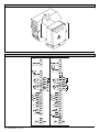
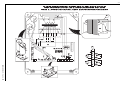
D811184A ver. 04 08-02-02 I CENTRALINA DI COMANDO GB CONTROL UNIT F UNITÉ DE COMMANDE 8 027908 113740 D STEUERZENTRALE E CENTRAL DE MANDO P CENTRAL DO MANDO ARIES - ARIES P ISTRUZIONI D'USO E DI INSTALLAZIONE INSTALLATION AND USER'S MANUAL INSTRUCTIONS D'UTILISATION ET D'INSTALLATION INSTALLATIONS-UND GEBRAUCHSANLEITUNG INSTRUCCIONES DE USO Y DE INSTALACION INSTRUÇÕES DE USO E DE INSTALAÇÃO D811184A_04 ARIES/ARIES-P - Ver. 04 - 3 D811184A_04 ENGLISH USER’S MANUAL Thank you for buying this product, our company is sure that you will be more than satisfied with the product’s performance. The product is supplied with a “WARNINGS” leaflet and an “INSTRUCTION MANUAL”. These should both be read carefully as they provide important information about safety, installation, operation and maintenance. This product complies with the recognised technical standards and safety regulations. We declare that this product is in conformity with the following European Directives: 89/336/EEC and 73/23/EEC (and subsequent amendments). 1) GENERAL OUTLINE The ARIES control unit has been designed for swing gates. It can be used for one or two gate controllers. The control unit mod. ARIES P can also be used to perform opening of a single actuator while keeping the other one closed (pedestrian access). 2) FUNCTIONS STOP: In all cases: it stops the gate until a new start command is given. PHOT: Functions can be set with Dip-Switch. Activated during closing. Activated during opening and closing. Rapid closing ON: When the position of the gate photocells is exceeded, during both opening and closing, the gate automatically starts to close even if TCA is activated. We recommend setting DIP3 to ON (photocells only activated during closing). Blocks impulses ON: During opening, START commands are not accepted. OFF: During opening, START commands are accepted. Photocells ON: Photocells only activated during closing. OFF: Photocells activated during opening and closing. Automatic closing time (TCA) ON: Automatic closing activated (can be adjusted from 0 to 90s) Preallarm (mod. ARIES P only) ON: The flashing light turns on abt 3 seconds before the motors start. FOR THE INSTALLER: check the boxes you are interested in. Gate closed During opening Gate open During closing After stop START: four-step logic it opens it stops and activates TCA it closes it stops and does not activate TCA it starts opening START: two-step logic it opens it stops and activats TCA (if activated) it closes it opens SCA: Gate open indicating light off on on flashing it opens ATTENTION: Dip non used in mod. ARIES (always in OFF set). 3) MAINTENANCE AND DEMOLITION The maintenance of the system should only be carried out by qualified personnel regularly. The materials making up the set and its packing must be disposed of according to the regulations in force. Batteries must be properly disposed of. WARNINGS Correct controller operation is only ensured when the data contained in the present manual are observed. The company is not to be held responsible for any damage resulting from failure to observe the installation standards and the instructions contained in the present manual. The descriptions and illustrations contained in the present manual are not binding. The Company reserves the right to make any alterations deemed appropriate for the technical, manufacturing and commercial improvement of the product, while leaving the essential product features unchanged, at any time and without undertaking to update the present publication. ARIES/ARIES-P - Ver. 04 - 5 INSTALLATION MANUAL Thank you for buying this product, our company is sure that you will be more than satisfied with the product’s performance. The product is supplied with a “WARNINGS” leaflet and an “INSTRUCTION MANUAL”. These should both be read carefully as they provide important information about safety, installation, operation and maintenance. This product complies with the recognised technical standards and safety regulations. We declare that this product is in conformity with the following European Directives: 89/336/EEC and 73/23/EEC (and subsequent amendments). 1) GENERAL OUTLINE The ARIES control unit has been designed for swing gates. It can be used for one or two gate controllers. The control unit mod. ARIES P can also be used to perform opening of a single actuator while keeping the other one closed (pedestrian access). 2) GENERAL SAFETY WARNING! An incorrect installation or improper use of the product can cause damage to persons, animals or things. • The “Warnings” leaflet and “Instruction booklet” supplied with this product should be read carefully as they provide important information about safety, installation, use and maintenance. • Scrap packing materials (plastic, cardboard, polystyrene etc) according to the provisions set out by current standards. Keep nylon or polystyrene bags out of children’s reach. • Keep the instructions together with the technical brochure for future reference. • This product was exclusively designed and manufactured for the use specified in the present documentation. Any other use not specified in this documentation could damage the product and be dangerous. • The Company declines all responsibility for any consequences resulting from improper use of the product, or use which is different from that expected and specified in the present documentation. • Do not install the product in explosive atmosphere. • The Company declines all responsibility for any consequences resulting from failure to observe Good Technical Practice when constructing closing structures (door, gates etc.), as well as from any deformation which might occur during use. • The installation must comply with the provisions set out by the following European Directives: 89/336/EEC, 73/23/EEC, 98/37/ECC and subsequent amendments. • Disconnect the electrical power supply before carrying out any work on the installation. Also disconnect any buffer batteries, if fitted. • Fit an omnipolar or magnetothermal switch on the mains power supply, having a contact opening distance equal to or greater than 3mm. • Check that a differential switch with a 0.03A threshold is fitted just before the power supply mains. • Check that earthing is carried out correctly: connect all metal parts for closure (doors, gates etc.) and all system components provided with an earth terminal. • The Company declines all responsibility with respect to the automation safety and correct operation when other manufacturers’ components are used. • Only use original parts for any maintenance or repair operation. • Do not modify the automation components, unless explicitly authorised by the company. • Instruct the product user about the control systems provided and the manual opening operation in case of emergency. • Do not allow persons or children to remain in the automation operation area. • Keep radio control or other control devices out of children’s reach, in order to avoid unintentional automation activation. • The user must avoid any attempt to carry out work or repair on the automation system, and always request the assistance of qualified personnel. • Anything which is not expressly provided for in the present instructions, is not allowed. 3) TECHNICAL SPECIFICATIONS Power supply:...............................................................230V ±10% 50Hz Absorption on empty:.................................................................0.5A max Output power for accessories:..........................................24V~ 6VA max Max relay current:................................................................................8A Max power of motors:...............................................................300 W x 2 Torque limiter:.................................................Self-transformer with 4 pos Limit switch:................................................................Adjustable run time 12 - ARIES/ARIES-P - Ver. 04 Panel dimensions:.........................................................................See fig.1 Cabinet protection:............................................................................IP55 Working temperature:...............................................................-20 +55°C 4) TERMINAL BOARD CONNECTIONS (Fig.2) CAUTION: Keep the low voltage connections completely separated from the power supply connections. Fig.3 shows the fixing and connection method of the drive condensers whenever they are not fitted to the motor. JP5 1-2 Single-phase power supply 230V ±10%, 50 Hz (1=L/2=N). For connection to the mains use a multiple-pole cable with a minimum cross section of 3x1.5mm2 of the type indicated in the above-mentioned standard (by way of example, if the cable is not shielded it must be at least equivalent to H07 RN-F while, if shielded, it must be at least equivalent to H05 VV-F with a cross section of 3x1.5mm2). JP3 3-4 (mod.ARIES-P) 230V 40W max. blinker connection. 5-6 (mod.ARIES) 230V 40W max. blinker connection. 7-8-9 Motor M1 connection - 8 common, 7-9 start. 10-11-12 Motor M2(r) connection - 11 common, 10-12 start. JP4 13-14 Open-close button and key switch (N.O.). 13-15 Stop button (N.C.). If unused, leave bridged. 13-16 Photocell or pneumatic edge input (N.C.). If unused, leave bridged. 17-18 24V 3W max. gate open warning light. 18-19 24V~ 0.25A max. (6VA) output (for supplying photocell or other device). 20-21 Antenna input for radio-receiver board (20 signal - 21 braid). 22 Common terminal (equivalent to terminal 13). 23 Terminal for pedestrian control. It moves the leaf of motor M2 connected to terminal 10-11-12. This terminal is available only in ARIES-P control unit. JP2 25-26 2nd radio channel output of the double-channel receiver board (terminals not fitted on ARIES but fitted on ARIES-P) contact N.O. JP1 Radio-receiver board connector 1-2 channels. 5) FUNCTIONS DL1: Power-on Led It is switched on when the board is electrically powered. START: four-step logic: (DIP5 OFF) gate closed:..................................................................................it opens during opening:............................................... it stops and activates TCA gate open:................................................................................... it closes during closing:.................................... it stops and does not activate TCA after stop:.........................................................................it starts opening START: two-step logic: (DIP5 ON) gate closed:..................................................................................it opens during opening:................................it stops and activats TCA (if activated) gate open:....................................................................................it closes during closing:..............................................................................it opens after stop:.....................................................................................it opens STOP: In all cases: it stops the gate until a new start command is given. PHOT: Functions can be set with DIP-SWITCH. Activated during closing if DIP3-ON. Activated during opening and closing if DIP3-OFF. SCA: Gate open indicating light. with gate closed:...................................................................................off when gate is opening:...........................................................................on with gate open:.......................................................................................on when gate is closing:.....................................................................flashing 6) DIP-SWITCH SELECTION DIP1 Rapid closing ON: When the position of the gate photocells is exceeded, during both opening and closing, the gate automatically starts to close even if TCA is activated. We recommend setting DIP3 to ON (photocells only activated during closing). OFF: Function not activated. DIP2 Blocks impulses ON: During opening, START commands are not accepted. OFF: During opening, START commands are accepted. DIP3 Photocells ON: Photocells only activated during closing. OFF: Photocells activated during opening and closing. D811184A_04 ENGLISH D811184A_04 INSTALLATION MANUAL ENGLISH DIP4 Automatic closing time (TCA) ON: Automatic closing activated (can be adjusted from 0 to 90s). OFF: Automatic closing not activated. DIP5 Control logic ON: 2-step logic is activated (see start paragraph). OFF: 4-step logic is activated (see start paragraph). DIP6: Preallarm (mod.ARIES P only) ON: The flashing light turns on abt 3 seconds before the motors start. OFF The flashing light turns on simultaneously with the start of the motors. ATTENTION: Dip non used in mod. ARIES (always in OFF set). 7) TRIMMER ADJUSTMENT TCA This adjusts the automatic closing time, after which time the gate automatically closes (can be adjusted from 0 to 90s). TW This adjusts the motor working time, after which time the motor stops (can be adjusted from 0 to 40s). TDELAY This adjusts the closing delay time of the second motor (M2). 8) MOTOR TORQUE ADJUSTMENT The ARIES control unit has electric torque adjustment which allows the motor force to be adjusted. The adjustment should be set for the minimum force required to carry out the opening and closing strokes completely. Adjustment is carried out by moving the connection 55 (fig.3) on the transformer sockets as described below: Pos.T1 1st TORQUE (MINIMUM TORQUE) Pos.T2 2nd TORQUE Pos.T3 3rd TORQUE Pos.T4 4th TORQUE (MAXIMUM TORQUE) 4 motor torque values can be obtained. To gain access to the torque adjustment sockets, disconnect the mains supply and remove the protective case “P” of the transfomer. CAUTION: Excessive torque adjustment may jeopardise the anti-squash safety function. On the other hand insufficient torque adjustment may not guarantee correct opening or closing strokes. 9) MAINTENANCE AND DEMOLITION The maintenance of the system should only be carried out by qualified personnel regularly. The materials making up the set and its packing must be disposed of according to the regulations in force. Batteries must be properly disposed of. WARNINGS Correct controller operation is only ensured when the data contained in the present manual are observed. The company is not to be held responsible for any damage resulting from failure to observe the installation standards and the instructions contained in the present manual. The descriptions and illustrations contained in the present manual are not binding. The Company reserves the right to make any alterations deemed appropriate for the technical, manufacturing and commercial improvement of the product, while leaving the essential product features unchanged, at any time and without undertaking to update the present publication. ARIES/ARIES-P - Ver. 04 - 13 D811184A_04 Fig. 1 225 195 ¿5 125 183 90 Fig. 2 ARIES ARIES P JP5 L N 230V ± 10% 1 2 JP3 MAX 40 W 5 6 7 M1 8 9 10 M2(r) 11 12 JP4 COMM 13 NO START 14 NC STOP 15 NC PHOT 16 SCA 17 0V 18 24Vac 19 20 ANTEN. 21 COMM 22 JP5 L N 230V ± 10% 1 2 JP3 MAX 40 W 3 4 JP12 MOT1 JP13 JP14 MOT2 JP15 JP2 25 II¡ CH NO 26 22 - ARIES/ARIES-P - Ver. 04 7 8 9 10 M2(r) 11 12 JP4 COMM 13 NO START 14 NC STOP 15 NC PHOT 16 SCA 17 0V 18 24Vac 19 20 ANTEN. 21 COMM 22 PED. 23 NO JP2 25 II¡ CH 26 M1 JP12 MOT1 JP13 JP14 MOT2 JP15 NO D811184A_04 COLLEGAMENTO CONDENSATORI IN CENTRALINA - CONNECTIONS TO THE TERMINAL BOARD FOR THE CAPACITOR CONNECTION DES CONDENSATEURS DANS LA CENTRALE - KONDENSATOREN VERBINDUNG IN DER STEURUNG CONEXION DEL LOS CONDENSADORES EN LA CENTRAL DE MANDO - LIGAÍE CONDENSADORES NA CENTRAL DE MANDO 12 0 12 P 11 33 22 N T4 T3 L T2 0V 55 44 5 II¡ CH M1 JP2 8 23 22 26 25 7 21 19 20 JP9 JP10 18 17 14 15 13 JP4 12 JP15 16 JP13 11 9 10 8 6 7 5 JP3 2 JP14 JP8 6 JP12 T 1A 110V T 5A 110V TDELAY TCA TW T T 2,5A 230V 0,5A 230V 6 DIP 1 5 JP4 DL1 ON JP5 3 4 JP6 JP11 66 1 2 JP7 Fig. 3 55 M2(r) 2 J P 1 3 J P 1 2 ARIES/ARIES-P - Ver. 04 - M 1 JP 14 JP 15 MOT1 9 JP13 10 JP14 11 12 M JP12 MOT2 JP15 23