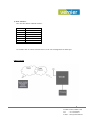
1
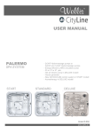
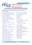
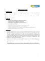
USER MANUAL for VE 100
INTRODUCTION
VE 100 is used for remote monitoring of field equipment via GPRS network. It can work on 2G networks and
provides reliable data connection between central monitoring software and remote field device. It is
designed to be used in industrial panels and operates on 9 ~ 36V DC power supply. It can also support
industry popular protocols such as MODBUS RTU for capturing data from field equipment and make it
available to SCADA systems.
FEATURES
•
•
•
•
•
•
•
•
•
Transparent data transmission over GPRS link to serial port.
Connects by itself to external server using static IP.
Self-embedded with integral PPP & TCP/IP protocol stack.
Local or Remote configuration
RTC support (battery backed)
Robust design with DIN rail mounting and wall mounting enclosure
Industrial Power Terminal block for 9V ~ 36V DC operation
1 console port (RS232) for local configuration, 1 RS232/ RS485 port for RTU interface.
Customized protocol support possible on request
OPERATION
VE 100 is configured as TCP Client. It connects automatically u si n g GPRS network to Internet.
Application software (such as SCADA) will be running on a server having static IP and access for clients
via internet. VE 100will establish connection with TCP socket of application software. Once
connected, transparent logical channel is created between serial port of VE 100and application
software. Thus application software can communicate with remote serial devices using this channel in any
required protocol. This feature allows remote connectivity of field devices on RS485/Rs232 using
GPRS router, without any extra other software.
If GPRS link is disconnected, V E 1 0 0 will attempt for connection after redial interval. If GPRS link is
disconnected d ue to poor network signal strength, VE 100will attempt for connection once network
signal strength restores.
Panel configuration can be done before putting it in the system through serial console interface.
Configuration parameters will be real time clock, GPRS dialing parameters, RTU serial port parameters etc.
1
LED INDICATIONS
Power ON LED: always ON.
Network status LEDs: Blinked twice at power ON.
After power on, these will be ON/OFF as per network signal strength. Excellent
(All 3 LEDs ON),
Good (2 LEDs ON), Poor
(1 LED ON),
No network available (All 3 LEDs OFF)
CONNECTION DETAILS
1) Configuration parameters settings:
a) Connect VE 1 0 0 to PC serial port using RS232 serial cable (Console port) for doing configuration
settings.
b) Run HyperTerminal on PC. Select com port. Make com port settings as baud rate
115200, 8 data bits, 1 stop bit, parity none and flow-control none.
c) Use one to one Serial cable. (9 pin D type)
Serial cable details: 9 pin male (GS100-Console port) to 9 pin female (PC com port side).
Sr. No.
1
2
3
9 pin male (GS100 side)
TXD (Pin no.2)
RXD (Pin no.3)
GND (Pin no.5)
9 pin female (PC com port side)
RXD (Pin no.2)
TXD (Pin no.3)
GND (Pin no.5)
d) Once connected on HyperTerminal, press ENTER key to go into router login. Here enter login
name admin, then press ENTER key. Then enter password as login password. Then
configuration can be done as per the requirement.
e) Once entered login name & password, Main menu will appear on screen. Main menu has 5
sub menus,
i) System menu
ii) RTU Serial port settings.
iii) Network connection menu.
iv) Service menu.
v) Status menu.
f) System menu has 3 sub menus
i) Location ID: - Sets Location ID (0001 – 9999) Enter 4 digits to set Location ID. ii) Set
Time: - Sets date & time
iii) Default settings: - Sets APN = internet (IDEA provider), redial interval = 9.
2
g) RTU serial port menu has following settings, i) Baud
rate (1200 to 115200)
ii) Data bits 8
iii) Parity (none)
iv) Stop bits (1)
h) Network connection menu has following settings, i) APN
name
ii) Access number (optional)
iii) User name (optional) iv)
Password (optional) v) Redial
Interval
i)
Service menu has following settings,
i) Connection Mode (Client-0, Server-1)
ii) Destination IP (Enter IP e.g. 192.168.002.001)
iii) Destination Port (Enter Port number in 5 digits e.g.01005)
j)
Status menu shows systems current status e.g. as per following
******************************************
SYSTEM STATUS
******************************************
Product description
: VE 100
Serial number
: 3377
Location ID
: 1234
Firmware version
: 1.0.0.2
System Date
: 01/11/0011
System Time
: 30:56:43
GSM Network Signal Strength
: Good (16) Internet
Connection Status
: Connected Network
IP address
:110.225.167.208
Server/Client Status
: Disconnected
Destination IP
: 219.64.202.224
Destination Port
: 12287
Service Type
: Transparent
*******************************************
3
2) RTU interface:
RTU has either RS232 or RS485 interface.
PIN no.
1
2
3
4
5
6
7
PIN details
TX (RS232)
RX (RS232)
GND
D+ (RS485)
D- (RS485)
9 ~36 V DC in
GND
Use suitable cable to connect field RTU devices to the VE 100using RS232 or Rs485 port.
APPLICATION
4
P.O Box: 234911, Dubai, UAE
Tel
: +971-4-2955966
Fax
: +971-4-2955977
E-mail : [email protected]