1
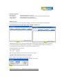
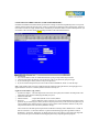
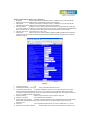
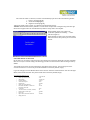
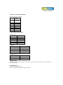
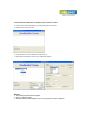
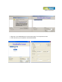
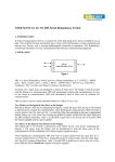
User Manual for VE10EK Serial to Ethernet Converter
Index
Technical Specifications …
Installation Procedure
…
LED Indications …
…
Configuration Procedure
Configuration through Utility
Configuration through HTTP
Factory Default setting
…
Communication Port Details
Cable Detail & Terminators
Power Supply
Virtual Com Port Utility
…
…
…
…
…
…
…
…
…
…
…
…
1
1
2
…
…
…
…
…
…
…
…
…
…
…
…
…
…
…
…
…
…
…
…
…
…
2
3
6
7
7
7
8
…
…
…
…
…
VE10EK is Serial to Ethernet Converter.
It is an Interface Converter between Ethernet and RS232 / RS485 / RS422 devices.
TECHNICAL SPECIFICATIONS
Communication Interfaces
Ethernet Interface
Serial Interface
Baud Rates
Network Protocols
Operation Mode
Configuration
Mechanical : Connectors
RS232
RS485/RS422
Ethernet
Dimensions
Power Supply
External Power Supply
Environmental
Operating Temperature
Relative Humidity
10 / 100 Base Mbps
Port RS232 / RS 485 / RS 422
300 bps to 115.2 Kbps
ARP, UDP, TCP, IP, ICMP, HTTP, DHCP
TCP Server/Client, UDP Client
Through a Utility on a PC and through HTTP
DB9 Male
4 Pin Howder
RJ45
89 * 69 * 27 mm ( W * D * H )
9 to 12V DC, 500mA
0°C to 55°C
10 to 90 % RH non-condensing
Table – 1
INSTALLATION PROCEDURE
⇒ Power ON the device.
⇒ The “SYS” LED (Red) will glow and flash.
⇒ Insert RJ45 jack into the RJ45 socket of the converter.
⇒ The “LAN” LED (green) will glow.
⇒ Connect the Serial Port Data LED (green) will blinking.
⇒ When you finish these procedures and LED displays are as shown, the hardware is properly installed and
On-line. You can use the Setup Tool VE 10EK Config.exe to setup the IP Address, Subnet Mask and
MAC Address. For the advance setup please use the IE or other Browsers. Refer to the section below for
details.
LED INDICATIONS
SYS “Red LED”
Data “Red LED”
LAN “Green LED”
P “Green LED”
: CPU health. Flashes once a second.
: While Transmiting & receiving any signal from network the LED will blink.
: When On-line the LED will remain on
: When the Power is on the LED will be ON.
RESET BUTTON
Press the Reset button. Turn ON the power and wait for 3 seconds. Converter will reset to factory default.
CONFIGURATION OF VE10EK USING TOOL VE10EK CONFIG.EXE
Figure 1
Figure 2
VE10EK Config Setup Tool is used to detect and setup the VE10EK on the Network. When you activate the tool
it will detect the installed VE10EK as shown in the Figure 1. The VE10EK CONFIG Setup Tool can setup only
one VE10EK at a time. Please shut down or off-line other VE10EK converters.
The Default IP address is 10.0.254.254
View -- Refresh (Figure 2).
View -- Exit
(Figure 2).
Note: Configuration happens only when the device password is empty.
VE10EK CONFIG.EXE SETUP TOOL FUNCTIONS
Figure 3 appears when you select Config option in fig 2.
IP Address setup , Subnet Mask setup : Key desired values as per network
Figure 3
Remark: Always run the View -- Refresh after any changes for confirmation
CONFIGURATION THROUGH HTTP (IE OR OTHER BROWSERS)
In addition of IP address and Subnet mask, specific device settings can be set through HTTP protocol. No special
software will be required. By pressing [Alt] + [Enter] or select [Device Settings] in the [Config] menu, will open a
new window in browser to login into the device. Alternatively, if IP address of the converter is already known, you
can connect to the converter directly by providing IP address in the URL field of browser.
Figure 5
¾
¾
¾
¾
¾
Activated IE
Key in the IP address of the VE 10EK hardware that is going to setup frame and press Enter.
The first Login frame will show up. You do not have to key in any Password, just press Login
If you cannot login, it means you have to key in the password.
If you do not know the password you can run the VE10EK CONFIG.exe “Reset” to reset the setup.
Note : If the domain of the converter is different from the computer running the browser, the login page won’t
appear unless the converter’s “Gateway Address” has been correctly set.
Login Screen Parameters ( fig 5 above )
√ System time elapsed : The time elapsed since start of this device [Day Hour: Minute: Second] format. This
information can be useful in identifying reliability of system.
√ Firmware release date.
√ Ethernet address
: Unique MAC (Media Access Control) address
√ Password
: Factory default is “empty”. However, it is not recommended to leave empty in field
operation. If you cannot login, it means you have to key the password. If you do not know the password you
can turn Off the power and then use any point tip to press “Reset” button and hold it and turn on the power.
The password will be reset to the factory default as “empty”.
The converter uses the same password protection mechanism commonly used in Windows NT or UNIX. If
there are more than “3 consecutive failures” in password check during login, the login function will be
disabled for “15 minutes”. During this 15 minutes period, even if you supply a correct password, login will
not proceed. This prevents intruder from finding the password by computer generated program.
Advance setup frame Parameters ( Fig 7 & 8 below )
1. IP address
: If DHCP client mode is enabled and there is a DHCP Server on the network, this
field will be assigned by DHCP server automatically otherwise enter manually.
2. Subnet mask
: If DHCP client mode is enabled and there is a DHCP Server on the network, this
field will be assigned by DHCP server automatically otherwise enter manually.
3. Gateway address
: Gateway is a device which connects local network to external network. Please type
it correctly. If there is no Gateway on the network, just leave as “0.0.0.0”. If DHCP client mode enabled and
there is a DHCP Server on the network, this field will be assigned by DHCP server automatically.
4. Network Link speed : Select between 10 / 100 / Auto
5. DHCP client
: DHCP client mode could be enabled / disabled. If DHCP enabled, there should be a
DHCP Server on the network. If DHCP disabled IP address, Subnet mask and Gateway address should be
manually assigned.
Figure 7
6.
7.
8.
9.
10.
11.
12.
13.
Socket port of HTTP
: 80
Destination IP Address / socket port
: Server’s IP address & Socket port no.
TCP socket inactive timeout : To identify whether the socket is active or dead. If there is no any data
transferred within the defined timeout period (1 to 99 minutes), then it probably a dead socket, and the
socket will be closed automatically. A new connection can be accepted again. The timeout period can be set
by users to fit different kinds of application.
Serial I/O settings
: Serial Com port Baud rate, Parity, Data bits, Stop bits
Interface of serial I/O
: Select RS232 or RS485/RS422
Packet mode of Serial input : Enabled / Disabled. If packet mode is enabled, the data from UART will be
deferred until the input buffer is full or the converter detects a 10-character packet gap and no more
characters arrive.
Device ID
: User assigned ID number for the converter. Available ID is “0 ~ 65535”.
Report device ID when connected
: Enable/disable. In TCP mode, if this parameter is enabled, every
time when the socket is connected, converter will immediately report device ID in the following formats:
i. Serial #1 nnnnnA[LF][CR]
ii. Serial #2nnnnnB[LF][CR]
iii. Digital I/O nnnnnC[LF][CR]
Total 8 bytes length, where “nnnnn” is 5-digit device ID assigned by the user.
Attention: If the VE10EK Gateway address is not same as the computer that is doing the setup, then the Login
frame will not appear unless the VE10EK Gateway address is setup same as the computer.
When finished, please press Update. The
“Controller updated now restarting ...” frame
will show (Figure 9).
When the frame is back to the Login frame which
means the advance setup it done, you can close the
browser.
FACTORY DEFAULT SETTING
By the chance, if you forget to setup password or have made incorrect settings, making the converter inoperable,
there are two ways to reset the setting. The following procedures can also be used to reset all settings to factory
default:
Turn Off the power of the converter and Press the reset button of the converter. Turn ON the power of the
converter and wait for 3 seconds. The password will RESET to the factory default. (empty).
Log in the web page. Press the RESET button of the converter. Select the UPDATE button. After Tx & Rx light
flashes, release the Reset button. The password will reset to the factory default (empty).
VE10 EK Default Parameters List
•
IP address
•
Socket port of serial I//O
•
Subnet mask
•
Gateway address
•
Network link speed
•
DHCP client
•
Socket port of HTTP setup
•
Destination IP address / socket Port
(TCP client and UDP)
•
Connection
•
TCP socket inactive timeout ( minutes)
•
Packet mode of serial input
•
Device ID
•
Report device ID when connected
•
Setup password
: 10.0.254.254
: 100
: 255.255.0.0
: 0.0.0.0
: Auto
: Disable
: 80
: 0.0.0.0
: Auto
: 10
: Disable
:1
: Disable
:
COMMUNICATION PORT DETAILS
RS232 Port Details of VE10EK
Pin No. SIGNAL of
VE10EK
9 Pin D
Male
2
RX
3
TX
5
GND
7
RTS
8
CTS
4
DTR
6
DSR
CABLE DETAILS OF VE10EK
For RS232 Side
VE10EK Side
TX
RX
RTS
CTS
DSR
DTR
COM Port Side
RX
TX
CTS
RTS
DTR
DSR
For RS422
SIGNAL of VE10EK
TX +
TX -RX +
RX --
Will Connect to
RX + of your device.
RX -- of your device.
TX + of your device.
TX – of your device.
For RS485, 2 wire
SIGNAL of VE10EK
Will Connect to
D+
D --
TX + of your device.
TX -- of your device.
TERMINATOR
VE10EK has Terminal resistors built in. If the switch 1 & 2 are set in “ON” position, 120 Ω are connected
between the signals.
POWER SUPPLY
230V AC External Adapter OR
24V DC Powered through 2 Pin screw type connector
CONFIGURATION FOR VIRTUAL SERIAL PORT CONSOLE :VER 2.7
¾ Unzip from VE10EKConfig\Virtual Com\Vserport.zip in the enclosed CD.
¾ Double click on required exe File .
¾ Follow the below screens to install the Virtual Com Port.
¾ Right Click inside the above screen to get “Add the Port Option “
Add Port
¾ The following screens below will appear.
¾ Select “ Continue Anyway”.
¾ Selected COM Port will be Added. Port no’s 8 in the picture is only for reference.
¾ Right Click on the added COM port & choose Add Net option. The snap shots are below
¾ In the next screen you are required to insert Network details
Following screens are the confirmation of the IP selected & communication established
Congratulations!!! The Virtual Com Port is installed
P.O Box: 234911, Dubai, UAE
Tel
: +971-4-2955966
Fax
: +971-4-2955977
E-mail : [email protected]