1
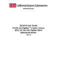
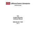
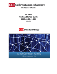
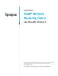
ZIC2410 Series CEL Profile-Builder Software Manual 0005-05-08-16-001 (Rev C) CEL Profile-Builder Software Manual Table of Contents 1 INTRODUCTION ................................................................................3 1.1 REFERENCED DOCUMENTS........................................................................ 3 2 INSTALLATION ..................................................................................3 2.1 INSTALLING THE PROFILE-BUILDER PROGRAM .................................... 3 3 STARTING PROFILE-BUILDER .......................................................6 3.1 STEP 1: GENERATING A CLUSTER FROM THE CLUSTER LIBRARY... 8 3.1.1 Generating a Cluster ..................................................................................................... 8 3.1.2 Generating an Attribute ................................................................................................ 9 3.2 STEP 2: GENERATING A ZIGBEE PROFILE AND LOGICAL DEVICE .. 10 3.2.1 Generating a Profile .................................................................................................... 11 3.2.2 Creating a Logical Devices......................................................................................... 12 3.3 STEP 3: GENERATING A ZIGBEE PHYSICAL NODE ............................. 14 3.3.1 Initializing a ZigBee Node ........................................................................................... 15 3.3.2 Generating End-points ............................................................................................... 16 3.4 STEP 4: BUILDING A SOURCE FILE ........................................................ 18 3.5 STEP 5: ADDING A FILE TO KEIL PROJECT .......................................... 18 4 REVISION HISTORY .......................................................................18 A WINDOWS VISTA OPERATING SYSTEM ....................................19 Rev C Document No. 0005-05-08-16-001 Page 2 of 19 CEL Profile-Builder Software Manual 1 INTRODUCTION This is the user manual for the CEL Profile-Builder program. Profile-Builder assists users in easily creating ZigBee™ profiles. In conjunction with a ‘C’ compiler, the user can create custom application capable of being programmed into the internal Flash memory of the ZIC2410. Profile-Builder is used by inputting the application requirements into the ZigBee profile format, which then modify a set of ‘C’ source files that become customized with the necessary functionality. The source files will contain both the ZigBee Device Object (ZDO) and ZigBee Device Profile (ZDP) descriptors, which define a ZigBee node and its functionality. The generated files can be integrated with the supplied CEL ZigBee Stack in order to create a user’s unique application. 1.1 REFERENCED DOCUMENTS Category Application Profile Stack API References filename (.pdf) 053520r25 zic04_zcl_api zic06_zdo_api Document Name ZigBee Home Automation Public Application Profile (from the ZigBee Alliance) ZIC2410 User Guide Profile and ZigBee Cluster Library (ZCL) ZIC2410 User Guide ZigBee Device Object (ZDO) 2 INSTALLATION The CEL Profile-Builder application has been tested under the Windows XP Professional operating environment. Support for Windows Vista is untested and cannot be guaranteed, but successful operation has been reported once Windows XP Compatibility has been enabled. For details on enabling Windows XP compatibility in the Windows Vista operating system see Appendix A of this document. 2.1 INSTALLING THE PROFILE-BUILDER PROGRAM The installation program for the CEL Profile-Builder application can be found on the CD in the \ZIC2410\Tools\CEL ZigBee Profile-Builder directory. The following is the detailed installation procedure. 1) Double click ‘Setup.exe’. The screen in Figure 1 will be displayed. Click ‘Next’. Figure 1 – Profile-Builder, Welcome Rev C Document No. 0005-05-08-16-001 Page 3 of 19 CEL Profile-Builder Software Manual 2) Read the License Agreement, select ‘I accept the items of the license agreement’ and click ‘Next’. Figure 2 – Profile-Builder, License Agreement 3) Type in a user name and company name and click ‘Next’. Figure 3 – Profile-Builder, Customer Information 4) Select the installation path and click ‘Next’. (By default, the installation path is set to C:\Program Files\CEL\CEL ZigBee Profile-Builder 3.00) Figure 4 –Profile-Builder, Installation Location Rev C Document No. 0005-05-08-16-001 Page 4 of 19 CEL Profile-Builder Software Manual 5) Click ‘Install’ to begin the installation. Figure 5 – Profile-Builder, Ready to Install 6) During installation the screen in Figure 6 will be displayed. Figure 6 – Profile-Builder, Setup Status 7) When the installation is complete the message below will display. Click ‘Finish’ to exit the installation process. Figure 7 – Profile-Builder, Installation Complete The CEL Profile-Builder application has been successfully installed. should now be displayed on your desktop. Rev C Document No. 0005-05-08-16-001 The icon Page 5 of 19 CEL Profile-Builder Software Manual 3 STARTING PROFILE-BUILDER Click on the Program-Builder icon on the user’s desktop; Figure 8 showing the opening window of the program should appear. Figure 8 – Screen, Profile-Builder (Opening) Profile-Builder includes the ZigBee 2006 standard cluster of the ZigBee Cluster Library and the complete device list defined in the Home Automation Profile. These files cannot be deleted or manually edited. For more detailed information, please refer to the “ZIC2410 User Guide Profile and ZigBee Cluster Library (ZCL)” supplied by CEL and the “ZigBee Home Automation Public Application Profile” document supplied by the ZigBee Alliance. Rev C Document No. 0005-05-08-16-001 Page 6 of 19 CEL Profile-Builder Software Manual The Profile-Builder screen consists of three main sections: a Cluster-Configurator, a Device-Configurator and an Application WorkSpace with the following functions: Cluster-Configurator: Defines the cluster from the ZigBee Cluster Library Device-Configurator: Defines an application profile and logical device. Application WorkSpace: Defines the physical ZigBee device. Using the ‘Build’ function, a user can define the functions of a ZigBee node in the three areas above and generate the ‘C’ source files and header files in the format required by the CEL ZigBee Stack. Figure 9 – Profile-Builder, Opening with explanations Caution: Profile-Builder can define profiles for both ZigBee 2004 and ZigBee 2006 versions. However, the ZIC2410 ONLY supports ZigBee 2006. Therefore, this document only explains how to define the ZigBee Cluster Library Profile for the ZigBee 2006 version. Table 1 describes the Toolbar of the Profile-Builder. Toolbar Table 1 – Profile-Builder Toolbar Items Keystroke Description Creates and initializes a .zprj file for a new File-New… Ctrl+N profile project. Menu File-Open Ctrl+O Loads a previously saved profile. File-Save Ctrl+S Stores the generated profile as a file. ZigBee Protocol Version Rev C Selects the targeted ZigBee version Document No. 0005-05-08-16-001 Page 7 of 19 CEL Profile-Builder Software Manual 3.1 STEP 1: GENERATING A CLUSTER FROM THE CLUSTER LIBRARY In the Cluster Configurator, a user can define a new cluster which is not already defined in the ZigBee 2006 Cluster Library. 3.1.1 Generating a Cluster Double-click one of functional domains (General, Closures, HVAC, Lighting, Measurement and Sensing, Security and Safety or Protocol Interface) in the Cluster Configurator Section. Right-click the mouse on the ‘Cluster List’ located below the cluster type. The pop-up menu of cluster operations as shown in Figure 10 will appear with the following choices: Insert User Cluster: Add new cluster. Remove All Clusters: Delete all clusters in the selected type. Remove Cluster: Delete selected cluster. Properties: Check and modify the setting value of cluster. Figure 10 – Profile-Builder, Cluster Operations Pop-up Rev C Document No. 0005-05-08-16-001 Page 8 of 19 CEL Profile-Builder Software Manual Select ‘Insert User Cluster’ to display the window in Figure 11. To define a new cluster, fill in the three fields and click ‘OK’: Functional Domain: The cluster type of ZigBee Cluster Library. Cluster Name: A unique cluster name in the ZigBee Cluster Library. Cluster ID: A unique cluster ID in the ZigBee Cluster Library. Figure 11 – Profile-Builder, Defining a New Cluster If either the Cluster Name or the Cluster ID is not unique, the “This cluster name (ID) already exists” message is displayed. If successful, a new cluster will be displayed in the Configurator Window as shown in Figure 12. Once the Cluster exists, attributes can be generated. Figure 12 – Profile-Builder, Cluster Generated 3.1.2 Generating an Attribute In the Cluster Configurator, double click on the cluster in which to add the attribute. Figure 12 will be displayed. Right-clicking the ‘Attribute List’ will bring up the pop-up menu in Figure 13. Add, delete or edit an attribute by selecting the corresponding item. Insert User Attribute: Add new attribute. Remove All Attribute: Delete all attributes in cluster. Remove Attribute: Delete selected attribute. Properties: Check and modify the selected attribute. Figure 13 – Profile-Builder, Attribute Pop-up Rev C Document No. 0005-05-08-16-001 Page 9 of 19 CEL Profile-Builder Software Manual Click ‘Insert User Attribute’, and the window in Figure 14 is displayed. To define a new attribute, fill in the five fields and click ‘OK’: Functional Domain: The cluster type of ZigBee Cluster Library. Cluster Name: Cluster name to which this attribute is included. Attribute Name: Unique name within the cluster for the attribute. Attribute ID: The ID within the cluster for the attribute (Acceptable values: 0x00000xFFFF). Data Type: Data type (size) of the attribute. Figure 14 – Profile-Builder, Insert New Attribute As shown in Figure 15, a new attribute is generated after setting the attribute values. The user can add other attributes as shown above. Figure 15 – Profile-Builder, Generate New Attribute 3.2 STEP 2: GENERATING A ZIGBEE PROFILE AND LOGICAL DEVICE In the Cluster Configurator a specific application profile can be defined, such as a Remote Monitoring or Sensor Network. In addition, the logical device can be generated which defines the specific application such as Light On/Off, Switch On/Off, etc. through operations on the profile. A logical device is a functional unit, which defines the operation of a specific application. One logical device exists for every one End-point application in a physical ZigBee node. For example, if the End-point in operation is a 3-in-1 physical ZigBee node, it means that there are three logical devices (two lights and one switch). Rev C Document No. 0005-05-08-16-001 Page 10 of 19 CEL Profile-Builder Software Manual 3.2.1 Generating a Profile As shown in Figure 16, a pop-up menu for a profile can be generated by right-clicking the mouse on the profile name to add, modify or delete a profile. Insert User Profile: Add new user profile. Remove All Profiles: Delete all profiles. Remove Profile: Delete selected profile. Properties: Check and modify the selected profile. Figure 16 – Profile-Builder, Generating a Profile To define a new profile, select ‘Insert User Profile’ and fill in the two fields and click ‘OK’: Profile Name: Unique profile name (Spaces or special characters are not allowed.) Profile ID: Unique profile identification (Acceptable values: 0x0001-0xFFFF). Figure 17 – Profile-Builder, Inserting a New Profile Rev C Document No. 0005-05-08-16-001 Page 11 of 19 CEL Profile-Builder Software Manual As shown in Figure 18, a new profile is generated after adding the user-defined profile. Once a new Profile has been created, a logical device can be generated. Figure 18 – Profile-Builder, Creating a Profile 3.2.2 Creating a Logical Devices In the Device Configurator, double-click the profile to which the logical device is to be added. As shown in Figure 19, a menu for that device can be brought up by right-clicking the mouse on the ‘Device List’. Add or delete a device by selecting from the pop-up menu. Insert User Device: Add the user device to the selected profile. Remove All Devices: Delete all devices of the selected profile. Remove Device: Delete the specific device of the selected profile. Properties: Check and modify the specific device. Figure 19 – Profile-Builder, Generating a Logical Device Rev C Document No. 0005-05-08-16-001 Page 12 of 19 CEL Profile-Builder Software Manual By selecting ‘Insert User Device’, a new logical device can be defined. The screen in Figure 20 shows the fields needed to create the new device. In the logical device definition, the terms, ‘In’ and ‘Out’, mean that the node can receive or transmit within the selected cluster. To define a new logical device, fill in the three fields and choose from the cluster list while also checking ‘In’ and/or ‘Out’ as appropriate, and click ‘OK’. Profile Type: The list of profiles currently available to Profile-Builder. Device Name: A unique device name operating in the selected profile. Device ID: A unique ID for the device operating in the selected profile. (Acceptable values: 0x0001-0xFFFF.) Cluster List: The clusters for input and output in this device. Up to 8 input and output clusters may be specified. Figure 20 – Profile-Builder, Inserting a New Device When the logical device has been generated, a new logical device will be shown as in Figure 21. Figure 21 – Profile-Builder, Device List Outline Rev C Document No. 0005-05-08-16-001 Page 13 of 19 CEL Profile-Builder Software Manual 3.3 STEP 3: GENERATING A ZIGBEE PHYSICAL NODE In the Application Workspace, one physical ZigBee node can be defined using the following information. Application system information Network information Power and current dispersion information Logical function unit (End-point) information The information above is converted to the defined ZigBee Descriptor source code and stored in a file, named profile.h, to interface with the CEL ZigBee Stack. The detailed instructions within profile.h are shown as an example in Figure 22. Figure 22 – User Profile and Device List as defined in profile.h Rev C Document No. 0005-05-08-16-001 Page 14 of 19 CEL Profile-Builder Software Manual 3.3.1 Initializing a ZigBee Node A ZigBee node is initialized with the basic node information by right-clicking the mouse on ‘UnKnownNode’ in the Application Workspace and selecting ‘Initialize’. Figure 23 – Profile-Builder Pop-up, Initializing a Node As shown in Figure 23, the following choices are available through this pop-up menu: Initialize: Initializes the Application WorkSpace (initializes the Configuration and deletes the Endpoint List ). Configuration: Reviews or edits the currently stored ZigBee device information (the values of the node name and the settings of the entire descriptor). Insert EndPoint: Creates an End-point (Simple Descriptor) which includes Profile ID, Device ID and EndPoint ID. Remove All EndPoints: Initializes a Simple Descriptor by deleting all End-points. Remove EndPoint: Deletes selected End-point. Properties: Review or edit the setting values of a selected End-point. Rev C Document No. 0005-05-08-16-001 Page 15 of 19 CEL Profile-Builder Software Manual By selecting ‘Initialize’, the window in Figure 24 is displayed to define the node’s configuration. Input the ‘Node Name’ in the appropriate space and click ‘OK’. Node Name: Any name assigned to the ZigBee node. Figure 24 – Profile-Builder, Node Configuration For more detailed node setting information, please refer to the “ZIC2410 User Guide ZigBee Device Object” document. Once the new node is set, it will be displayed as shown in Figure 25. Once a new node has been created, an End-point can be generated. Figure 25 – Profile-Builder, Confirming Node Generation 3.3.2 Generating End-points An End-point is a single logical function required by the physical device to either receive a response from another device or to control another device. For example, if one ZigBee Node is a light switch that has four physical light switches, then four End-points are needed. Or, if a sensor in one ZigBee Node has two sensor inputs, two End-points are needed. Rev C Document No. 0005-05-08-16-001 Page 16 of 19 CEL Profile-Builder Software Manual To create a new End-point, right-click on ‘UnKnownNode’ in the Application Workspace and select ‘InsertEndPoint’ as shown in Figure 23 above. The Device List window in Figure 26 will be displayed. An End-point can be generated by inputting the desired values into the three fields and clicking ‘OK’. Profile Type: The name of profile which the End-point supports. Device Type: The type of the logical device of the End-point. EndPoint: A unique number assigned to each End-point (Acceptable values: 1240). Figure 26 – Profile-Builder, New EndPoint Note: It is recommended to assign the numbers of the End-points in order starting from 1. After generating an End-point, the results will be as shown in Figure 27. To generate an additional End-point, simply repeat the procedure above. Figure 27 – Profile-Builder, End-point Results Rev C Document No. 0005-05-08-16-001 Page 17 of 19 CEL Profile-Builder Software Manual 3.4 STEP 4: BUILDING A SOURCE FILE Once the profile and logical device including any End-points and Nodes have been created, use the ‘Build’ button to create the five ‘C’ header source files: ‘Profile.h’, ZZDO.h’, ‘ZZDO.c’, ‘ZZDO_CONF.h’ and ‘ZZDO_TYPE.h’. As shown in Figure 28 at the top of the Application Workspace, the directory into which these files are generated can be specified (The default directory is the ‘My Documents’ folder). Figure 28 – Profile-Builder, Building Source Files By clicking the ‘Build’ button Profile-Builder creates the ‘\C_Builder\’ directory in the defined path and generates the five files in that directory as shown in Figure 29. Figure 29 – Windows Explorer, Build Results 3.5 STEP 5: ADDING A FILE TO KEIL PROJECT The source files generated by Profile-Builder should be integrated into a working project. 4 REVISION HISTORY Revision A Date 3Sep08 B 13Jan09 C 11Jun09 Rev C Description Released Revised Table in Section 1.1; updated Hardware list in Section Error! Reference source not found. General Cleanup. Removed Hardware References. Added detailed installation instructions and Vista compatibility. Document No. 0005-05-08-16-001 Page 18 of 19 CEL Profile-Builder Software Manual A WINDOWS VISTA OPERATING SYSTEM CAUTION: When the Operating System is Windows Vista (instead of Windows XP), the user must set the compatibility mode of the software tool. 1) After installing CEL Profile-Builder right-click the desktop icon and click on ‘Properties’ in the pop-up menu. 2) Click on the ‘Compatibility’ tab. (It may be necessary to delete what is written in the ‘Start in’ field to access the ‘Compatibility’ tab) 3) As shown below, check the box for ‘Compatibility mode’ and select ‘Windows XP’. 4) Click ‘OK’. Figure 30 – Profile-Builder, Compatibility