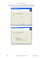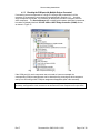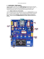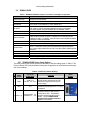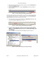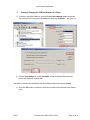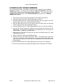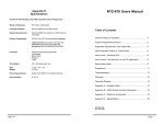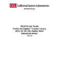
1
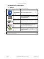
MeshConnect Family ZIC2410 Getting Started Guide 0005-05-08-11-001 (Rev E) ZIC2410 Getting Started Guide Table of Contents 1 INTRODUCTION .............................................................................. 3 1.1 1.2 1.3 DEFINITIONS ................................................................................................3 REFERENCED DOCUMENTS ......................................................................3 CEL ZIC2410 SYSTEM DESCRIPTION ........................................................3 2 ZICM2410P0-KIT2 COMPONENTS ................................................. 5 2.1 2.2 2.3 HARDWARE ..................................................................................................5 SOFTWARE...................................................................................................6 AVAILABLE DOCUMENTATION ..................................................................6 3 INSTALLING THE USB TO COM PORT DRIVER ........................... 7 3.1 INSTALLING THE DRIVERS .................................................................................7 4 EVALUATION BOARD USB INTERFACE ....................................... 8 4.1 CONNECTING TO UART1 THROUGH USB ................................................8 4.1.1 Enumerating the USB Drivers .......................................................................... 8 4.1.2 Identifying the COM Port for a Component .................................................. 11 4.1.3 Checking the COM port with Multiple Devices Connected.......................... 13 5 HARDWARE COMPONENTS ........................................................ 14 5.1 5.2 ZICM2410-EVB3 EVALUATION BOARD ...................................................14 ZICM2410-EVB3 .........................................................................................15 5.2.1 ZICM2410-EVB3 Power Supply Options ........................................................ 15 5.2.2 ZICM2410-EVB3 Default Settings ................................................................... 16 5.3 ZIC2410USB-WNA WIRELESS NETWORK ANALYZER ..........................16 5.3.1 THE ZIC2410USB-WNA FIRMWARE............................................................... 17 6 REVISION HISTORY ...................................................................... 18 A DEALING WITH COM PORT CONFLICTS .................................... 19 I. II. CHANGING THE DEVICE ID NUMBER ................................................................19 CHOOSING / CHANGING THE COM PORT NUMBER FOR A DEVICE .....................21 B REINSTALLING THE WNA FIRMWARE ....................................... 22 Rev E Document No. 0005-05-08-11-001 Page 2 of 22 ZIC2410 Getting Started Guide 1 INTRODUCTION This document provides a brief introduction on how to setup and configure the drivers required for interfacing the ZICM2410P0-KIT2 components and various software tools. Further, a brief overview of the evaluation boards supplied with the ZICM2410P0-KIT2 is also provided. 1.1 DEFINITIONS ZIC2410QN48: CEL’s single-chip IEEE 802.15.4 transceiver. ZICM2410P0-1: CEL’s IEEE 802.15.4 transceiver module. ZICM2410-EVB3: An evaluation board containing a ZICM2410P0 for development and evaluation purposes. Using the CEL supplied software tools makes it possible to download user-created programs to the ZIC2410. ZICM2410P0-KIT2: CEL’s IEEE 802.15.4 evaluation kit. ZIC2410USB-WNA: A Wireless Network Analyzer (WNA) used to monitor detailed information on each layer from the MAC to the Application layer by capturing RF packet data in real time. 1.2 REFERENCED DOCUMENTS Category Hardware Reference 1.3 filename [.pdf] Document Name ZICM2410-EVB3 Evaluation Board Hardware Reference zicm03_evb3_hwref Guide zic20_usbwna_ug ZIC2410WNA-USB User Guide CEL ZIC2410 SYSTEM DESCRIPTION The CEL ZIC2410 system of hardware components and software tools allows users, on their PCs, to easily and efficiently design and implement prototype wireless applications such as Security or Remote Sensing Networks. The process starts by creating custom applications. Existing application examples can be modified to suit the user’s needs or unique applications can be created using the supplied libraries and the tools of this easy-to-use program. Once the firmware has been created, it is compiled by Keil 8051 compiler and converted to programming files for each of the nodes. A CEL software program, known as the Device-Programmer, then allows the user to program the firmware to the memory space of the ZIC2410 either through a direct download or Over-The-Air (OTA). At the heart of system is the evaluation board, the ZICM2410P0-EVB3s, which houses the ZICM2410P0 IEEE 802.15.4 module. In addition, the evaluation board contains all the necessary peripherals to interface with the chip in order to implement a variety of applications and test scenarios. In order to monitor the newly created prototype network, CEL provides the Packet-Analyzer program and the ZIC2410USB-WNA Wireless Network Analyzer. The network traffic can be captured wirelessly for the purpose of testing or troubleshooting. The program’s multiple tools and views allow the user to display the information being sent in ways as complex as the frame details at each layer for an individual packet. Rev E Document No. 0005-05-08-11-001 Page 3 of 22 ZIC2410 Getting Started Guide Together, all of these individual items, which comprise the ZICM2410P0-KIT2 evaluation kit, combine to offer a powerful yet easily implemented solution. Rev E Document No. 0005-05-08-11-001 Page 4 of 22 ZIC2410 Getting Started Guide 2 ZICM2410P0-KIT2 COMPONENTS 2.1 HARDWARE Table 1 – Major Hardware Components Hardware Component Remarks ZICM2410-EVB3 CEL’s Evaluation Board for interfacing to a PC. Each board contains a ZICM2410 module. ZICM2410Px-1 CEL ZIC2410 Module Solution, each module contains a ZIC2410QN48 device. ZIC2410QN48 CEL Single Chip Solution contains a single-cycle 8051 microcontroller alongside an IEEE 802.15.4 compliant radio. ZIC2410USB-WNA The Wireless Network Analyzer is used in conjunction with the Packet-Analyzer program to wirelessly monitor packet traffic communications CEL Software CD Contains the necessary files to download all of the CEL Software components (programs and drivers), the Application Source files for example applications, and the CEL documentation. CAUTION: Components contain parts and assemblies susceptible to damage by Electrostatic Discharge (ESD). Rev E Document No. 0005-05-08-11-001 Page 5 of 22 ZIC2410 Getting Started Guide 2.2 SOFTWARE Table 2 – Software Components Software Component CEL Device-Programmer CEL Packet-Analyzer CP2101 Driver CP2101 USB ID SET Optional Software C Compiler 2.3 Software Manuals Stack API References Hardware References Datasheet Rev E Program to compile the device firmware files AVAILABLE DOCUMENTATION Category Kit User Guides Description Software for downloading device firmware onto the devices through the evaluation board Software used in conjunction with the ZIC2410-USBWNA to wirelessly monitor the traffic of packet data communicated within a network The software drivers necessary to connect any of the ZIC2410 components to the PC through a USB cable Software tool used to change the CP210x device ID when using multiple USB interfaces to the same PC. Table 3 – CEL ZIC2410 Series Documentation Document Name filename [.pdf] CEL Device-Programmer Software Manual zic00_devpro ZIC2410 User Guide Code Banking with Keil µVision zic05_codebank_ug CEL Packet-Analyzer Software Manual zic13_pktanlz_sm zic19_hal_api ZIC2410 User Guide Hardware Abstraction Layer API Reference zicm03_evb3_hwref zic14_pcbimp_ug zic20_usbwna_ug zic11_getstrt_sm zicm02_kit2_p2pdemo zic2410 MeshConnect_DS ZICM2410-EVB3 Evaluation Board Hardware Reference Guide ZIC2410 User Guide PCB Implementation Guide ZIC2410USB-WNA User Guide ZIC2410 Getting Started Guide ZICM2410P0-KIT2 User Guide, Point-to-Point Demonstration ZIC2410 Datasheet ZICM2410Px MeshConnect Series Datasheet Document No. 0005-05-08-11-001 Page 6 of 22 ZIC2410 Getting Started Guide 3 INSTALLING THE USB TO COM PORT DRIVER In order to interface a PC to the evaluation boards or the ZIC2410USB-WNA, a driver file must be installed onto the PC, allowing it to utilize the USB port. The USB to RS-232 driver installation file can be found on the CD in the \ZIC2410\Tools\Others\CP210X_DRIVER\ directory. 3.1 Installing the Drivers The following is the procedure to decompress the drivers: 1. Double-click on the “CP210x_VCPInstaller.exe” executable, if prompted by an Open File – Security Warning dialog box, click the Run button. 2. When the Silicon Laboratories CP210x USB to UART Bridge Driver Installer dialog is displayed, accept the default installation location and click the Install button. Figure 1 – Silicon Labs CP210X Driver Installation 3. Once the installation has completed successfully, click the OK button. Figure 2 - Silicon Labs CP210X Driver Installation Successful The CP210x Driver installation is now complete. Rev E Document No. 0005-05-08-11-001 Page 7 of 22 ZIC2410 Getting Started Guide 4 EVALUATION BOARD USB INTERFACE The ZIC2410 has two UART interfaces, UART0 and UART1. UART0 is typically used for general communication purposes, while UART1 is used to interface to the various software tools (i.e. Device Programmer, etc.). UART1 can also be used for general communication when not interface to the various software tools. On the evaluation boards either one or both UARTs are present, when only one UART interface is present it will always be UART1. The evaluation boards utilize a Serial-to-USB interface chip; as such the UARTs have USB interfaces. The balance of this document will assume a UART1 connection; however the procedures for installing drivers, etc. are the same for UART0 when present. 4.1 CONNECTING TO UART1 THROUGH USB NOTE: Before connecting an evaluation board to a PC via USB, install the CP210x USB Driver. For installation information refer to Section 3 of this document. This procedure is written for an evaluation board however it applies to the ZIC2410USBWNA, as well. This procedure must be run for each component as it is connected to the PC and powered on. 4.1.1 Enumerating the USB Drivers When an evaluation board or other USB component is connected to the PC for the first time and powered on, the PC will respond that it has detected new hardware. The following is the procedure for enumerating the new hardware on the PC using the ‘Found New Hardware Wizard’. 1) First, connect an evaluation board to the PC using a USB cable. Power the evaluation board by placing the ‘POWER SWITCH’ in the ‘VREG’ or ‘USB’ position. A LED should illuminate indicating that power has been applied to the evaluation board. After a few seconds, the screen in Figure 3 should appear. Figure 3 - Screen, New Hardware Wizard (Installation Method) 2) Either of the two choices given in Figure 4 will correctly install the new hardware onto the PC, but the automatic installation will take more time because it must search for Rev E Document No. 0005-05-08-11-001 Page 8 of 22 ZIC2410 Getting Started Guide the driver software. If the CP210x drivers have been installed in the default destination directory, choose ‘Install from a list or specific location (Advanced)’ and click ‘Next’. 3) In the Please choose your search and installation options dialog, un-check the ‘Search removable media (floppy, CD-ROM…)’ and check the ‘Include this location in the search:’ check boxes, as shown in Figure 4. Figure 4 – Screen, New Hardware Wizard (Choosing to Search for Driver) 4) Click the ‘Browse’ button and navigate to the C:\SiLabs\MCU\CP210x\Windows_XP_S2K3_Vista_7 directory and click the ‘OK’ button. 5) Upon completing the search field, click the ‘Next’ button. Figure 5 – Screen, New Hardware Wizard (Driver Location) Rev E Document No. 0005-05-08-11-001 Page 9 of 22 ZIC2410 Getting Started Guide 6) The screens in Figure 6 and Figure 7 will appear while the driver file is being initialized. When that process is complete, Figure 8 will appear. Click ‘Finish’. Figure 6 - Screen, New Hardware Wizard (Setting a System Restore Point) Figure 7 - Screen, New Hardware Wizard (Installation Status) Rev E Document No. 0005-05-08-11-001 Page 10 of 22 ZIC2410 Getting Started Guide Figure 8 - Screen, New Hardware Wizard 7) If Windows prompts to reboot the system due to a system settings change, click ‘Yes’ to complete the installation. 8) The hardware drivers for the USB connected ZIC2410 device have now been successfully enumerated. 4.1.2 Identifying the COM Port for a Component When a new piece of hardware is connected to the PC via the USB port, the PC assigns that connection a COM port number. It is necessary to determine the COM port number on the PC, to which the component has been assigned. The Device Manager utility included with Windows can be used to do so, and to check that the hardware and associated drivers have been properly installed. To check which COM port the installed component is connected to, please follow the following steps. 1) Right-click the mouse on ‘My Computer’ menu. either on the desktop or in the ‘Start’ 2) Select ‘Properties’ and the ‘System Properties’ window in Figure 9 will be displayed. Figure 9 – Screen, Windows (System Properties) Rev E Document No. 0005-05-08-11-001 Page 11 of 22 ZIC2410 Getting Started Guide 3) In the ‘System Properties’ screen, under the ‘Hardware’ tab, click on ‘Device Manager’. Double-click on ‘Ports (COM & LPT)'. The screen in Figure 10 will be displayed Figure 10 – Screen, Device Manager (1 device connected) 4) On the list of Ports, one of them should read ‘Silicon Labs CP210x USB to UART Bridge (COM#)’. In the example in Figure 10 above, the component is connected to ‘COM5’. NOTE: It is important to take note here of the COM port that has been assigned to the component, as it will be needed later when establishing connections with the various software tools. ZIC2410 Getting Started Guide 4.1.3 Checking the COM port with Multiple Devices Connected If connecting several components to a single PC through USB connections it will be necessary to enumerate the new component as performed in Section 4.1.1. As with a single component connected, it is necessary to identify the individual COM ports used for each component. The Device Manager will not distinguish between individual components, but rather will display identical ‘CP210x USB to UART Bridge Controller (COM#)’ entries as shown in Figure 11. Figure 11 – Screen, Device Manager (2 devices connected) If the COM port # for each component was not noted as it was enumerated, the corresponding COM port assignments can be determined by powering off each component one-by-one and noting which COM port assignment disappears (after a few seconds). NOTE: If multiple components have the same COM port assignment (i.e. two components register as COM4), see Appendix A of this document to set the Device ID of the component to a unique value. Rev E Document No. 0005-05-08-11-001 Page 13 of 22 ZIC2410 Getting Started Guide 5 HARDWARE COMPONENTS The major hardware components of the ZICM2410P0-KIT2 Development Kit are the three ZICM2410-EVB3 evaluation boards and ZIC2410USB-WNA Wireless Network Analyzer. A brief description of the evaluation board and WNA follows, for further details on the evaluation board please refer to the evaluation board’s hardware reference guide. 5.1 ZICM2410-EVB3 EVALUATION BOARD This section briefly describes each component and function of a ZICM2410-EVB3 evaluation board. It is advised that one becomes familiar with the information contained in this section prior to using the evaluation hardware. For more detailed information on the evaluation board, please refer to the “ZICM2410-EVB3 Evaluation Board Hardware Reference Guide”. Figure 12 shows the ZICM2410-EVB3 with its major components and functions identified. Figure 12 - Photo, ZICM2410-EVB3 Evaluation Board ZIC2410 Getting Started Guide 5.2 ZICM2410-EVB3 Table 4 – ZICM2410-EVB3 Descriptions / Functions of the Major Components Components Description / Function Microphone input and Headphone output for connection when using the evaluation Audio / Voice Jacks board’s voice / audio features. ZICM2410 Module ZICM2410 module. The DUT of the evaluation board 3 ea 10-pin DIP Switches used for disconnecting the evaluation boards connections DIP Switches to the various on board features (i.e. LEDs, switches, etc.). ISP Mode Switch: 2-position slide switch to control ISP mode ISP Switch ‘ISP’ position is used for downloading application firmware to the ZICM2410. For normal operation, the switch should be set to the ‘NORMAL’ position. RESET Switch Button switch to reset the device MPU (Active Low) General Purpose LEDs Four Indicator LEDs for GPIO output tests Push Button Switches connected to General Purpose I/O (GPIO) Ports: When a button is pressed, the signal ‘0’ is applied to the corresponding port pin. Test Tact Switches Otherwise, a value of ‘1’ is applied. Switch #3 and #4 can be configured as external interrupts to the 8051 microcontroller. Battery Holders Holder for 2 ea. 1.5 Volt Type AA Batteries DC JACK Input for a 5.0 – 9.0 Volt DC Power Supply This three-position slide switch is used to select the power source for the evaluation board. In the position ‘VREG’, power is supplied either through the USB port or POWER Switch from a power supply inserted in the DC Jack. In the ‘VBAT’ position, batteries provide the power. Power Indicator LED LED indicates when DC power is turned on. USB Port Port to connect the evaluation board through a USB cable to a PC. Variable Resistors for testing ADC functions in the ZICM2410P0 module ADC Variable Resistors Current Monitor pins For measuring operating current of the module under various conditions 5.2.1 ZICM2410-EVB3 Power Supply Options The three position slide switch operates in accordance with the settings given in Table 5. The Power Indicator LED (red) illuminates when power is applied to the evaluation board through any of the methods. Table 5 – EVB3 Power Switch Settings Power Switch Position VCC Power Supply Value 1 VREG VUSB: 5.0 V DC Jack: 5.0 – 9.0 V 2 VBAT 3.0 V 3 VREG + J4 ZIC2410-EVB3: 5 V ZICM2410: 2.1 – 3.0V # Comments In this position the evaluation board and module are either powered from the USB interface or through the DC Jack from an external supply. In this position the evaluation board and module are powered from the two 1.5 V Type AA batteries. In this position the evaluation board is powered via either the USB interface or through the DC Jack. The ZICM2410 module is powered externally via the J4 header. See the “ZICM2410-EVB3 Evaluation Board Hardware Reference Guide” for further details. Switch Position ZIC2410 Getting Started Guide 5.2.2 ZICM2410-EVB3 Default Settings For normal operation of the evaluation board, the jumpers and DIP switches should be placed in the following locations: Connector J9 J200 U203 U204 U205 5.3 Settings 1-2 Open 1: ON, 2: ON, 3: ON, 4: ON, 5: ON, 6: ON, 7: ON, 8: ON, 9: ON, 10: ON 1: ON, 2: ON, 3: ON, 4: ON, 5: ON, 6: ON, 7: ON, 8: ON, 9: ON, 10: ON 1: ON, 2: ON, 3: ON, 4: ON, 5: ON, 6: ON, 7: ON, 8: ON, 9: ON, 10: ON ZIC2410USB-WNA WIRELESS NETWORK ANALYZER The MeshConnect ISP / WNA USB dongle contains 3 status LEDs (Amber, Red and White) and three user-accessible switches (two push-button and one slider). Table 6 and Table 7 detail the various statuses indicated by the LEDs and the functions of the various switches. Figure 13 details the locations of the various switches and LEDs of the MeshConnect ISP / WNA. LABEL COLOR Active Amber Power Red ISP White DESCRIPTION Indicates whether the MeshConnect ISP / WNA received a valid packet (SMAC or MAC) when operating in WNAmode. Indicates whether the MeshConnect ISP / WNA is powered. When the RED LED is illuminated, sufficient power has been applied, when off the ISP / WNA is not powered. Indicates the MeshConnect ISP / WNA operating mode, when the WHITE LED is illuminated the ISP / WNA is in ISP-mode (the MS2 / ISP output of the dongle is ‘1’), when off the ISP / WNA is in WNA-mode (the MS2 / ISP output of the dongle is ‘0’). Table 6: Status LED Descriptions NAME / LABEL TYPE DESCRIPTION (Remote) Reset Push Button (Remote) ISP Push Button Toggles the MeshConnect ISP / WNA Remote RESET output when the MeshConnect ISP / WNA is in ISP-mode. When pressed, the target device is placed in RESET. Toggles the MeshConnect ISP / WNA operating mode, when the WHITE LED is illuminated the ISP / WNA is in ISP-mode, when off the ISP / WNA is in WNA-mode. WNA Reset SPST Slider Resets the MeshConnect ISP / WNA USB dongle. Table 7: Switch Descriptions Rev E Document No. 0005-05-08-11-001 Page 16 of 22 ZIC2410 Getting Started Guide NORMAL RESET WNA Reset Figure 13: CEL MeshConnect ISP / WNA USB Dongle 5.3.1 THE ZIC2410USB-WNA FIRMWARE The ZIC2410-USBWNA is shipped with its firmware preprogrammed. If the firmware is somehow erased or corrupted, it must be reloaded prior to running Packet-Analyzer. Please refer to Appendix B of this document for further instructions. ZIC2410 Getting Started Guide 6 REVISION HISTORY Revision A Date 3Sep08 B 13Jan09 C 11Jun09 D 18Jun10 E 24Sep10 Rev E Description Released Added ZICM2410-EVB2 evaluation board information; Corrected ZIC2410-EVB to -EVB1 throughout the document; Corrected Table in Section 1.2; added EVB2 and Px module to Table 1; Corrected HARDWARE descriptions in Section 1.1; Modified Section 1.3 for new EVB2; updated Table 3; added filenames to referenced documents throughout Remove CEL software application installation details and moved to respective software manuals. Removed Ethernet connection information (unsupported). Removed references to the EVB1 and EVB2 hardware and replaced with EVB3 throughout. Added WNA hardware details. Modified to incorporate the ZIC2410-USBWNA as the replacement of the ZIC2410-WNA. Corrected WNA Part Numbering. Removed references to ZigBee demonstrations and updated. Updated CP210x driver installation to Silicon Labs latest release. Document No. 0005-05-08-11-001 Page 18 of 22 ZIC2410 Getting Started Guide A DEALING WITH COM PORT CONFLICTS i. Changing the Device ID Number The ZIC2410 components which connect to a PC through a USB cable (i.e. evaluation boards) contain a Cygnal CP2101 Single Chip USB to UART Interface Bridge. All of the Cygnal devices are manufactured with the same serial number (0001). If you have purchased an evaluation kit, all components contained in the kit should have had their serial numbers changed to a unique value. In general, the evaluation boards in the kit have serial numbers of 0001, 0002, 0003, etc., and the ZIC2410USB-WNA will have a serial number of 0010. If the user is running multiple WNA’s from a single PC, or combining boards from multiple kits and connecting several of them through USB cables simultaneously to the same PC, one or more of the connected devices may have the same serial number. This may cause communication problems, if the PC is unable to distinguish them apart. To resolve any conflict, run the following procedure to discover and/or change the serial number of any of the ZIC2410 components. Figure 14 – Screen, Windows Explorer (Running CP210xSetIDs Program) 1) To change the serial number, connect only the device which is to be changed (e.g. an evaluation board) to the PC and double click CP210xSetIDs on the CP210xSetIDs executable in the directory \ZIC2410\Tools\Others\CP210X_USB_ID_SET\ found on the supplied CD. The window in Figure 14 will appear. 2) The serial number box at the top of the screen will have the complete Device ID number, in this example it is the ‘0001’ part of ‘00#0001_00#’ as shown in Figure 15. Figure 15 – Screen, CP210x Set IDs (Changing Device ID #’s) Rev E Document No. 0005-05-08-11-001 Page 19 of 22 ZIC2410 Getting Started Guide 3) While in this window, type the new serial number (e.g.0004), in the lower ‘Serial Number’ box and check the ‘radio box’ to its left. 4) Press the ‘Program Device’ button. The upper ‘Serial Number’ box will become blank as shown in Figure 16. Figure 16 – Screen, CP210x Set IDs (Executing ID # Change) If the serial number selected has not been used before on this PC, the user will be prompted that two new hardware devices have been found. Follow the procedure given in Section Error! Reference source not found. of this document to install the two new devices. 5) Once both hardware devices have been installed click on ‘Update Device List’ and the serial number will be changed to ‘0004’ as shown in Figure 17. Figure 17 – Screen, CP210x Set IDs (ID # Change Complete) 6) To ensure that the process has been completed successfully, the user can check in ‘Device Manager’. In ‘Ports (COM & LPT)’ double-click on the new ‘CP2101 USB to UART…’ port (Note that it has a new COM port number (See Section 4.1.2 for instructions on using Windows ‘Device Manager’). 7) Under the ‘Details’ Tab, the new ID number will be displayed as shown in Figure 18. Figure 18 – Screen, Device Manager (Checking ID # Change) Rev E Document No. 0005-05-08-11-001 Page 20 of 22 ZIC2410 Getting Started Guide ii. Choosing / Changing the COM Port Number for a Device 1) To choose or change the COM port, open the Windows Device Manager window and doubleclick on the device to be changed in the ‘Ports’ list to bring up its ‘Properties’. See Figure 19. Figure 19 – Screen, Device Manager (Changing Port Settings) 2) Under the ‘Port Settings’ tab, click on ‘Advanced’, choose the desired COM port number from the pull down menu, and click ‘OK’. Note that the pull down menu will show the user what COM port numbers are currently ‘(in use)’. 3) Once the ‘OK’ button is clicked, the COM port number will be changed to the chosen value Rev E Document No. 0005-05-08-11-001 Page 21 of 22 ZIC2410 Getting Started Guide B REINSTALLING THE WNA FIRMWARE In the event that the firmware in the WNA is damaged, it can be reinstalled using the DeviceProgrammer software. For details on the screens of the Device-Programmer, please refer to “ZIC2410 User Guide Device-Programmer Software Manual”. For more details on the mechanics and switch locations of the ZIC2410USB-WNA please refer to the “ZIC2410USBWNA User Guide”. 1. Disconnect (if connected) the target board from the dongle’s ISP interface. 2. Unplug the MeshConnect ISP / WNA USB dongle from the PC. 3. Open the MeshConnect ISP / WNA by gently prying the top of the plastic cover from the bottom (be careful not to lose the push-button inserts). 4. Slide the WNA ISP switch to the ISP position (See the Status LEDs and Switches section of this document for the switches location). 5. Insert the MeshConnect ISP / WNA USB dongle back into one of the PCs USB ports. 6. Use the CEL Device-Programmer software tool to program the firmware onto the USB dongle. The firmware is contained on the MeshConnect CD, the filename is MESHCONNECT_WNA_ISP_DONGLE.HEX. 7. When finished, close Device-Programmer and remove the MeshConnect ISP / WNA USB dongle from the PC. 8. Slide the WNA ISP switch to the NORMAL position. 9. Replace the cover to the MeshConnect ISP / WNA. The easiest way to replace the cover is to hold the top cover upside-down, re-insert the push-button inserts, then gently place the dongle body into the top cover aligning the pins and squeeze the two pieces together. 10. Insert the MeshConnect ISP / WNA USB dongle into one of the PCs USB ports. 11. Re-connect (if previously connected) the target board to the dongle’s ISP interface. Rev E Document No. 0005-05-08-11-001 Page 22 of 22