1
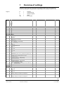
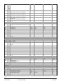
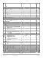
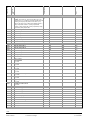
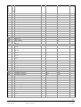
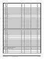
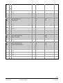
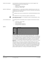
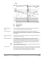
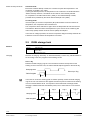
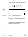
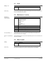
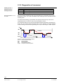
Albatros2
Heat Pump Controller
User Manual OEM
Edition 2.0
Controller series B
CE1U2355en_01a
14. June 2006
RVS51.843
AVS75..
AVS37..
QAA75..
QAA78..
QAA55..
Siemens Schweiz AG
HVAC Products
2/32
Siemens Schweiz AG
HVAC Products
User Manual OEM RVS51.843
CE1U2355en_01a
14. June 2006
Contents
1
Overview of settings ........................................................................................ 5
2
The settings in detail...................................................................................... 18
2.1
Operator section ............................................................................................ 18
2.2
Heating circuits / cooling circuit ..................................................................... 18
2.3
DHW .............................................................................................................. 19
2.4
Heat pump ..................................................................................................... 19
2.5
DHW storage tank ......................................................................................... 24
2.6
Configuration ................................................................................................. 26
2.7
Fault............................................................................................................... 27
2.8
Maintenance / service.................................................................................... 27
2.9
State of plant ................................................................................................. 27
2.10
Diagnostics of consumer ............................................................................... 28
3/32
Siemens Schweiz AG
HVAC Products
User Manual OEM RVS51.843
Contents
CE1U2355en_01a
14. June 2006
4/32
Siemens Schweiz AG
HVAC Products
Benutzerhandbuch RVS51.843
Contents
CE1U2355en_01a
14. June 2006
1
Overview of settings
The table on the following pages shows all available settings up to the OEM level.
Certain operating lines may get hidden, depending on the controller version in use.
E
I
F
O
ZN
Min
Max
Unit
enduser
commissioning
heating engineer
OEM
line number
Default value
=
=
=
=
=
25.03
25.10
00:00
01.01
2004
01.01
01.01
23:59
31.12
2099
31.12
31.12
hh:mm
dd.mm
yyyy
dd.mm
dd.mm
*
1
8
-
*
1
2
-
*
0
2
-
*
0
1
-
*
0
1
-
*
0
1
*
0
1
*
1
4
-
*
1
2
-
*
1
2
-
*
1
2
-
*
0
3
-
Readjustment room sensor
Software version
0.0
-
-3
0
3
99.9
°C
-
Binding
*
0
1
*
0
1
-
0
3
-
-
0
3
-
Operating
level
Function
Operating line
Legend
Time of day and date
1
2
3
5
6
E
E
E
F
F
Hours/minutes
Day/month
Year
Start of summertime
End of summertime
Operator section
20
E
Language
German* ¦ …
22
F
Info
Temporarily* ¦ Permanently
24
F
Lighting
Off ¦ Temporarily* ¦ Permanently
26
F
Operation lock
Off* ¦ On
27
F
Programming lock
Off* ¦ On
30
O
Read data
No* ¦ Yes
31
O
Write data
No* ¦ Yes
40
I
Used as
Room unit 1* ¦ Room unit 2 ¦ Operator unit ¦Service unit
42
I
Assignment room unit 1
Heating circuit 1* ¦ Heating circuits 1 and 2
44
I
Operation HC2
Commonly with HC1* ¦ Independently
46
I
Operation HCP
Commonly with HC1* ¦ Independently
48
I
Action occupancy button
None ¦ Heating circuit 1* ¦ Heating circuit 2 ¦ Commonly
54
70
F
F
Wireless
120
I
No* ¦ Yes
121
I
Test mode
Off* ¦ On
130
I
Room unit 1
Missing ¦ Ready ¦ No reception ¦ Change batt
131
I
Room unit 2
Missing ¦ Ready ¦ No reception ¦ Change batt
5/32
Siemens Schweiz AG
HVAC Products
User Manual OEM RVS51.843
1 Overview of settings
CE1U2355en_01a
14. June 2006
Operating line
Operating
level
Function
Default value
Min
Max
Unit
132
I
-
0
3
-
Outside sensor
Missing ¦ Ready ¦ No reception ¦ Change batt
133
I
Repeater
-
0
3
-
-
0
3
-
-
0
3
-
*
0
1
-
*
0
9
-
6:00
22:00
24:00
24:00
24:00
24:00
*
00:00
00:00
00:00
00:00
00:00
00:00
0
24:00
24:00
24:00
24:00
24:00
24:00
1
hh:mm
hh:mm
hh:mm
hh:mm
hh:mm
hh:mm
-
*
0
9
-
00:00
05:00
24:00
24:00
24:00
24:00
*
00:00
00:00
00:00
00:00
00:00
00:00
0
24:00
24:00
24:00
24:00
24:00
24:00
1
hh:mm
hh:mm
hh:mm
hh:mm
hh:mm
hh:mm
-
--.---.-*
01.01
01.01
0
31.12
31.12
1
dd.mm
dd.mm
-
20.0
19
10.0
35.0
0.8
0.0
ZN 712
ZN 714
4
ZN 710
0.10
-4.5
ZN 716
ZN 710
ZN 712
35
4.00
4.5
°C
°C
°C
°C
°C
Missing ¦ Ready ¦ No reception ¦ Change batt
134
I
Operator unit
Missing ¦ Ready ¦ No reception ¦ Change batt
135
I
Service unit
Missing ¦ Ready ¦ No reception ¦ Change batt
138
I
Delete all devices
No* ¦ Yes
Time prog heating circuit 1
500
E
Preselection
Mo – Su* ¦ Mo - Fr ¦ Sa - Su ¦ Mo ¦ Tu ¦ We ¦ Th ¦ Fr ¦ Sa
¦Su
501
502
503
504
505
506
516
E
E
E
E
E
E
E
1st phase on
1st phase off
2nd phase on
2nd phase off
3rd phase on
3rd phase off
Default values
No* ¦ Yes
Time prog heating circuit 2
520…536
Time program 3 / P
540…556
Time program 4 / DHW
560
E
Preselection
Mo – Su* ¦ Mo - Fr ¦ Sa - Su ¦ Mo ¦ Tu ¦ We ¦ Th ¦ Fr ¦ Sa
¦Su
561
562
563
564
565
566
576
E
E
E
E
E
E
E
1st phase on
1st phase off
2nd phase on
2nd phase off
3rd phase on
3rd phase off
Default values
No* ¦ Yes
Holidays heating circuit 1
642
643
648
E
E
E
Start
End
Operating level
Frost protection* ¦ Reduced
Holidays heating circuit 2
650…658
Holidays heating circuit P
660…668
Heating circuit 1
710
712
714
716
720
721
E
E
E
F
E
F
Comfort setpoint
Reduced setpoint
Frost protection setpoint
Comfort setpoint max
Heating curve slope
Heating curve displacement
6/32
Siemens Schweiz AG
HVAC Products
User Manual OEM RVS51.843
1 Overview of settings
CE1U2355en_01a
14. June 2006
Operating line
Operating
level
Function
Default value
Min
Max
Unit
726
F
*
0
1
-
Heating curve adaption
Off* ¦ On
730
732
740
741
750
760
770
780
E
F
I
I
F
F
F
F
Summer/winter heating limit
24-hour heating limit
Flow temp setpoint min
Flow temp setpoint max
Room influence
Room temp limitation
Boost heating
Quick setback
18
-3
8
50
20
1
−−−
*
−−−/8
− − − / -10
8
ZN 740
−−−/1
− − − / 0.5
−−−/0
0
30
10
ZN 741
95
100
4
20
2
°C
°C
°C
°C
%
°C
°C
-
0
0
−−−
-15
Off
0
0
− − − / -30
-30
0
360
360
10
ZN 800
1
min
min
°C
°C
-
0
*
0
0
50
1
°C
-
2
120
32
120
*
0
30
1
10
0
20
873
100
873
4
°C
s
°C
s
-
25
0
0
*
0
0
0
0
95
95
32
2
°C
°C
-
1
0
1
-
24
1
ZN710
1
35
4
°C
-
20
16
24
48
26
30
2
18
18
100
1
1
8
8
8
8
20
20
1
8
8
1
0.5
0
35
35
35
100
35
35
10
35
35
100
4
1
°C
°C
°C
h
°C
°C
°C
°C
°C
°C
°C
-
Off ¦ Down to reduced setpoint* ¦ Down to frost prot
setpoint
790
791
800
801
820
F
F
F
F
F
Optimum start control max
Optimum stop control max
Reduced setp increase start
Reduced setp increase end
Overtemp prot pump circuit
830
832
F
F
Mixing valve boost
Actuator type
Off* ¦ On
2-position ¦ 3-position*
833
834
835
836
850
F
F
O
O
F
Switching differential 2-pos
Actuator running time
Mixing valve Xp
Mixing valve Tn
Floor curing function
Off* ¦ Functional heating ¦ Curing heating ¦
Functional/curing heating ¦ Manually
851
855
856
860
F
E
E
F
Floor curing setp manually
Floor curing setp current
Floor curing day current
Recooling storage tank
Off ¦ Heating mode ¦ Always*
Cooling circuit 1
901
E
Operating mode
Off ¦ Automatic*
902
907
E
E
Comfort setpoint
Release
24h/day* ¦ Time program HC ¦ time program 3/HCP ¦
Time program 4/DHW
908
909
912
913
918
919
920
923
924
928
932
937
I
I
I
F
F
F
F
I
I
F
F
F
Flow temp setp at OT 25°C
Flow temp setp at OT 35°C
Cooling limit at OT
Lock time attend of heating
Summer comp start at OT
Summer comp end at OT
Summer comp setp increase
Flow temp setp min OT 25°C
Flow temp setp min OT 35°C
Room influence
Room temp limitation
Frost prot plant CC pump
7/32
Siemens Schweiz AG
HVAC Products
User Manual OEM RVS51.843
1 Overview of settings
CE1U2355en_01a
14. June 2006
Default value
Min
Max
Unit
Operating
level
Function
Operating line
1
0
1
-
2
120
32
20
0
0
30
1
10
---/0
20
875
100
873
1
°C
s
°C
s
-
60
3
10
1
600
10
min
°C
*
0
3
-
50
40
65
*
ZN 1612
8
8
0
TempBwMax
ZN 1610
80
2
°C
°C
°C
-
*
0
3
-
*
0
2
-
3
*
1
1
7
7
Days
-
−−−
65
−−−
*
− − − / 00:00
55
− − − / 10
0
23:50
95
360
1
hh:mm
°C
min
-
*
1
3
-
*
0
1
-
*
0
1
-
5
5
−−−
3
2
-5
3
2
15
0
0
−−−/1
1
− − − / -20
− − − / -30
1
0
0
240
240
20
10
30
50
10
10
240
s
s
°C
°C
°C
°C
°C
°C
s
Off ¦ On*
939
F
Actuator type
2-position ¦ 3-position*
940
941
942
943
945
F
F
O
O
I
Switching differential 2-pos
Actuator running time
Mixing valve Xp
Mixing valve Tn
Mixing valve in heating mode
946
947
F
F
Lock time dewpoint limiter
Flow temp setp incr hygro
Open* ¦ Closed
Heating circuit 2
1010…1160 (same as heating circuit 1)
Heating circuit P
1300
E
Operating mode
Protection ¦ Automatic* ¦ Reduced ¦ Comfort
1310…1460
Domestic hot water
1610
1612
1614
1620
E
E
O
I
Nominal setpoint
Reduced setpoint
Nominal setpoint max
Release
24h/day ¦ Time programs HCs ¦ Time program 4/DHW*
1630
I
Charging priority
Absolute* ¦ Shifting ¦ None ¦ MC shifting, PC absolute
1640
F
Legionella function
Off* ¦ Periodically ¦ Fixed weekday
1641
1642
F
F
Legionella funct periodically
Legionella funct weekday
Monday ¦ Tuesday ¦ Wednesday ¦ Thursday ¦ Friday ¦
Saturday ¦ Sunday*
1644
1645
1646
1647
F
F
F
F
Legionella funct time
Legionella funct setpoint
Legionella funct duration
Legionella funct circ pump
Off ¦ On*
1660
I
Circulating pump release
Time program 3/HCP ¦ DHW release* ¦ Time
program 4/DHW
1661
I
Circulating pump cycling
Off ¦ On*
Heat pump
2800
I
Frost protection cond pump
Off* ¦ On
2802
2803
2805
2806
2815
2816
2817
2818
2819
I
I
O
O
I
I
I
I
I
Prerun time cond pump
Overrun time cond pump
Req temp diff condenser
Max dev temp diff cond
Source frost prot temp
Source protection temperature
Switching diff source prot
Increase source prot temp
Prerun time source pump
8/32
Siemens Schweiz AG
HVAC Products
User Manual OEM RVS51.843
1 Overview of settings
CE1U2355en_01a
14. June 2006
F
O
O
O
F
F
Release stage 2 below OT
Locking time stage 2
Release integral stage 2
Reset integral stage 2
Compr sequence changeover
Compensation heat deficit
2887
2888
2889
2890
F
O
O
O
Temp threshold mode
Temp threshold mode
Duration error repetition
Reset error winding prot
2891
2951
2952
2953
2954
2958
2959
2962
2963
2964
2965
2966
2970
3000
O
I
O
O
O
I
O
I
I
I
I
O
O
I
F
F
F
F
F
F
F
Unit
2861
2862
2863
2864
2865
2886
Max
Overrun time source pump
Source startup time max
Time limit source temp min
Req temp diff evaporator
Max dev temp diff evap
Switching diff return temp
Compressor run time min
Compressor off time min
Switch-off temp max
Red switch-off temp max
Hot-gas temperature max
Swi diff hot-gas temp max
Reduction hot-gas temp max
Lock stage 2 with DHW
Min
Operating
level
Function
I
F
F
O
O
I
I
I
F
O
O
O
O
F
Default value
Operating line
2820
2821
2822
2823
2824
2840
2842
2843
2844
2845
2846
2847
2848
2860
5
5
4
−−−
2
4
20
20
55
2
125
10
10
*
0
1
1
−−−/1
1
1
0
0
8
0
20
1
0
0
240
10
24
20
10
20
120
120
100
20
140
40
20
1
s
min
h
°C
°C
°C
min
min
°C
°C
°C
°C
°C
-
5
10
250
10
100
*
− − − / -30
0
0
0
− − − / 10
0
30
40
500
500
1000
1
°C
min
°C*min
°C*min
h
-
23
2
24
*
10
0
1
1
60
120
40
2
°C
s
h
-
Time to automatic reset
Release defrost below OT
Swi diff defrost
Temp diff defrost max
Evapor temp defrost end
Number defrost attempts max
Defrost stabilization time
Duration defrost lock
Time up to forced defrost
Defrost time max
Dripping time evapor
Cooling down time evapor
Switch-off temp min
Switch-off temp max cooling
6
7
3.5
20
15
3
9
30
120
10
2
5
12
40
−−−/1
5
0
5
2
0
0
0
60
1
0
0
5
20
40
20
15
50
40
10
20
100
600
42
10
120
40
60
h
°C
°C
°C
°C
min
min
min
min
min
s
°C
°C
Temp diff on
Temp diff off
Charg temp min DHW st tank
Collector start function
Min run time collector pump
Collector frost protection
Collector overtemp prot
8
4
−−−
−−−
60
−−−
−−−
ZN 3811
0
−−−/8
−−−/5
5
− − − / -20
− − − / 30
40
ZN 3812
95
60
120
5
200
°C
°C
°C
min
s
°C
°C
Off* ¦ On
Off ¦ On*
Manually ¦ Automatically*
Solar
3810
3811
3812
3830
3831
3840
3850
9/32
Siemens Schweiz AG
HVAC Products
User Manual OEM RVS51.843
1 Overview of settings
CE1U2355en_01a
14. June 2006
Max
Unit
Evaporation heat carrier
Min
Operating
level
Function
F
Default value
Operating line
3860
−−−
− − − / 60
200
°C
−−−
*
8
0
35
2
°C
-
50
02:00
4
0
0
25
20
− − − / 00:00
1
-20
-20
10
80
23:50
20
20
20
40
°C
hh:mm
h
°C
°C
°C
*
0
1
-
0
0
With B3/B31
30
°C
5
240
80
90
60
*
0
− − − / 10
8
ZN 5050
8
0
20
600
ZN 5051 OEM
95
95
1
°C
min
°C
°C
°C
-
*
0
2
-
*
1
3
-
*
1
3
-
*
0
1
-
*
0
1
-
−−−
*
−−−/1
0
16
-
1
-
*
0
2
*
0
3
*
0
2
-
*
1
2
-
7
*
0
0
20
1
°C
-
*
0
3
-
*
0
11
-
Buffer storage tank
4708
4709
I
I
Forced charging setp cooling
Forced charging heating
None* ¦ To forced charging setpoint ¦ To slave pointer
setpoint
4710
4711
4712
4722
4723
4726
I
I
I
F
F
F
Forced charg setp heating
Forced charging time
Forced charg duration max
Temp diff buffer/HC
Temp diff buffer/CC
Max st tank temp cool mode
DHW storage tank
5010
O
Charging
Once/day ¦ Several times/day*
5020
5022
F
F
Flow setpoint boost
Type of charging
With B3 ¦ With B3/B31* ¦ With B3, legio B3/B31
5024
5030
5050
5051
5055
5056
F
F
F
O
F
F
Switching diff
Charging time limitation
Charging temp max
Storage tank temp max
Recooling temp
Recooling heat gen/HCs
5057
F
Recooling collector
Off* ¦ On
Off* ¦ Summer ¦ Always
5060
F
El imm heater optg mode
Substitute* ¦ Summer ¦ Always
5061
F
El immersion heater release
24h/day ¦ DHW release*¦ Time program4/ DHW
5070
O
Automatic push
Off* ¦ On
5090
F
With buffer storage tank
No* ¦ Yes
Configuration
5700
I
Presetting
5710
I
Heating circuit 1
Off ¦ On*
5711
I
Cooling circuit 1
Off* ¦ 4-pipe system ¦ 2-pipe system
5712
I
Use of mixing valve 1
None ¦ Heating ¦ Cooling ¦ Heating and cooling*
5731
I
DHW control element Q3
None ¦ Charging pump* ¦ Diverting valve
5800
I
Heat source
Brine* ¦ Water ¦ Air
5801
5870
I
I
Differential HC at OT -10°C
Combi storage tank
5890
I
Relay output QX1
No* ¦ Yes
None* ¦ Compressor 2 K2¦ El imm heater flow K26¦ El
imm heater buffer K16
5891
I
Relay output QX2
None* ¦ Circulating pump Q4 ¦ El imm heater DHW K6 ¦
10/32
Siemens Schweiz AG
HVAC Products
User Manual OEM RVS51.843
1 Overview of settings
CE1U2355en_01a
14. June 2006
Default value
Min
Max
Unit
Operating
level
Function
Operating line
*
0
11
-
*
0
11
-
*
0
6
-
*
0
6
-
*
0
6
-
*
0
6
-
*
1
10
-
*
0
1
-
40
100
*
8
5
0
120
130
1
°C
°C
-
*
0
1
-
*
0
1
-
*
0
1
-
*
0
1
-
*
0
1
-
*
0
1
-
*
0
1
-
Alarm output K10 ¦ Heat circuit pump HCP Q20 ¦ H1
pump Q15 ¦ 2nd pump speed HC1 Q21 ¦ 2nd pump
speed HC2 Q22 ¦ 2nd pump speed HCP Q23 ¦ Diverting
valve cooling Y21 ¦ Process revers valve Y22 ¦ Collector
pump Q5
5892
I
Relay output QX3
None* ¦ Circulating pump Q4 ¦ El imm heater DHW K6 ¦
Alarm output K10 ¦ Heat circuit pump HCP Q20 ¦ H1
pump Q15 ¦ 2nd pump speed HC1 Q21 ¦ 2nd pump
speed HC2 Q22 ¦ 2nd pump speed HCP Q23 ¦ Diverting
valve cooling Y21 ¦ Process revers valve Y22 ¦ Collector
pump Q5
5894
I
Relay output QX4
None* ¦ Circulating pump Q4 ¦ El imm heater DHW K6 ¦
Alarm output K10 ¦ Heat circuit pump HCP Q20 ¦ H1
pump Q15 ¦ 2nd pump speed HC1 Q21 ¦ 2nd pump
speed HC2 Q22 ¦ 2nd pump speed HCP Q23 ¦ Diverting
valve cooling Y21 ¦ Process revers valve Y22 ¦ Collector
pump Q5
5930
I
Sensor input BX1
None ¦ Buffer st tank sensor B4 ¦ buffer st tank sensor
B41 ¦ Collector sensor B6 ¦ DHW sensor B31* ¦ Hot-gas
sensor B82 ¦ Refrig sensor liquid B83
5931
I
Sensor input BX2
None ¦ Buffer st tank sensor B4 ¦ Buffer st tank sensor
B41 ¦ Collector sensor B6* ¦ DHW sensor B31 ¦ Hot-gas
sensor B82 ¦ Refrig sensor liquid B83
5932
I
Sensor input BX3
None ¦ Buffer st tank sensor B4* ¦ Buffer st tank sensor
B41 ¦ Collector sensor B6 ¦ DHW sensor B31 ¦ Hot-gas
sensor B82 ¦ Refrig sensor liquid B83
5933
I
Sensor input BX4
None ¦ Buffer st tank sensor B4 ¦ Buffer st tank sensor
B41* ¦ Collector sensor B6 ¦ DHW sensor B31 ¦ Hot-gas
sensor B82 ¦ Refrig sensor liquid B83
5950
I
Function input H1
Optg mode change HCs+DHW* ¦ Optg mode changeover
HCs ¦ Optg mode changeover HC1 ¦ Optg mode
changeover HC2 ¦ Optg mode changeover HCP ¦
Error/alarm message ¦ Min flow temp setpoint ¦ Excess
heat discharge ¦ Flow temp increase hygro
5951
I
Contact type H1
NC ¦ NO*
5952
5954
5995
I
I
O
5996
O
Min flow temp setpoint H1
Heat request 10V H1
Cont type low tariff E5
NC ¦ NO*
Cont type HP lock E6
NC ¦ NO*
5999
O
6000
O
Cont type LP monitor E9
NC ¦ NO*
Cont type HP monitor E10
NC ¦ NO*
6001
O
Cont type wind protV1 E11
NC ¦ NO*
6005
O
Cont type P/F source E15
NC ¦ NO*
6006
O
Cont type input E12, E17
NC ¦ NO*
6007
O
Cont type input E14, E16
NC ¦ NO*
11/32
Siemens Schweiz AG
HVAC Products
User Manual OEM RVS51.843
1 Overview of settings
CE1U2355en_01a
14. June 2006
Operating line
Operating
level
Function
Default value
Min
Max
Unit
6020
I
*
0
2
-
Function extension module 1
None ¦ Heating circuit* ¦ Cooling circuit 1
6100
F
Readjustm outside sensor
0.0
6110
6112
6120
F
O
F
Time constant building
Gradient room model
Frost protection plant
20
60
*
-3.0
0
0
0
3.0
°C
50
300
1
h
min/°C
-
6200
I
*
0
1
-
*
0
1
-
*
0
1
-
*
0
1
-
Off ¦ On*
Save sensors
No* ¦ Yes
6201
F
Reset sensors
No* ¦ Yes
6204
F
Save parameters
No* ¦ Yes
6205
F
Reset to default parameters
No* ¦ Yes
6212
6213
6215
6217
6220
6222
I
I
I
I
F
O
Check no heat source 1
Check no heat source 2
Check no storage tank
Check no heating circuits
Software version
Device hours run
00:00
0
0
0
0
0
00:00
199999
199999
199999
199999
99.9
20833:00:00
h:min:s
I
Reset alarm relay
*
0
1
-
*
0
1
-
−−−
−−−
*
− − − / 10
− − − / 10
240
240
min
min
0
255
-
0
255
-
0
255
-
0
255
-
0
255
-
0
255
-
0
255
-
0
255
-
0
255
-
0
0
255
1
-
Fault
6710
No* ¦ Yes
6711
I
Reset HP
No* ¦ Yes
6740
6741
6800
6801
6802
6803
6804
6805
6806
6807
6808
6809
6810
6811
6812
6813
6814
6815
6816
6817
6818
6819
6820
F
F
F
F
F
F
F
F
F
F
F
F
F
F
F
F
F
F
F
F
F
F
O
Flow temp 1 alarm
Flow temp 2 alarm
History 1
Error code 2
History 2
Error code 1
History 3
SW diagnstic code 1
Burner control phase 1
Error code 2
History 5
Error code 2
History 2
Error code 2
History 7
Error code 2
History 8
SW diagnostic code 2
History 9
Error code 2
History 10
Error code 2
Reset history
No* ¦ Yes
12/32
Siemens Schweiz AG
HVAC Products
User Manual OEM RVS51.843
1 Overview of settings
CE1U2355en_01a
14. June 2006
Default value
Min
Max
Unit
Operating
level
Function
Operating line
−−−
0
−−−
0
−−−
0
−−−
0
−−−
0
−−−
0
−−−
0
−−−
0
40
*
−−−/1
0
− − − / 0.1
0
− − − / 0.1
0
−−−/1
0
−−−/1
0
−−−/1
0
−−−/1
0
−−−/1
0
8
8
0
240
240
12.0
12.0
12.0
12.0
250
250
250
250
250
250
250
250
240
240
80
80
1
months
months
months
months
°C
°C
-
*
1
2
-
−−−
*
− − − / -50
0
50
1
°C
-
*
0
1
-
*
0
8
-
*
0
0
16
8
digits
-
*
0
0
16
8
digits
-
*
0
0
16
8
digits
-
*
0
0
16
8
digits
-
0
16
digits
Maintenance / service
7070
7071
7072
7073
7074
7075
7076
7077
7078
7079
7080
7081
7082
7083
7090
7091
7092
7093
7141
I
I
I
I
I
I
I
I
I
I
I
I
I
I
I
I
I
I
E
7142
F
HP interval
HP time since maint
Max starts compr1/hrs run
Cur starts compr1/hrs run
Max starts compr2/hrs run
Cur starts compr2/hrs run
Diff condens max/week
Cur diff condens max/week
Diff condens min/week
Cur diff condens min/week
Diff evap max/week
Cur diff evap max/week
Diff evap min/week
Cur diff evap min/week
DHW storage tank interval
DHW stor tank since maint
DHW charg temp HP min
Curr DHW charg temp HP
Emergency operation
Off* ¦ On
Emergency op function type
Manually* ¦ Automatically
7150
7152
I
I
Simulation outside temp
Triggering defrost
7160
F
Reset limitation
No* ¦ Yes
No* ¦ Yes
7180
O
Text responsibility 1
No display of responisibility* ¦ Only display of phone no ¦
Service ¦ Customer service ¦ Installer ¦ Janitor ¦
Administration ¦ Refrigeration engineer ¦ Hotline
7181
7182
I
O
Phone no. responsibility 1
Text responsibility 2
No display of responisibility* ¦ Only display of phone no ¦
Service ¦ Customer service ¦ Installer ¦ Janitor ¦
Administration ¦ Refrigeration engineer ¦ Hotline
7183
7184
I
O
Phone no. responsibility 2
Text responsibility 3
No display of responisibility* ¦ Only display of phone no ¦
Service ¦ Customer service ¦ Installer ¦ Janitor ¦
Administration ¦ Refrigeration engineer ¦ Hotline
7185
7186
O
O
Phone no. responsibility 3
Text responsibility 4
No display of responisibility* ¦ Only display of phone no ¦
Service ¦ Customer service ¦ Installer ¦ Janitor ¦
Administration ¦ Refrigeration engineer ¦ Hotline
7187
7188
O
O
Phone no. responsibility 4
Text responsibility 5
No display of responisibility* ¦ Only display of phone no ¦
Service ¦ Customer service ¦ Installer ¦ Janitor ¦
Administration ¦ Refrigeration engineer ¦ Hotline
7189
O
Phone no. responsibility 5
13/32
Siemens Schweiz AG
HVAC Products
User Manual OEM RVS51.843
1 Overview of settings
CE1U2355en_01a
14. June 2006
Default value
Min
Max
Unit
Operating
level
Function
Operating line
*
0
15
-
-
-50.0
0.0
0.0
0.0
0.0
0.0
-50.0
-50.0
-28
-28
-28
-28
-28
0.0
0
50.0
140.0
140.0
140.0
140.0
140.0
50.0
50.0
350
350
350
350
350
10.0
1
°C
°C
°C
°C
°C
°C
°C
°C
°C
°C
°C
°C
°C
Volt
-
-
0
1
-
-
0
1
-
-
0
1
-
-
0
1
-
-
0
1
-
-
0
1
-
-
0
1
-
-
0
1
-
-
0
0
0
0
0
0
0
255
255
255
255
255
255
255
-
0
255
-
0
255
-
Input/output test
7700
I
Relay test
No test* ¦ Everything off ¦ Source pump Q8 / Fan K 19 ¦
Compressor 1 K1 ¦ Condenser pump Q9 ¦ DHW pump Q3
¦ Heating circuit pump Q2¦ Heat circ mix valve op Y1¦
Heat circ mix valve cl Y2 ¦ Relay output QX23 module 1 ¦
Relay output QX21 module 1 ¦ Relay output QX22
module 1 ¦ Relay output QX1 ¦ Relay output QX2 ¦ Relay
output QX3 ¦ Relay output QX4
7730
7732
7750
7770
7771
7772
7775
7777
7820
7821
7822
7823
7830
7840
7841
I
I
I
I
I
I
I
I
I
I
I
I
I
I
I
7885
I
Outside temp B9
Flow temp B1
DHW temp B3
Flow temp HP B21
Return temp HP B71
Hot-gas temp B81
Source inlet temp B91
Sensor temp B92, B84
Sensor temp BX 1
Sensor temp BX 2
Sensor temp BX 3
Sensor temp BX 4
Sensor temp BX21 module 1
Voltage signal H1
Contact state H1
Open ¦ Closed
Low tariff E5
0V ¦ 230V
7886
I
HP lock E6
0V ¦ 230V
7889
I
Low-pressure switch E9
0V ¦ 230V
7890
I
High-pressure switch E10
0V ¦ 230V
7891
I
Winding prot compr 1 E11
0V ¦ 230V
7895
I
Pressure/flow source E15
0V ¦ 230V
7896
I
Signal input E12, E17
0V ¦ 230V
7897
I
Signal input E14, E16
0V ¦ 230V
State
8000
8001
8002
8003
8006
8007
8010
8050
8051
8052
8053
I
I
I
I
I
I
I
I
I
I
I
State heating circuit 1
State heating circuit 2
State heating circuit P
State DHW
State heat pump
State solar
State buffer storage tank
History 1
State code 1
History 2
State code 2
14/32
Siemens Schweiz AG
HVAC Products
User Manual OEM RVS51.843
1 Overview of settings
CE1U2355en_01a
14. June 2006
No* ¦ Yes
Unit
Default value
*
History 3
State code 3
History 4
State code 4
History 5
State code 5
History 6
State code 6
History 7
State code 7
History 8
State code 8
History 9
State code 9
History 10
State code 10
Reset history
Max
Operating
level
Function
I
I
I
I
I
I
I
I
I
I
I
I
I
I
I
I
O
Min
Operating line
8054
8055
8056
8057
8058
8059
8060
8061
8062
8063
8064
8065
8066
8067
8068
8069
8070
0
255
-
0
255
-
0
255
-
0
255
-
0
255
-
0
255
-
0
255
-
0
0
255
1
-
-
0
1
-
-
0
1
-
-
0
1
-
-
0
1
-
-
0
1
-
---------------
0.0
0.0
0.0
0.0
0.0
0.0
0.0
-50.0
-50.0
-50.0
-50.0
-50.0
-50.0
(0) 1
(0) 1
(0) 1
(0) 1
(0) 1
(0) 1
0
140.0
140.0
140.0
140.0
140.0
140.0
140.0
140.0
140.0
50.0
50.0
50.0
50.0
255
255
255
255
65535
255
1
°C
°C
°C
°C
°C
°C
°C
°C
°C
°C
°C
°C
°C
min
min
min
min
min
h
-
0
0
65535
h
Diagnostics heat source
8400
I
Compressor 1 K1
Off ¦ On
8401
I
8402
I
Compressor 2 K2
Off ¦ On
El imm heater flow K26
Off ¦ On
8403
I
Source pump Q8
Off ¦ On
8405
I
Condensor pump Q9
Off ¦ On
8410
8411
8412
8415
8416
8417
8420
8425
8426
8427
8428
8429
8430
8440
8441
8442
8443
8444
8445
8446
E
E
E
I
I
I
I
I
I
E
I
E
I
I
I
I
I
I
I
I
Return temp HP
Setpoint HP
Flow temp HP
Hot-gas temp 1
Hot-gas temp max
Hot-gas temp 2
Refrig temp liquid
Temp diff condensor
Temp diff evaporator
Source inlet temp
Source inlet temp min
Source outlet temp
Source outlet temp min
Remain stage1 off time min
Remain stage2 off time min
Remain stage1 on time min
Remain stage2 on time min
Remain limit source temp min
Remain auto reset
Compressor sequence
8450
F
Hours run compressor 1
1-2 ¦ 2-1
15/32
Siemens Schweiz AG
HVAC Products
User Manual OEM RVS51.843
1 Overview of settings
CE1U2355en_01a
14. June 2006
Operating line
Operating
level
Function
Default value
Min
Max
Unit
8451
8452
8453
8454
8455
8456
8457
8470
F
F
F
F
F
F
F
I
0
0
0
0
0
0
0
*
0
0
0
0
0
0
0
0
199'999
65535
199'999
65535
65535
65535
65535
1
h
h
h
-
Start counter compressor 1
Hours run compressor 2
Start counter compressor 2
Locking time HP
Counter number of locks HP
Hours run el flow
Start counter el flow
Fan K19
Off* ¦ On
8471
I
Process revers valve Y22
*
0
1
-
0
0
0
0
00:00
0
200
-28
0
00:00
00:00
-50
-50
-50
0
00:00
0
-28
-28
-28
-28
00:00
00:00
50
50
50
255
07:00
10
200
200
200
200
65535
65535
°C
°C
°C
min
h/min
°C
°C
°C
°C
h
h
-
-50.0
-50.0
-50.0
-50.0
-50.0
0
50.0
50.0
50.0
50.0
50.0
1
°C
°C
°C
°C
°C
-
-
0
1
-
-
0
1
-
20
-
0.0
4.0
0.0
0.0
0.0
0
0
0
0
0
0
0
50.0
35.0
50.0
140.0
140.0
1
1
1
1
140
140
1
°C
°C
°C
°C
°C
°C
°C
-
-
0
1
-
Off* ¦ On
8475
8477
8478
8480
8481
8485
8510
8511
8512
8513
8530
8531
I
I
I
I
I
I
I
I
I
I
F
F
Evaporator temp
Temp diff defrost act value
Temp diff defrost setpoint
Remain time defrost lock
Remain time forced defrost
Number of defrost attempts
Collector temp 1
Collector temp 1 max
Collector temp 1 min
dT collector 1/DHW
Hours run solar yield
Hours run collect overtemp
Diagnostics consumers
8700
8701
8702
8703
8704
8730
E
E
E
I
I
I
Outside temp
Outside temp min
Outside temp max
Outside temp attenuated
Outside temp composite
Heating circuit pump Q2
Off ¦ On
8731
I
Heating circ mix valve op Y1
Off ¦ On
8732
I
Heat circ mix valve cl Y2
Off ¦ On
8740
8741
8742
8743
8744
8751
8752
8753
8754
8756
8757
8760
E
E
O
E
E
I
I
I
I
E
E
I
8761
I
Room temp 1
Room setpoint 1
Room temp 1 model
Flow temp 1
Flow temp setpoint 1
Cooling circuit pump Q24
Cool circ mix valve op Y23
Cool circ mix valve cl Y24
Diverting valve cooling Y21
Flow temp cooling 1
Flow temp setp cooling 1
Heating circuit pump Q6
Off ¦ On
Heat circ mix valve op Y5
Off ¦ On
16/32
Siemens Schweiz AG
HVAC Products
User Manual OEM RVS51.843
1 Overview of settings
CE1U2355en_01a
14. June 2006
Operating line
Operating
level
Function
Default value
Min
Max
Unit
8762
I
-
0
1
-
Heat circ mix valve cl Y6
Off ¦ On
8770
8771
8772
8773
8774
8800
8801
8802
8803
8820
E
E
O
E
E
E
E
O
E
I
8821
I
8830
8831
8832
8840
8841
8842
8843
8970
E
E
I
F
F
F
F
I
Room temp 2
Room setpoint 2
Room temp 2 model
Flow temp 2
Flow temp setpoint 2
Room temp P
Room setpoint P
Room temp P model
Flow temp setpoint P
DHW pump Q3
20
20
-
0.0
4.0
0.0
0.0
0.0
0.0
4.0
0.0
0.0
0
50.0
35.0
50.0
140.0
140.0
50.0
35.0
50.0
140.0
1
°C
°C
°C
°C
°C
°C
°C
°C
°C
-
-
0
1
-
55
0
0
0
0
-
0.0
8.0
0.0
0
0
0
0
0
140.0
80.0
140.0
65535
65535
65535
65535
1
°C
°C
°C
h
h
-
0
0
-
0.0
0.0
0.0
0
0
5.0
0
140.0
140.0
140.0
65535
65535
130.0
1
°C
°C
°C
h
°C
-
-
0
1
-
-
0
1
-
-
0
1
-
Off ¦ On
El imm heater DHW K6
Off ¦ On
DHW temp 1
DHW temp setpoint
DHW temp 2
Start counter DHW pump
Start counter DHW pump
Hours run el DHW
Start counter el DHW
El imm heater buffer K16
Off ¦ On
8980
8981
8982
8990
8991
9000
9031
E
E
E
F
F
I
I
9032
I
Buffer storage tank temp 1
Buffer storage tank setp
Buffer storage tank temp 2
Hours run el buffer
Start counter el buffer
Flow temp setpoint H1
Relay output QX1
Off ¦ On
Relay output QX2
Off ¦ On
9033
I
Relay output QX3
Off ¦ On
9034
I
Relay output QX4
Off ¦ On
17/32
Siemens Schweiz AG
HVAC Products
User Manual OEM RVS51.843
1 Overview of settings
CE1U2355en_01a
14. June 2006
2
The settings in detail
2.1
Operator section
Operation and display
Line no.
Operating line
30
Read data
No
Yes
31
Write data
No
Yes
Read data
The setting data of all operating levels are copied from the controller to the memory of
the operator unit. This means that previous data in the operator unit will be overwritten.
Write data
With the exception of the data listed below, the setting data of all operating levels are
transferred from the memory of the operator unit to the connected controller. Previous
setting data in the controller will be overwritten.
The following data will not be overwritten:
Line no.
3
130
131
132
133
134
135
138
516
536
556
576
6222
6650
2.2
Operating line
Year
Room unit 1
Room unit 2
Outside sensor
Repeater
Operator unit
Service unit
Delete all devices
Default values
Default values
Default values
Default values
Device hours run
Outside temp source
Heating circuits / cooling circuit
Mixing valve control
HC1
835
836
Line no.
HC2
KK1
1135
1136
942
943
Operating line
Mixing valve Xp
Mixing valve Tn
In heating mode, mixing valve 1 uses the P-band and the integral action time according
to heating circuit 1 (835 / 836), in cooling mode those of cooling circuit 1 (942 / 943).
Mixing valve Xp
The proportional band defines within which change of the controlled variable ∆x (∆T of
the return) the whole correcting span y (valve travel) is traversed.
The smaller the proportional band, the greater the change of the manipulated variable
∆y at a given change of the controlled variable ∆x.
18/32
Siemens Schweiz AG
HVAC Products
User Manual OEM RVS51.843
2 The settings in detail
CE1U2355en_01a
14. June 2006
Mixing valve Tn
The integral action time is the period of time the controller’s I-part would need to
produce the same change of the manipulated variable as the P-part.
An adjustment of the integral action time changes the valve’s rate of response.
The longer the integral action time Tn, the slower the response of the controlled
system.
2392Z08
y
1
Xp
t
Tn
x
t
2.3
DHW
setpoints
Line no.
Operating line
1614
Nominal setpoint max
This operating line is used to limit the “Nominal setpoint“ (operating line 1610) at the
top.
2.4
Heat pump
Condenser pump
Req temp diff condenser
Line no.
Operating line
2805
2806
Req temp diff condenser
Max dev temp diff cond
Required temperature differential (temperature increase) of the medium on the
consumer side between condenser inlet (B71) and condenser outlet (B21).
The function is only active when both sensors are present.
Max dev temp diff cond
Maximum deviation from the required temperature differential, either upward or
downward. If, for at least 3 minutes, the measured deviation is greater than the set
maximum deviation, the relevant status message will appear.
Source pump
Line no.
Operating line
2823
2824
Req temp diff evaporator
Max dev temp diff evap
Req temp diff evaporator
Required temperature differential (temperature decrease) of the medium (water / brine)
between evaporator inlet (B91) and evaporator outlet (B92).
Max dev temp diff evap
Maximum deviation from the required temperature differential, either upward or
downward.
If the measured deviation is greater than the set maximum deviation, the relevant
status message will appear, provided the compressor has been in operation for at least
19/32
Siemens Schweiz AG
HVAC Products
User Manual OEM RVS51.843
2 The settings in detail
CE1U2355en_01a
14. June 2006
3 minutes. With 2-stage heat pumps, the status message appears only if both stages
are in operation.
In cooling mode and when using air-to-water heat pumps, parameters 2823 and 2824
are not active.
Compressor
Red switch-off temp max
Line no.
Operating line
2845
2846
2847
2848
Red switch-off temp max
Hot-gas temperature max
Swi diff hot-gas temp max
Reduction hot-gas temp max
The switch-off temperature (operating line 2844) will be lowered by this value.
If the flow or return temperature (B21 / B71) exceeds this level, DHW charging will be
prematurely aborted and a change to space heating takes place, provided space
heating calls for heat.
In this case, the heat pump continues to operate with no interruption.
If there is no demand for heat from space heating, the heat pump is switched off.
It can only resume operation when the minimum off time (operating line 2843) has
elapsed, provided the flow or return temperature (B21 / B71) has dropped below the
reduced maximum switch-off temperature by the amount of the adjustable switching
differential (operating line 2840).
If an electric immersion heater is installed, DHW charging can be terminated.
Otherwise, for DHW charging to be resumed, the DHW storage tank temperature (B3)
must drop by the amount of the DHW switching differential (operating line 5024).
If a second compressor is in operation, it is always switched off when the reduced
switch-off temperature is reached.
Hot-gas temperature max
This is the maximum permissible hot-gas temperature of the refrigerant (B81 / B82).
The heat pump switches off when this temperature is reached. The pumps continue to
run for the adjusted overrun times.
The heat pump switches on again when the hot-gas temperature drops below the
maximum hot-gas temperature by the amount of the adjustable switching differential
(operating line 2847) and the minimum off time (operating line 2843) has elapsed.
If the fault occurs a second time within the adjustable “Duration error repetition“
(operating line 2889), the heat pump will go to lockout and operation can only be
resumed via manual reset.
Plant with 2 compressors:
If, in the event of hot-gas problems, only one compressor operates, the compressor will
be switched off and the second compressor switched on.
Swi diff hot-gas temp max
For the heat pump to switch on again after reaching “Hot-gas temperature max“
(operating line 2846), the hot-gas temperature (B81 / B82) must drop below the
maximum hot-gas temperature by at least the switching differential set here.
Reduction hot-gas temp
max
The maximum hot-gas temperature (operating line 2846) is reduced by this value.
If the hot-gas temperature (B81 / B82) exceeds this level, DHW charging or forced
buffer storage tank charging will be prematurely aborted and a change to space heating
takes place, provided space heating calls for heat.
20/32
Siemens Schweiz AG
HVAC Products
User Manual OEM RVS51.843
2 The settings in detail
CE1U2355en_01a
14. June 2006
In this case, the heat pump continues to operate with no interruption.
If there is no demand for heat from space heating, the heat pump is switched off.
It can only resume operation when the minimum off time (operating line 2843) has
elapsed, provided the hot-gas temperature has dropped below the reduced maximum
hot-gas temperature by the amount of the adjustable switching differential of the hotgas (operating line 2847).
If an electric immersion heater is installed, DHW charging can be terminated.
Otherwise, for DHW charging to be resumed, the DHW storage tank temperature (B3)
must drop by the amount of the DHW switching differential (operating line 5024).
If a second compressor is in operation, it is always switched off when the reduced
switch-off temperature is reached.
Compressor 2
Line no.
Operating line
2862
2863
2864
Locking time stage 2
Release integral stage 2
Reset integral stage 2
Locking time stage 2
The second stage is released only when the locking time has elapsed. The locking time
starts on release of the first compressor.
The locking time enables the first compressor to reach a stable operating state before
the second compressor is switched on.
Release integral stage 2
As soon as the locking time of the second heat pump stage has elapsed, the controller
starts calculating the heat deficit, if there is any, and generates the current temperature
gradient.
The second stage is released only if, on completion of a new “locking time stage 2“, the
actual value to be anticipated lies below the required setpoint.
Reset integral stage 2
If both stages together produce too much heat, the second stage is immediately
switched off when the (possibly reduced) maximum switch-off temperature is reached
(operating lines 2844 and 2845). The controller starts integrating the surplus heat. As
soon as the set value is reached, release of the second stage is withdrawn and the first
stage switched off. If the temperature drops back again below the switch-on point, the
first compressor will be switched on again.
General parameters
Line no.
Operating line
2888
2889
2890
Temp threshold mode
Duration error repetition
Reset error winding prot
Manually
Automatic
2891
Temp threshold mode
Time to automatic reset
When starting up the compressor, no consideration is given to the low-pressure switch
(E9) during the period of time that can be set here.
If the low-pressure switch responds, the heat pump goes to lockout and can only be put
back into operation via manual reset.
21/32
Siemens Schweiz AG
HVAC Products
User Manual OEM RVS51.843
2 The settings in detail
CE1U2355en_01a
14. June 2006
Duration error repetition
If the same fault occurs again during this period of time, lockout is triggered. This
setting becomes active before the following faults:
•
•
•
Reset error winding prot
High-pressure
Maximum hot-gas temperature
Flow switch / pressure switch
If winding protection 1 or 2 responds, the relevant compressor will go to lockout. This
operating line is used to select whether the “time up to the automatic reset” (operating
line 2891) shall act on these faults.
On
On completion of the “time up to automatic reset“, the faults will automatically be reset.
Off
The compressors can only be put back into operation via manual reset.
When starting the compressor, no consideration is given to winding protection 1 and 2
(E11 / E12) for 3 seconds.
Time to automatic reset
The following faults are automatically reset on completion of the time that can be set
here:
•
•
•
•
Flow switch / pressure switch
Source temperature
Winding protection compressor 1
Winding protection compressor 2
Defrost
Line no.
Operating line
2952
2953
2954
2959
2966
2970
Swi diff defrost
Temp diff defrost max
Evapor temp defrost end
Defrost stabilization time
Cooling down time evapor
Switch-off temp min
When the compressor in on, “Duration defrost lock“ (2962) elapses. If the source
temperature (B91) drops below the defrost release temperature (2951), the defrost
function is enabled and “Time up to forced defrost“ (2963) starts to run. The heat pump
can change to defrost mode on completion of “Duration to forced defrost“ at the lastest,
and on completion of “Duration defrost lock” at the earliest. If, due to icing during this
period of time, the temperature differential (8477) between the incoming outside air
(B91) and the evaporator (B84) exceeds the setpoint (8478), the defrost function will be
triggered.
When defrosting is successful, the evaporation temperature (B84) rises. When the
evaporator exceeds the “Evapor temp defrost end“ (2954), the defrost process can be
successfully completed and the compressor is switched off during the drip time (2965).
Then, heating mode will be resumed. On completion of the “Defrost stabilization time“
(2959), “Temp diff defrost icefree“ (8476) is acquired for generating the new setpoint
(8478). “Duration defrost lock“ or “Time up to forced defrost“ will start again.
22/32
Siemens Schweiz AG
HVAC Products
User Manual OEM RVS51.843
2 The settings in detail
CE1U2355en_01a
14. June 2006
°C
8478
8477
2952
2355Z16
8476
2954
B91
2951
B84
(2963)
Y22
2965
(2962)
2963
2959
2962
1
0
1
0
1
K1
0
K19
t
B91
B84
Y22
K19
K1
Source inlet temperature
Evaporator temperature
Process reversing valve
Fan source inlet
Compressor 1
Switching differential
defrost
If “Temp diff defrost icefree“ (8476) is exceeded by the temperature differential set
here, the controller will trigger the automatic defrost function.
Temp diff defrost max
When the temperature differential between source inlet (B91) and evaporator
temperature (B84) exceeds the maximum value set here, the automatic defrost function
will be triggered. Prerequisite is that there is no valid value (----) of “Temp diff defrost
icefree“ (8476).
Evaporator temp defrost
end
The defrost process is successfully completed when the evaporator temperature has
reached the temperature set here.
Defrost stabilization time
The stabilization time is used to define the period of time the heat pump requires to
reach a stable operating state after heating mode has been resumed. If, after
successful defrosting, the heat pump switches to heating mode, the system waits until
the stabilization time has elapsed and then acquires the “Temp diff defrost icefree“
(8476). Prerequisite for this is that the temperature has dropped below the defrost
release temperature (2951).
“Duration defrost lock“ (2962) and “Time up to forced defrost“ (2963) are only started
when the stabilization time has elapsed.
Cooling down time
Heating mode will be resumed on completion of the defrost process and when the “Drip
time evaporator“ (2965) has elpased. “Cooling down time evaporator“ is used to define
how long the fan will remain off after heating mode has been resumed.
This function ensures that the incoming outside air will not evaporate.
23/32
Siemens Schweiz AG
HVAC Products
User Manual OEM RVS51.843
2 The settings in detail
CE1U2355en_01a
14. June 2006
Switch-off temp minimum
In defrost mode
Each time a defrost attempt is made, the controller acquires the temperature in the
condenser circuit (B21, B71 or B4).
If, during the defrost process, the temperature in the condenser circuit falls below the
“Switch-off temp minimum“, the defrost function will be unsuccessfully aborted.
On completion of “Duration defrost lock“ (2962), a new defrost attempt is made,
provided this is permitted by the “Numb defrost attempts max“ (2958).
In cooling mode
If the flow (B21) or the return temperature (B71) falls below the minimum switch-off
temperature, the compressor will be switched off.
The compressor will be switched on again when the temperature at both sensors has
exceeded the “Minimum switch-off temperature“ by the amount of the “Switching diff
return temp” (2840) and the minimum off time (2843) has elapsed.
In the case of 2-stage operation, the second compressor stage is already switched off 1
K before the minimum switch-off temperature is reached.
2.5
DHW storage tank
Release
Line no.
Operating line
5010
Charging
Once / day
Several times / day
Charging
Selection of charging “Once/day“ or “Several times/day” is active only if DHW release is
set according to the time programs of the heating circuits.
Once / day
Release of DHW charging is given 2.5 hours before the first heat request fom the
heating circuit is received. Then, the reduced DHW setpoint applies for the whole day.
Heizprogramm
Einmal pro Tag
TWW-Freigabe
2.5h
In the case of continuous heating (with no setback periods), release of DHW charging
is given at 0:00. The same rule also applies if the first request for heat from the heating
circuit is received before 02:30. If a request for heat is delivered at midnight, DHW
charging is released after the first setback period, but no earlier than 2.5 hours before
midnight.
Tag 1
Tag 3
Tag 2
Tag 4
Heizprogramm
TWW-Freigabe
2.5h
0:00
24:00
2.5h
2.5h
22:00
2.5h
24/32
Siemens Schweiz AG
HVAC Products
User Manual OEM RVS51.843
2 The settings in detail
CE1U2355en_01a
14. June 2006
Several times / day
When selecting “Several times/day“, release of DHW charging is put forward in time by
1 hour against the periods of time the heating circuit calls for heat, and is then
maintained during these periods of time.
Heizprogramm
Mehrmals pro Tag
TWW-Freigabe
1h
Overtemperature
protection
Line no.
Operating line
5051
Storage tank temp max
1h
Defines the maximum DHW storage tank temperature. This temperature must never be
exceeded, even if the collector overtemperature function is active.
DHW push
Line no.
Operating line
5070
Automatic push
Off
On
Automatic push
The DHW push can be triggered either manually or automatically.
With the DHW push, the DHW is heated up once until the nominal setpoint is reached.
Off
The DHW push must be triggered manually. To do this, keep the DHW operating mode
button on the operator or room unit depressed for at least 3 seconds. The DHW push
can also be triggered when:
•
•
•
The operating mode is “Off“
Operating mode changeover acts via H1 or centrally (LPB)
All heating circuits operate in holiday mode
On
If the DHW temperature falls below the reduced setpoint (operating line 1612) by at
least 2 switching differentials (operating line 5024), one-time charging to the nominal
DHW setpoint (operating line 1610) will take place again.
The automatic DHW push only works when the DHW operating mode is activated.
25/32
Siemens Schweiz AG
HVAC Products
User Manual OEM RVS51.843
2 The settings in detail
CE1U2355en_01a
14. June 2006
2.6
Operating action of
inputs E
Configuration
Line no.
Operating line
5995
Cont type low tariff E5
NC
NO
5996
Cont type HP lock E6
NC
NO
5999
Cont type LP monitor E9
NC
NO
6000
Cont type HP monitor E10
NC
NO
6001
Cont type wind protV1 E11
NC
NO
6005
Cont type P/F source E15
NC
NO
6006
Cont type input E12, E17
NC
NO
6007
Cont type input E14, E16
NC
NO
Operating action
The operating action of the contacts can be selected.
NC contact
The contact is normally closed and must be opened to activate the selected function.
NO contact
The contact is normally open and must be closed to activate the selected function.
Building and room
model
Gradient room model
Line no.
Operating line
6112
Gradient room model
The room model gradient gives the period of time in minutes the room needs to raise its
temperature by 1 °C. The setting made applies to all circuits.
The parameter is used to calculate the fictive room temperature of all rooms that have
no room temperature sensor (operating lines 8742, 8772, and 8802).
Device data
Device hours run
Line no.
Operating line
6222
Device hours run
This indicates the total number of operating hours since the controller was first
commissioned.
26/32
Siemens Schweiz AG
HVAC Products
User Manual OEM RVS51.843
2 The settings in detail
CE1U2355en_01a
14. June 2006
2.7
Fault
History 1...10
Line no.
Operating line
6820
Reset history
No
Yes
Reset history
The error history with the last 10 faults, the associated actual values and setpoints and
the relay output states will be deleted.
2.8
Definition of
responsibilities
Maintenance / service
Line no.
Operating line
7180
Text responsibility 1
No display of responsibility
Only display of phone no.
Service
Customer service
Installer
Janitor
Administration
Refrigeration engineer
Hotline
7182
7184
7185
7186
7187
7188
7189
Text responsibility 2
Text responsibility 3
Phone no. responsibility 3
Text responsibility 4
Phone no. responsibility 4
Text responsibility 5
Phone no. responsibility 5
Text responsibility 1 - 5
These operating lines are used to select the responsibility for text display for the
relevant error and service messages.
Phone no. responsibility 3
-5
These operating lines are used to set the responsibility phone nos. for the relevant error
and service messages.
2.9
State of plant
History
Line no.
Operating line
8070
Reset history
No
Yes
Reset history
The status history with the last 10 status messages and the associated status codes,
actual values and setpoints as well as the relay output states will be deleted.
27/32
Siemens Schweiz AG
HVAC Products
User Manual OEM RVS51.843
2 The settings in detail
CE1U2355en_01a
14. June 2006
2.10 Diagnostics of consumer
Heating circuit 1,
heating circuit 2,
heating circuit P
Room temperature 1 / 2 /
P model
Line no.
Operating line
8742
8772
8802
Room temp 1 model
Room temp 2 model
Room temp P model
The room model calculates a fictive room temperature for rooms that have no room
temperature sensor. The value calculated for each heating circuit is indicated on these
operating lines.
This allows boost heating, quick setback and optimum start and stop control to be
implemented with no need for using a room temperature sensor.
The calculation takes into account the attenuated outside temperature (operating line
8703), the room model gradient (operating line 6112) for switching to a higher setpoint,
and the building’s time constant (operating line 6110) for switching to a lower setpoint.
TRK
TRmod
TRR
2355Z154
TRw
TRwAkt
TRF
TAgem
TRwAkt
TRmod
TRK
TRR
TRF
Tagem
Current room temperature setpoint
Room temperature model
Comfort setpoint
Reduced setpoint
Frost protection setpoint
Composite outside temperature
28/32
Siemens Schweiz AG
HVAC Products
User Manual OEM RVS51.843
2 The settings in detail
CE1U2355en_01a
14. June 2006
Index
A
attenuated outside temperature ................................ 28
automatic push.......................................................... 25
automatic reset ......................................................... 22
B
building’s time constant............................................. 28
C
charging DHW........................................................... 24
cooling down time evaporator ................................... 23
copy settings ............................................................. 18
D
data
read ..................................................................... 18
write ..................................................................... 18
defrost
min. switch-off temp............................................. 23
stabilization time .................................................. 23
temperature differential max................................ 23
device hours run ....................................................... 26
DHW charging........................................................... 24
DHW push................................................................. 25
dT
condenser............................................................ 19
evaporator ........................................................... 19
duration
error repetition ..................................................... 22
LP bridging .......................................................... 21
E
E-inputs..................................................................... 26
end of defrost ............................................................ 23
error
winding prot ......................................................... 22
error repetition........................................................... 22
error reset ................................................................. 27
evaporator
cooling down time................................................ 23
evaporator temp defrost end..................................... 23
F
flow switch................................................................. 22
G
gradient room model ........................................... 26, 28
H
high-pressure ............................................................ 22
history reset .............................................................. 27
hot-gas temperature max.......................................... 20
hours run device ....................................................... 26
I
inputs E ..................................................................... 26
integral action time.................................................... 19
L
Locking time stage 2 ................................................. 21
low-pressure switch .................................................. 21
LP bridging................................................................ 21
M
max dev temp diff cond .............................................19
max dev temp diff evap .............................................19
maximum hot-gas temperature .................................22
maximum nominal setpoint .......................................19
mixing valve
integral action time...............................................18
P-band .................................................................18
model room temperature 1 / 2 / P .............................28
N
nominal setpoint max ................................................19
O
once / day..................................................................24
operating action inputs E...........................................26
operating lines.............................................................5
optimum start control.................................................28
optimum stop control .................................................28
P
parameter list ..............................................................5
phone no. responsibility ............................................27
pressure switch .........................................................22
proportional band ......................................................18
push ..........................................................................25
Q
quick setback / boost heating....................................28
R
red switch-off temp max ............................................20
reduction hot-gas temp max......................................21
release integral stage 2 .............................................21
req temp diff condenser ............................................19
req temp diff evaporator ............................................19
reset
automatically ........................................................22
error history..........................................................27
error winding prot .................................................22
status history........................................................27
reset integral stage 2.................................................21
responsibility phone no. ............................................27
responsibility text.......................................................27
room model gradient .................................................26
room temperature model 1 / 2 / P .............................28
S
settings ........................................................................5
several times / day ....................................................25
stabilization time........................................................23
status reset................................................................27
swi diff hot-gas temp max .........................................20
switch-off temp minimum ..........................................23
T
temperature differential
condenser ............................................................19
evaporator............................................................19
temperature differential defrost .................................23
29/32
Siemens Schweiz AG
HVAC Products
User Manual OEM RVS51.843
Index
CE1U2355en_01a
14. June 2006
text responsibility.......................................................27
time to automatic reset ..............................................22
Tn ..............................................................................18
W
winding prot error...................................................... 22
X
Xp ............................................................................. 18
30/32
Siemens Schweiz AG
HVAC Products
User Manual OEM RVS51.843
Index
CE1U2355en_01a
14. June 2006
31/32
Siemens Schweiz AG
HVAC Products
User Manual OEM RVS51.843
Index
CE1U2355en_01a
14. June 2006
ID 40115
ID 40116 (PDF)
Siemens Building Technologies AG
Landis & Staefa Division
Gubelstrasse 22
CH -6301 Zug
Tel. +41 41-724 24 24
Fax +41 41-724 35 22
www.landisstaefa.com
© 2006 Siemens Building Technologies AG
Subject to alteration
32/32
Siemens Schweiz AG
HVAC Products
User Manual OEM RVS51.843
CE1U2355en_01a
14. June 2006