1
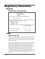
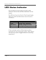
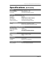
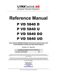
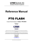
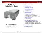
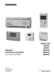
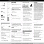
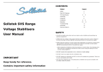
Reference Manual
R PS 5010
Series 3000 / 5000
Power Supply
© LYNX Technik AG
Brunnenweg 3
64331 Weiterstadt
Germany
www.lynx-technik.com
Reference Manual R PS 5010 Version1.1
Information in this document is subject to change without
notice. No part of this document may be reproduced or
transmitted in any form or by any means, electronic or
mechanical for any purpose, without express written permission
of LYNX Technik AG.
LYNX Technik AG may have patents, patent applications,
trademarks, copyrights or other intellectual property rights
covering the subject matter in this document. Except as
expressly written by LYNX Technik AG, the furnishing of this
document does not give you any license to patents,
trademarks, copyrights or other intellectual property of LYNX
Technik AG or any of its affiliates.
© LYNX Technik AG 2002 all rights reserved
Page 2
Reference Manual R PS 5010 Version1.1
Warranty
LYNX Technik AG warrants that the product will be free from
defects in materials and workmanship for a period of two (2)
years from the date of shipment. If this product proves defective
during the warranty period, LYNX Technik AG at its option will
either repair the defective product without charge for parts and
labor, or will provide a replacement in exchange for the
defective product.
In order to obtain service under this warranty, customer must
notify LYNX Technik of the defect before expiration of the
warranty period and make suitable arrangements for the
performance of service. Customer shall be responsible for
packaging and shipping the defective product to the service
center designated by LYNX Technik, with shipping charges
prepaid. LYNX Technik shall pay for the return of the product to
the customer if the shipment is within the country which the LYNX
Technik service center is located. Customer shall be responsible
for payment of all shipping charges, duties, taxes and any other
charges for products returned to any other locations.
This warranty shall not apply to any defect, failure, or damage
caused by improper use or improper or inadequate
maintenance and care. LYNX Technik shall not be obligated to
furnish service under this warranty a) to repair damage resulting
from attempts by personnel other than LYNX Technik
representatives to install, repair or service the product; b) to
repair damage resulting from improper use or connection to
incompatible equipment; c) to repair any damage or
malfunction caused by the use of non LYNX Technik supplies; or
d) to service a product which has been modified or integrated
with other products when the effect of such modification or
integration increases the time or difficulty servicing the product.
THIS WARRANTY IS GIVEN BY LYNX TECHNIK WITH RESPECT TO THIS
PRODUCT IN LIEU OF ANY OTHER WARRANTIES, EXPRESS OR
IMPLIED. LYNX TECHNIK AND ITS VENDORS DISCLAIM ANY IMPLIED
WARRANTIES OF MERCHANTABILITY OR FITNESS FOR A PARTICULAR
PURPOSE. LYNX TECHNIK`S RESPONISIBILITY TO REPAIR AND
REPLACE DEFECTIVE PRODUCTS IS THE SOLE AND EXCLUSIVE
REMEDY PROVIDED TO THE CUSTOMER FOR BREACH OF THIS
WARRANTY. LYNX TECHNIK AND ITS VENDORS WILL NOT BE LIABLE
FOR ANY INDIRECT, SPECIAL, INCIDENTAL, OR CONSEQUENTAL
DAMAGES IRRESPECTIVE OF WHETHER LYNX TECHNIK OR THE
VENDOR HAS ADVANCE NOTICE OF THE POSSIBILITY OF SUCH
DAMAGES.
Page 3
Reference Manual R PS 5010 Version1.1
Regulatory information
Europe
Declaration of Conformity
We
LYNX Technik AG
Brunnenweg 3
D-64331 Weiterstadt
Germany
Declare under our sole responsibility that the product
TYPE: R PS 5010
To which this declaration relates is in conformity with the following
standards (usage in environments E1 – E3):
EN 55103-1 /1996
EN 55103-2 /1996
EN 60950 /2001
Following the provisions of 89/336/EEC and 73/23/EEC directives.
Winfried Deckelmann
Bickenbach, January 2003
Place and date of issue
Legal Signature
USA
FCC 47 Part 15
This device complies with part 15 of the FCC Rules. Operation is
subject to the following two conditions: (1) This device may not
cause harmful interference, and (2) this device must accept any
interference received, including interference that may cause
undesired operation.
Note: This equipment has been tested and found to comply with the
limits for a Class A digital device, pursuant to the part 15 of the FCC
Rules. These limits are designed to provide reasonable protection
against harmful interference when the equipment is operated in a
commercial environment. This equipment generates, uses, and can
radiate radio frequency energy and, if not installed and used in
accordance with the instruction manual, may cause harmful
interference to radio communications. Operation of this equipment in
a residential area is likely to cause harmful interference in which case
the user will be required to correct the interference at his own
expense
Page 4
Reference Manual R PS 5010 Version1.1
Contents
Warranty .............................................................................................................. 3
Regulatory information ...................................................................................... 4
Europe................................................................................................................4
Declaration of Conformity ........................................................................4
USA .....................................................................................................................4
FCC 47 Part 15.............................................................................................4
Contents .............................................................................................................. 5
Getting Started.................................................................................................... 7
Packaging.........................................................................................................7
Product Description .........................................................................................7
Functional Diagram .........................................................................................8
Supply Layout ...................................................................................................8
Installation ......................................................................................................... 10
Mechanical.....................................................................................................10
Electrical Installation. .....................................................................................10
Hot Swapping............................................................................................10
Settings and Control ......................................................................................... 11
GPO Alarms ...............................................................................................11
LED Status Indicator .......................................................................................... 12
Specifications (R PS 5010)................................................................................ 13
Parts List.............................................................................................................. 14
Service ............................................................................................................... 14
Contact Information ......................................................................................... 15
Page 5
Reference Manual R PS 5010 Version1.1
This page is intentionally left blank
Page 6
Reference Manual R PS 5010 Version1.1
Getting Started
Packaging
The shipping carton and packaging materials
provide protection for the power supply during
transit. Please retain the shipping cartons in case
subsequent shipping of the product becomes
necessary.
Product Description
The R PS 5010 is a high quality Power Supply for the
R FR 5010 and R FR 3010 rack frames designed
primarily for broadcast and professional
applications.
The R PS 5010 is a sophisticated power system
designed for demanding applications. The unit
features integral microprocessor control and
sophisticated power filtering. The unit also has a
temperature controlled DC fan and onboard LED
alarm and status indication.
External alarming is possible via GPO connections
and when combined with a LYNX control system
remote status monitoring and error reporting is
possible.
When used as a pair in a rack system, full
redundancy can be achieved and the supplies are
hot swappable.
The P PS 5010 is part of the Series 3000 and 5000
ranges of modular products, which offer high
quality, modularity and flexibility for a variety of
applications
Page 7
Reference Manual R PS 5010 Version1.1
Functional Diagram
Figure 1 below is the functional diagram outlining
the power system used in the R FR 5010 and R FR
3010 rack systems.
Processing Board
DC/DC
Converter
+ 12 VDC
Digital Supplies
CHOKE
DC/DC
Converter
+ 12 VDC
Regulator
Analog Supplies
GND
GND
Redundant Power Supply ( R PS 5010 )
Voltage
Control
Temp
Control
Power Supply
Power
Filter
Control
AC IN 2
Primary Power Supply ( R PS 5010 )
Voltage
Control
Temp
Control
Power Supply
Power
Filter
Control
AC IN 1
Figure 1- Power System
Supply Layout
Figure 2 shows the physical layout of the R PS 5010
The unit is a self-contained system designed to plug
into the available slots in the R FR 3010 and R FR
5010 rack frame systems. Identical supplies are
used for Primary and Redundant use.
Page 8
Reference Manual R PS 5010 Version1.1
Side View
Second Edge Connector
here (not visible from this
angle)
NOTE
DC Fan is temperature
controlled and will only
operate when the supply
needs additional cooling
Front View
Cooling Fan
Alarm LED
Securing Screw
Figure 2 – Power Supply Layout
Page 9
Reference Manual R PS 5010 Version1.1
Installation
Mechanical
The unit is designed to slide into one of the two
available slots in the R FR 3010 and R FR 5010 rack
frame assemblies. Please refer to the reference
manuals for these items for location.
When removing and installing the supply please
ensure the front securing screw is used. (Figure 2)
This will prevent the supply from coming loose and
possibly disconnecting power. This is especially
important in mobile applications where the system
could be subject to frequent physical shocks.
NOTE
The Power supply should fit easily into the provided
slot excessive force should not be required. Please
do not “slam” the modules into the racks; this can
cause serious damage to the edge connectors
and motherboard sockets.
Electrical Installation
Hot Swapping
The power supplies support full hot swap, so it is not
necessary to remove AC power to replace a
defective Primary or Redundant R PS 5010 supply.
If the replacement supply does not function the AC
fuse for this power inlet may be defective. Refer to
the appropriate Rack Frame manuals for location
and fuse ratings.
NOTE. The DC fan is temperature controlled so
when a new supply is installed the fan will not
initially spin. This is normal
Page 10
Reference Manual R PS 5010 Version1.1
Settings and Control
There are no user setting for the R PS 5010 Power
supply, the unit is self contained and factory preset
and tested for normal operation.
GPO Alarms
The power supply will report alarms through a GPO
output provided in the Rack Frame. Please refer to
the manuals for the respective rack frame for
details on these connections.
Should a supply fault develop, the errors are
alarmed and reported in the following ways:
•
Via the LED on the located on the front of the
supply (Figure 2).
•
Via a two state GPO alarm provided on the
alarm connector on the rack frame*
•
Via the control system (if installed)
If the redundant power supply is installed, the
system will switch supplies automatically in the
event of primary supply failure, with no interruption
to the normal operation of the rack.
* Please refer to the Rack Frame manual for more
details on power supply alarms.
Page 11
Reference Manual R PS 5010 Version1.1
LED Status Indicator
The P PS 5010 Power Supply has built in LED
indicator that serves as status indication for the
supply.
The LED can found on front of the Power Supply
(figure 2) and the table below shows the error
conditions.
LED Color
Condition
Green
Yellow
Red Flashing
Red Continuous
Off
Normal Operation
Warning: High Temperature
Warning: Voltage out of range
Warning: Over Temperature
Failure: Exchange Supply
If the controller option is fitted alarms will be
reported into the monitoring system, GPO alarms
can also be used to trigger external monitoring
equipment.
Page 12
Reference Manual R PS 5010 Version1.1
Specifications
(R PS 5010)
Inputs
AC Line Voltage
AC Line Frequency
Connection
100 - 240 VAC +/- 10%
50 Hz to 60 Hz +/- 5%
Via module card edge connector
Outputs
DC Voltage
Current
Alarm Major
Alarm Minor
Alarm Common
Output Connections
12 VDC
Max 11A
Contact closure to Alarm Common
Contact closure to Alarm Common
Common for Alarm contacts
Via module card edge connector
Performance
Cooling
Normal use = convection cooling.
DC fan automatically activated if needed
Electrical Specifications
Operating Voltage
Power Consumption
Connection
Safety
12 VDC
130 W (max)
Via module card edge connector
IEC 60950/ EN 60950/VDE 0805
Mechanical
Size
Weight
260mm x 78mm x 33mm
0.5 kg
Ambient
Temperature
Humidity
+5°C to 40°C
Max 90% non condensing
Supplied Accessories
Documentation
R PS 5010 Reference Manual
Page 13
Reference Manual R PS 5010 Version1.1
Parts List
Due to the very dense design and high level of
integration there are no user serviceable electronic
assemblies within the R PS 5010 Power Supply.
R PS 5010 Power Supply (complete)
Description
Power Supply
Model Number
R PS 5010
Part Number
6.155.001.011
Service
If you are experiencing problems, or have questions
concerning your R PS 5010 Power Supply please
contact your local distributor for assistance.
We offer a fixed cost service exchange program for
defective Power Supplies out of Warranty. Please
contact your distributor or check our web site for
details on this program.
More detailed information and product updates
may be available on our web site:
www.lynx-technik.com
You will also find links to contact us directly for
assistance.
Page 14
Reference Manual R PS 5010 Version1.1
Contact Information
Please contact your local distributor; this is your
local and fastest method for obtaining support and
sales information.
LYNX Technik can be contacted directly using the
information below.
Address
LYNX Technik AG
Brunnenweg 3
64331 Weiterstadt
Germany
Website
www.lynx-technik.com
E-Mail
[email protected]
LYNX Technik manufactures a complete range of
high quality modular products for broadcast and
Professional markets, please contact your local
representative or visit our web site for more product
information.
Page 15
Reference Manual R PS 5010 Version1.1
This page is intentionally left blank
Page 16
Reference Manual R PS 5010 Version1.1
Notes
Page 17