1
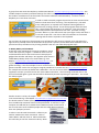
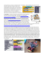
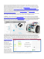
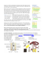
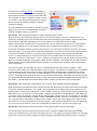
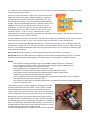
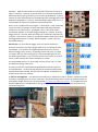
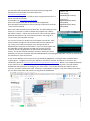
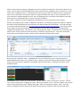
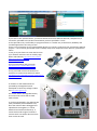
Learning to code - with a purpose Part 1
Adrian Oldknow
Jan 2015
[email protected]
1. Introduction The Turing anniversary and the release of ‘The Imitation Game’ film have helped to bring
attention to the UKs pivotal role in the development of electronic computers. The success of the Raspberry
Pi, last week’s Royal Institution’s Christmas Lectures ‘Sparks Will Fly’ and the increasing public awareness
and interest in the Internet of Things (IoT) look like stimulating the same sort of public enthusiasm for home
computing which the BBC micro achieved in the 1980s. The key difference is that the raw materials for
assembling `intelligent devices’ at home are now staggeringly cheaper, smaller and reliable than their
counterparts 30 years ago.
Part of the popular appeal of the BBC micro was that you could achieve a lot with relatively simple programs
written in a dialect of the Basic programming language. As well as outputting coloured text and graphics on
the screen you could make music and noises with the on-board speakers. It also had a `user-port’ which
could be connected both to receive inputs from sensing devices and to send outputs to control lights, motors
and other electro-mechanical devices. `Home robotics’ is not new – but it is now much more accessible.
This is also made much more possible through the Internet, e-mail and mobile communications – where you
can instantly download the software, driver, video, user-manual, help-sheets and other resources (often
free) to get you going without delay.
Whether or not you are interested in learning to control devices by writing your own programs (you are
probably far more proficient than me, anyway) you might have family members currently involved in
education 5-18 who are interested. Electronics appears in the Physics syllabus, coding appears in the
Computing syllabus and control systems appear in the Design Technology (DT) syllabus. As a STEM
Ambassador at the Winchester Science Centre I am involved in working with fellow Ambassadors from
industry in helping teachers deliver aspects of these subjects which are currently relatively unfamiliar to
them. Within the current Computing curriculum most students will encounter Scratch and Python as the
most commonly taught programing languages. Let’s start with Scratch.
2. Scratch In the early days of electronic computing, so-called `high-level programming languages’ were
developed for different applications. COBOL was developed for commercial applications, Fortran and Algol
for scientific ones and LISP for natural language ones. As part of the `Man And Computer’ MAC project at
MIT, Seymour Papert and Marvin Minsky developed a graphical programming system for a `floor turtle’ – a
wheeled robot device with a pen which can be moved up and down which was connected to the computer
by a cable. Its `turtle graphics’ commands included instruction like `Forward 5’, `Right 90’ and `Pen Up’.
They developed a programming language called `Logo’ which added a range of commands to the existing
LISP language. As cheaper graphical display devices became available, the floor turtle was replaced by a
screen simulation – usually a simple arrow-head. Scratch was an updated development from MIT about 10
years ago: http://scratch.mit.edu/about/. Developers at Berkeley redesigned the Scratch system around a new
interface called `Build Your Own Blocks’ BYOB which is now incorporated into the current Scratch release:
http://scratch.mit.edu/. Try playing the short video there to get a feel for the way the system works. Along with
many current developments the current release version is intended to be run web-based, but you can
download an offline version at: http://scratch.mit.edu/scratch2download/.
Here is a program assembled from blocks in the graphical editor. Just click on the
first command to run the program. Save it as `Hex’. Here is what Scratch produced.
Try editing the ‘turn’ command to 45 degrees. What do you need to do to complete
an octagon? Now you are a qualified de-bugger!
There are many resources to support Scratch. The
Computing At School CAS group website has many
which are relevant to the English school Computing
curriculum. You don’t have to be a teacher to
subscribe to this site, which is free.
A group from CAS wrote the Raspberry Pi Education Manual: http://www.raspberrypi.org/cas-educational-manual/. This
includes chapters written by Graham Hastings of St John’s College School in Cambridge on using Scratch. (I
also made a contribution on the free maths and science software called GeoGebra). You don’t need a
Raspberry Pi to use these resources!
In order to make a Scratch program respond to an event we need to be
able to include some form of sensing. The simplest way is, like with
many video games, to respond to the keyboard sensing whether a
particular key is being pressed. The Scratch program shows the basic
idea. The program will continue to run until the `a’ key is pressed. It
continually monitors the keyboard to see if the `space bar’ is being
pressed. When it is, then the Scratch icon spins right a little, and when it
is not then it spins left. Just click on the first statement to set Scratch
spinning and see how it responds to the keyboard.
Can you alter the program so that Scratch turns left when the left-arrow is pressed, turns right when the
right-arrow is pressed, moves forward when the up-arrow is pressed, moves back when the down-arrow is
pressed and stays still when no key is being pressed? How can you make the program stop?
3. MaKey MaKey and PicoBoard
So we have now used Scratch to control a simple on-screen
‘sense and response’ program. It would be more fun if we
could extend the idea to sense and control some physical
gadgets like switches and lamps. One popular input device is
called MaKey MaKey which costs around £50 e.g. from
Maplin: http://www.maplin.co.uk/p/makey-makey-invention-kit-n71nr. It is
supported by an extensive website of resources, projects,
guides and blogs. One fun example is how it can be used as a
games controller such as for carrying out surgical procedures on Scratch the cat! http://makeymakey.com/guides/.
For a simple test connect the board with a USB cable. Use one of the crocodile clip connector cables
supplied to connect your left hand to one of the EARTH connectors. Then touching the SPACE disk on the
front of the board lights a green LED and will be detected by Scratch as pressing the Space Bar. Test it with
this little program.
Another answer is to buy the simple control board called the Picoboard which
costs around £30 e.g. from Maplin: http://www.maplin.co.uk/p/picoboard-for-scratch-n79dp.
The board contains a slider (linear potentiometer), light sensor, audio sensor,
four crocodile clip resistance sensors and a pushbutton. It connects to your
computer via USB and has a standard micro-USB connection on the board. I
am sure that more tech-confident people than me could design and build
their own (cheaper) version!
In order to use this with the Scratch 2 software you
need to enable some extra commands. Click on
`More Blocks’ and then click on `Add an Extension’.
This will take you into the `Extension Library’ which
currently offers you a choice of `Picoboard’ and/or `LEGO WeDo’. Select Picoboard and see how this adds
some new commands to Scratch as above. The
sample program uses the slider on the Picoboard to
move Scratch forward and backwards. The slider (aka
rheostat) returns a value between 0 and 100. The
fourth command, in the shape of a long oval, returns
a number which we can use in a test (green)
statement to control an `If’ loop. There are several
other sensors on the board which return a value which can be used to control an action.
4. LEGO WeDo The other set of devices which Scratch currently supports for
sense-and-control are made by LEGO. They produce the LEGO WeDo
resource set which can be bought for around £60: http://www.amazon.co.uk/LegoEducation-WeDo-Resource-Set/dp/B006ZKVQPC. The main component of this kit is a small
block which connects to the USB port of a computer and to which you can
connect a motor and either or both of two sensors. Information about the
sensors is at: http://www.legoengineering.com/wedo-sensors/. The IR motion sensor can
detect objects very roughly up to 15 cm away, depending on the shape of the
object and other properties (reflection, colour, etc.). The tilt sensor detects
changes in position. It can detect six different positions: tilt this way, tilt that
way, tilt up, tilt down, no tilt and any tilt. LEGO has its own graphical software for sensing and control with
WeDo, but it is very expensive (c£50) and WeDo works fine with Scratch, which is free:
http://www.rapidonline.com/design-technology/lego-education-wedo-software-plus-activity-pack-300536.
To test the kit we can build a small buggy powered by the motor which responds to the motion sensor by
moving forward until it detects an object in its path and then reversing back and stopping. Better still, we
can combine it with the light sensor on the Picoboard to simulate a Mars explorer vehicle. You will need to
build a simple three-wheeled buggy from Technical Lego with the motor engaging a gear to rotate the rear
axle. The chassis supports the LEGO USB brick which connects to the motor and to the motion sensor which
sticks out in front of it like a pair of eyes. It also carries the Picoboard. As the LEGO brick and the Picoboard
both need to be connected to USB ports we won’t be able to send the vehicle on a very long voyage! Now
use the Scratch `More Blocks’ and `Add an Extension’ commands to bring in the LEGO WeDo controls to add
to the existing Picoboard controls. The Scratch program waits until the Sun rises over Mars (shine a torch at
the light sensor on the Picoboard). Then the motor starts moving the vehicle slowly forward until an object
is detected in its path. Then the vehicle stops, makes a noise and beats a stately retreat. It would be nice if
we could flash a light or two but you will have to make do with making something happen on the Scratch
screen instead!
So far we have just been exploring the `official’ Scratch approach. But needless to say there are many
ingenious people who have ‘hacked’ their way to use Scratch to interface with other devices such as the
Kinect bar, developed by Microsoft as a games’ controller: http://scratch.saorog.com/. An example of this being
used to control a pair of LEGO motors on a robot buggy is at: https://www.youtube.com/watch?v=77sH8O7ikJg and
instructions can be found at: http://scratched.gse.harvard.edu/discussions/how-do-i/controlling-2-lego-wedomotors-gestures-kinect.
So here is a challenge for the techies amongst us. Can you give us cheap and cheerful ways of building our
own Scratch-controlled systems using simple components and/or existing devices such as Kinect and/or
Nintendo’s Wii Remote Plus? Some ideas are at: http://wiiphysics.site88.net/ and http://ccite.org/CDK%20%20the%20Cambridge%20Dynamics%20Kit.pdf.
Now that we have explored the Scratch approach to programming with blocks we can find out more about
how the Blocks style of programming has been used for other robot and gadgetting systems.
5. Robotiky The first of these we will look at is the Robotiky system devised by two recent Cambridge
engineering graduates John and Matt: http://www.robotiky.com/. This was crowd-sourced through Kickstarter:
https://www.kickstarter.com/projects/robotiky/robotiky-make-coding-into-childs-play. You can get a free feel for the programming
system from the on-line sample menu at http://www.robotiky.com/. There is a step-by-step introduction which
guides you through using an on-screen simulation in the form of a grid with blocks forming a maze.The
physical unit is based on an ARM mBed microprocessor board: https://mbed.org/.
A key difference between Robotiky and the systems we have met so far is the way it can be programmed
from a computer using a USB connector but then disconnected to run autonomously without a trailing
umbilical cord! This means it has its own battery pack providing power to the unit for the mBed board, the
LEDs and the motors. The system is still under development, but as an `investor’ I am currently testing the
system. Currently the programming has to be done online in a web browser once you are registered:
https://www.robotiky.com/code/.
Drag boxes from the
Toolbox into the editor.
Once you have
developed your code
you can test it using the
on-screen simulator.
Press the Green arrow to
run the simulator.
Click on the right-most
of the four icons in the
middle of the red bar at
the top to download the compiled binary file to My Downloads. Connect the USB cable to the Robotiky unit.
Use My Computer to find the drive to which Robotiky will store programs (mine is E:).
Drag the ‘.bin’ file from Downloads to Robotiky and the white light will come
on and go off. When the transfer is complete, disconnect the USB cable from
the unit so that it is now autonomous.
When you press the on switch at the back of Robotiky you will see it perform a
quick square dance. The developers intend Robotiky to be an easy system to
use to learn how to move from writing blocks into first generating JavaScript
code, and then directly to using C++. I look forward to exploring this route!
The third of the icons in the red bar (like an eye) turns a block code program
into the underlying JavaScript.
One of the boxes on the menu is an `edit’ block –
which brings up a blank box. As you start to type a
command it offers a menu of commands matching
your initial letter. So if you type `r’ you can select
`robo.moveForward(1);’ from the menu to save typing
the whole command. Then you can edit the argument `(1)’ to e.g. `(4)’ to make
a block which moves Robotiky forward 4 units.
Similarly you are able see how Robotiky reads sensors, such as the distance
measurer, by using an `if’ block and starting to enter an `r’ into the space after
the `if’. This way we stumble across `If robo.pathAheadBlocked()’ and so we
can now re-write the basic Mars crawler program for Robotiky.
Now we are getting much closer to the heart of the sense-and-respond
mechanism, a sophisticated programmable chip called a microcontroller. One
of the commonest of these currently in use is the cheap Arduino system
developed by Italian engineers. But before tackling Arduino we will next meet a very new kid on the block the Crumble microcontroller.
6. Crumble and Sparkle The Crumble microcontroller is a recent educational project from Redfern
Electronics in Cambridgeshire developed by Joseph Birks: http://redfernelectronics.co.uk/crumble/ . It can be
purchased through Middlesex University’s Mindsets Online at £10 + VAT + pp, or as a starter kit for £20 + VAT + pp =
£29.94. This kit contains:
1 x Crumble controller
1 x Sparkle
2 x Gearboxes
8 x Crocodile Clip leads
1 x Light Dependent Resistor
1 x Microswitch
2 x Ultra-bright LEDs
1 x D.C. Buzzer
1 x Switched Battery Box
1 x USB to Micro USB lead.
Instructions & Project Suggestions
The software is a free download. It is a graphical
environment very similar to Scratch. The program
illustrated can be sent to Crumble via the USB cable –
use ‘Program’ and select `Program Crumble and Run’
to transfer it. Use the green triangle and red square
buttons to start and stop the program. Save the
program as `Blinky’.
For this example you do not need to attach any Inputs,
Outputs or Power to the Crumble board. It will just
flash its red LED for Motor 1 on and off.
Exercise 6.1 Add commands for Motor 2 to blink both the on-board LEDs.
Now we will use one of the LEDs supplied with kit as an external output. Connect a red lead to the +ve
Power Out at the top right of the Crumble controller and to the longer leg of the LED. Connect a black lead
from its shorter leg to the Input/Output connector marked A on the left side of the Crumble.
Replace the two motor commands in the program with ‘set A HI’ boxes and change the ‘HI’ in the second
one to ‘LOW’. When you run the program you will have to look hard at the LED as it is not very bright!
The power provided to the board via the USB connector is very low and not sufficient to power most of the
external outputs. So the next step is to open the black battery box and install 3 AA batteries. Notice there is
a small on/off switch on the box. This will provide the power needed to switch outputs like LEDs and
motors. It will also allow you to run the stored program on Crumble when you disconnect it from the
computer. Connect it to the Power In + and – contacts on the top left of the board. Now start the program
again and the LED should flash very brightly. While the LED is flashing, carefully pull out the USB connection
to the Crumble. The program should continue running – so you have now created an autonomous device.
Save the program.
The starter kit gives you two LEDs, two motors, a Sparkle LED board, and a buzzer as outputs. It also
provides a micro-switch and a light dependent resistor as inputs. Now we have enough power on the board
to drive the outputs we can test each of them. Open the `Blinky’ program again. Disconnect the external
LED. Use a black lead to connect the –ve output for Motor 1 to one of the tiny connectors on one of the
motors, and a red lead to connect the other to the +ve output on Crumble. Now when you run the program
you should see and hear the motor starting, running and stopping. Switch the ON/OFF button on the battery
box to OFF – you should see the on-board LED continue to flash, but the motor will no longer work.
Exercise 6.2 Add commands to make Motor 1 run forward, stop, run back and stop, repeatedly.
Now we will use the Sparkle unit with its multi-coloured LED. Disconnect any leads attached to the Crumble
except the USB and the Battery + and – leads. On the Sparkle find the hole marked with D and an arrow
pointing away. Connect this to the D port on the Crumble. Connect the hole on its left on the Sparkle with a
black lead to the –ve power out on the Crumble. Connect the last hole on the Sparkle with a red lead to the
+ve power out on the Crumble. Use the `Blinky’ program again, but this time use `set sparkle 0 to’ and select
the colour red from the palette to replace `motor 1 FORWARD at 100%’. Then use `set sparkle to’ and select
the colour black from the palette to replace ‘motor 1 STOP’. When you run the program the Sparkle’s LED
will switch to red, then off repeatedly. Save the program. With additional Sparkle units you can wire them
in a chain using three leads at a time. The next Sparkle unit will be unit 1, the next unit 2 and so on.
Exercise 6.3 Make Sparkle flash alternatively red, then yellow and then green repeatedly.
To test the buzzer connect its black lead to either of the –ve power outputs at the top of the Crumble.
Connect its red lead to one of the lettered outputs such as C. The program to switch the buzzer on and off is
exactly the same as the `Blinky’ program but with the Motor commands replaced with `Set C HI’ and `Set C
LO’. When you run the program you may have to put your ear very close to the buzzer to hear that is indeed
switching its buzzing on and off.
So we have now tested all the output units in the starter pack: onboard LED, external LED, Motor, Sparkle and Buzzer. Finally we
just need to find out how to make the input devices work. First
we’ll use the micro-switch. This has three legs marked COM, NO
and NC. Connect the black lead from the –ve power output to the
COM leg. Connect the red lead from the C output to the leg
marked NC. To sense the switch we use two IF statements. The
hole between the `if’ and `then’ words is for you to insert a test
condition such as `C is HI’ or `C is LO’. We will use the `motor’
commands just to switch on and off an on-board LED. Send and run the program. The LED should show red
until you close the switch, when it goes off.
See what difference it makes if you move the red lead from the NC leg to the NO leg. (Note: in most versions
of Scratch you can use and `If…Then…Else’ structure rather than the two `If’s we have used here.
Finally we can now test the Light Dependent Resistor. Connect one of its legs to the +ve power output and
the other to an output such as C. We can use exactly the same program as above to test it. When you send
and run it, the on-board LED should show red, but if you hold the resistor in your hand to cut off all the light
then the LED should go out.
Exercise 6.4 Modify the program so that the LED only shines when the Resistor is in the dark.
Exercise 6.5 Wire up Crumble and write a program to use the Switch attached to the input port C to switch
an external LED attached to output port B on and off so that you can the Switch as a Morse Code key.
Review.
The Crumble can be programmed using the free Redfern blocks software on a computer.
Once a program has been written it can transferred to Crumble using the USB connector.
Every program starts with a red ‘program start’ block.
Most programs will run inside a brown ‘loop forever’ block.
A program can be interrupted from the computer using the red square button.
The program can be restarted from the computer using the green triangle button.
Programs can be saved to and opened from a computer.
Once a program has been tested and debugged, the Crumble can be detached from the computer
and powered solely from the 4.5V battery pack.
The program stored in the free-standing Crumble can be stopped and started using the ON and OFF
switch on the battery box.
I will finish this short introductory guide by showing how to make
another primitive Mars crawler vehicle. I have a choice of LEGO,
K’Nex and Meccano construction kits but could also use tools to
make a chassis out of wood, plastic or card. Here is my ramshackle
vehicle using LEGO to enclose the two motors from the Crumble kit.
Below there is a close up of how the Crumble has been wired up.
The battery pack is connected to the +ve and –ve Power input ports.
The left and right motors are connected to the Motor 1 and Motor 2
ports. You will need to experiment with the way to connect the red
and black leads for each motor so that when both motors are set to
Forward they do both move the buggy forward.
In order to change direction we need to spin the motors in opposite
directions. Again you will need to work out which directions to use for a
right or a left turn. The only control we shall use is the Wait command to
determine how long to go forward, to turn and to go backwards. You will
need to do some measurements to find what distance the buggy will travel
forward or backwards in 1 second. Also to find what angle it will turn in 1
second when the motors are applied in opposite directions.
Here is a very simple linear test program. It starts with a `Wait’ command
to give you time (5 seconds) to switch the battery ON and position the
vehicle on a hard flat surface – preferably a floor! Then both motors
should work together to drive the buggy forward for 1 second. Then the
buggy stops for 1 second. Next the motors turn in different directions for
1 second. Then there is another 1 second pause before both motors drive
the buggy backwards for 1 second, before stopping – which is also the
end of the program.
Exercise 6.6 Can you make the buggy move in a square of side 1m?
Of course it would be nice if the buggy could move in response to some
sensed data. You could use the Light Dependent Resistor to control
when the buggy starts moving – by putting a black cloth over it to send
it to sleep, and only start moving when it senses enough light (like the
Sun dawning over Mars). You could wire up the micro-switch as a touch
sensor so that it backs off if it hits something in its path.
You will probably want to try some other sensors of your own – or wait
for Redfern to design some more.
So now we have seen a splendid new development from UK engineers
to help education. At this point we will pick up the thread of the Italian
Arduino development board, but also see how a Blocks-based editor can
make it much more user friendly.
7. Arduino and Engduino You will need some electronic components such as resistors, switches and LEDs.
If you don’t already have a set of your own then a very good starting point is to get the Arduino Starter Kit
from Maplin, Rapid, Amazon etc. for around £60: http://arduino.cc/en/Main/ArduinoStarterKit. This includes the basic
Arduino UNO board, a ‘breadboard’ for wiring components without soldering, a project book and lots of
lovely bits and pieces.
You will also need to download the free IDE software (integrated
development environment) from the Arduino site:
http://arduino.cc/en/Main/Software.
The common starting point is usually to write a program which turns a
LED on and off continuously.
An example is at: http://arduino.cc/en/Tutorial/Blink.
Here is the sample code with all the comments stripped out.
Once installed in the Arduino it will run the loop continuously until the
`reset’ button is pushed.
Here is the code entered into the Arduino IDE. The left hand green icon
shown as a `tick mark’ is used to compile the program into a binary
file called a `sketch’. If there are syntax errors in the code they will be
detected and shown in red in the bottom window. Our program is
correct and so has compiled correctly.
int led = 13;
void setup() {
pinMode(led, OUTPUT);
}
void loop() {
digitalWrite(led, HIGH);
delay(1000);
digitalWrite(led, LOW);
delay(1000);
}
You can now connect an Arduino to the computer and use the `tools’
menu to select the right kind of board and select which USB port to
use. Then you use the second green icon, the right-arrow, to
download your binary file to the Arduino. If you run the program with
the USB cable and the right LED and 220 ohm resistor wired up
correctly, then the program will run and the LED will blink away
merrily. The kit also contains a battery connector which clips onto a
9V battery so that you can power the board independently and unplug the USB cable. So you are now set up
for autonomous ‘sense and control’.
A very recent addition to the resources to help would-be gadgeteers is a free gift from Autodesk called
‘Project Ignite’. I suggest you leave your Arduino in the box for another 15 minutes or so and run the
introductory lesson at: https://projectignite.autodesk.com/app/project/9/lesson/43/overview/. Below is my completed attempt
at the Arduino Introduction unit. You can do everything you would normally do with a physical Arduino,
breadboard and components in wiring up your own circuits. You can also develop the Arduino code to
control it, and then simulate the result. Clicking on `Components’ brings up a tray full of device from which
you can select some LEDs and resistors to drag onto the breadboard.
Click on each resistor to bring up a dialog box to set the resistance to 220 ohms. Click on each LED to set its
colour. Click anywhere on the breadboard to create a wire and click somewhere else to connect it to. Click
on the wire to change its colour. Click and press the `Del’ key if you want to remove a wire or component.
Click on the `Code editor’ to write your code as if using the Arduino IDE. Click on `Start simulation’ to run
your code on the simulated Arduino circuit. Once its working OK you can attach a real Arduino to the USB
port and click on `Download Code’ to send it to the physical device.
This really is a fabulous tool for learning how to build and test circuits and code to control them!
Another very helpful utility is called `ArduBlocks’ and allows us to develop programs for Arduino in a Blocks
environment like Scratch before converting them into Arduino IDE code automatically. To install the utility
you need to download the files from http://blog.ardublock.com/engetting-started-ardublockzhardublock/. Don’t be put off by
all the adverts at the Sourceforge site. Just wait until the current version downloads – something like
`Ardublock-all-20130712.jar’. This will be in your `My Downloads’ folder. You will need to create some new
folders in the `Arduino’ directory which has been in installed in `My Documents’. The screen shot below
shows which you will need to create. Make sure that the Arduino IDE has been closed.
Once you have created the `tools’, `ArduBlockTool’ and `tool’ directories you can copy and paste the
downloaded file and rename it to `ardublock-all.jar’. When you open the Arduino IDE and select the Tools
menu you should see that `Ardublock’ now appears about half way down. Clicking on this opens up the
Ardublock editor:
See what the various menus on the left contain. Use the `Control’ menu to pick up the `do loop’. Use the
`Pins’ menu to pick up the `set digital pin’ block. Edit the pin number to `13’. Use the `Utilities’ menu to pick
up the `delay milliseconds’ block. Repeat these again. Open the `Number Constants’ menu. From the
second `set digital pin’ block drag the red `HIGH’ into the menu and replace it with the red `LOW’ block.
If you click on the `Upload’ button, your blocks will be turned into Arduino IDE code, compiled and, if
successful, uploaded to the Arduino board which you have specified in `Tools’.
So this provides a very useful utility to program Arduino in a similar way to the Scratch, Robotiky and
Crumble approaches we have just seen.
There is now a fantastic array of sophisticated devices you can buy to enhance your autonomous Arduino
projects. I have recently purchased some incredibly cheap such components from Amazon, posted from
China!
I have yet to put them into action but here are:
(a) a distance measurer such as used by Lego
WeDo and Robotiky: http://www.amazon.co.uk/HCSR04-Distance-Measuring-TransducerUltrasonic/dp/B006CHFLR2
(b) an accelerometer and gyroscope:
http://www.amazon.co.uk/MPU-6050-GyroscopeAccelerometer-Module-Arduino/dp/B00COD97LY
and (c) send and receive transmitters for
Arduinos to communicate with each other!
http://www.amazon.co.uk/433Mhz-transmitter-receiver-Arduinoproject/dp/B00E9OGFLQ
A variation on the Arduino board is
provided by the Engduino board
developed at University College London
UCL http://www.engduino.org/.
This comes with a rechargeable battery
and a micro-SD card as well as shedloads of LEDs.
It can be programmed in the Arduino IDE
(and presumably with ArduBlocks too).
Once the code has been debugged and
uploaded to the Engduino, it can be
detached and used autonomously. It
comes with a wide range of on-board
sensors which can collect data and store
them on the SD card.
8. Résumé
The word “coding” is often misused. Whether you write your programs in Scratch, Crumble, Robotiky,
Arduino IDE, Ardublock, Javascript, C++ or Python really doesn’t matter. The key skill is designing the
program logic (aka algorithm) to solve the problem you have posed. In all but the simplest cases, this is likely
to be an iterative process of `trial and improvement’. Tackling physical challenges involving `sense and
response’ is very powerful way to develop your programming skills, as well as helping you to understand the
way in which so many of the devices we take for granted nowadays actually work.
I hope this has provided enough (but not too much) information to get you started on what is sometimes
called `physical computing’. I hope we can develop a `community of practice’ between school, teachers,
students, parents, families, current engineers, experts and other interested parties to exchange information
and experiences, as well as to help inspire the future generation of technologists the UK needs.
I hope to follow this introduction up with a sequel containing similar information about other interesting
developments. Please give feedback on this venture. All contribution towards taking it forward will be very
gladly received! Thanks. [email protected]
14th January 2015