1
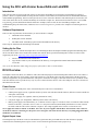
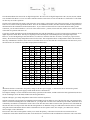
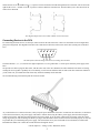
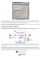
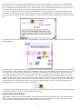
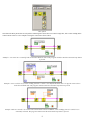
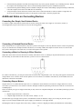
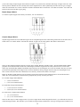
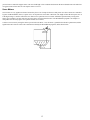
Using the Digital Control Unit (DCU) with
SensorDAQ
Vernier Software & Technology
13979 S.W. Millikan Way • Beaverton, OR 97005-2886
Toll Free (888) 837-6437 • (503) 277-2299 • FAX (503) 277-2440
[email protected] • www.vernier.com
The Digital Control Unit Manual is copyrighted ©2001-2008 by Vernier Software & Technology. All rights reserved. Purchase of the
Digital Control Unit and accompanying manual and CD includes a site license entitling the teachers at one school to reproduce the
programs, source code, and manual for use at that one school only. No part of this manual or its accompanying CD may be used or
reproduced in any other manner without written permission of Vernier Software & Technology except in the case of brief quotations
embodied in critical articles or reviews.
Vernier SensorDAQ and SensorDAQ are a trademark of Vernier. Windows is a trademark of Microsoft Corporation in the United
States and/or other countries. LabVIEW is a trademark of National Instruments, Inc. All other names mentioned are trademarks or
registered trademarks of their respective holders in the United States and other countries.
Published by
Vernier Software & Technology
13979 SW Millikan Way
Beaverton, Oregon 97005-2886
(503) 277-2299
(888) 837-6437
www.vernier.com
[email protected]
Second Edition, 2008
First Printing
Printed in the United States of America
Acknowledgements
The Digital Control Unit was designed by John Wheeler. Dr. Fred J. Thomas of mathmachines.net provided valuable suggestions for
the device. Thanks to Michele Perin, Erik Schmidt, and Sam Swartley of Vernier Software & Technology for their editing and testing.
Thanks to Adrian Oldknow for encouraging me on this project. Thanks also to Scott Webb and Eren Koont of Texas Instruments for
their ideas and encouragement on this project.
David Vernier
Vernier Software & Technology
2
Using the DCU with Vernier SensorDAQ and LabVIEW
Introduction
This reference guide is to help people who want to use the Vernier SensorDAQ to get their DCU up and running as quickly as
possible. (There is a separate manual for using the DCU with the Vernier LabPro). It assumes that the user has minimal familiarity
with LabVIEW programming. The first section provides an overview of the DCU hardware and connecting devices to the DCU, the
next section shows how to run, examine and modify one of the DCU sample VIs. The third section, Additional Notes on LabVIEW
Programming, provides information about the other DCU examples, where to look for more SensorDAQ examples, and
troubleshooting help. The final section, Additional Notes on Connecting Devices, provides a few examples of connecting devices to
the DCU.
Software Requirements
There are three steps that must be taken before you can run the DCU examples.
1.
LabVIEW software installed.
2.
NI-DAQmx software installed.
3.
The folder called “SensorDAQ” placed in the LabVIEW\user.lib directory.
These steps are outlined in the SensorDAQ User Manual
Setting Up the Files
The folder called “DCU” contains the simple drivers for controlling the DCU and sample LabVIEW programs demonstrating these
drivers. The DCU folder can be found on the CD that came with the DCU (open the SensorDAQ DCU folder) or on the Vernier
engineering web site at: engineering.vernier.com/general/software/labview/
1.
Locate or download the folder named DCU.
2.
Copy the DCU folder to your LabVIEW\user.lib directory (C:\Program Files\National Instruments\LabVIEW
x.x\user.lib)
Note: If you have Windows 2000, change the property of the folder so that it is not Read Only.
DCU Overview
The Digital Control Unit (DCU) is a small box with a short cable that plugs into the SensorDAQ DIG channel. Next to the cable is a
socket for connecting a DC power supply. On the side opposite is a 9-pin D-sub socket. The nine connections of the D-sub socket
include six digital lines, two ground connections, and a power connection. We supply a cable that connects to the 9-pin D-sub socket.
This cable has bare wires to provide an easy way for you to connect electronic devices. The color-coding for each wire is shown on a
label attached to the cable.
Power Source
The DCU requires an external power source. Four different power sources are recommended:
•
LabPro power supply (6V DC, regulated, 600 mA) [Vernier order code IPS in North America, different versions available for
other parts of the world]
•
CBL 2 power supply (6V, regulated, 300 mA) [TI Model AC 9201]
•
ULI power supply (9V, unregulated, 1000mA) [Vernier order code ULI-PS]
•
Battery power supply (one lantern battery, or a collection of four to eight 1.5-volt cells in series). To make the cable from the
batteries to the DCU, you need to use a 5.5 mm × 2.1 mm power connector (Radio Shack part number 274-1569). Connect
the leads so that the center of the connector is negative. The voltage supplied can be between 5 volts and 12 volts.
Never apply more than 12 volts DC to the DCU. Never use AC power supplies with the DCU. Note that the center connector
on the DCU socket for connecting to a DC power source is negative. The total current drawn by everything plugged into DCU
should not exceed 600 mA.
Digital Output Lines
The transparent top of the DCU reveals six red LEDs and a green LED. The green LED comes on when the DCU is properly
connected to the SensorDAQ and to a power source. Learn to check the green LED to insure proper set up.
3
The red LEDs indicate the status of the six digital output lines. We refer to the six digital output lines as D1, D2, D3, D4, D5, and D6.
You can think of the DCU as a set of six remote-controlled switches. Each of the six lines from the DCU is connected to a switch that
can have any one of three positions:
The line can be connected to the positive side of the DCU power supply, to the negative side of the power supply, or left unconnected.
There are six switches of this type inside the DCU. These are not mechanical switches, but rather electronic switches using transistors
that function like the mechanical switch illustrated above. If you connect an electrical device between the DCU line and a ground
connection, you can control whether it is on or off. If the switch is in the + position, current will flow, and the device will be on. Either
of the other two positions will turn it off.
If you have read the specifications in the documentation that came with the SensorDAQ, you may be surprised to see that there are six
digital output lines on the DCU. This may be surprising because the DIG port of SensorDAQ has only four digital output lines.
However, we do some digital logic tricks that allow us to control six, instead of four lines. Of course, we had to pay a price for this
trickery. We do not have totally independent control of all six lines. This compromise allows us independent control of the first three
lines (any combination of the three can be turned on) and then allows us to use the other three with restrictions. The easiest way to see
the restrictions is to examine the 16 possible output patterns from the DCU:
Output
0
1
2
3
4
5
6
7
8
9
10
11
12
13
14
15
D1
—
+
—
+
—
+
—
+
D2
—
—
+
+
—
—
+
+
D3
—
—
—
—
+
+
+
+
D4
—
—
—
—
—
—
—
—
—
—
+
+
+
—
—
—
—
+
+
+
+
X
X
X
X
X
X
X
X
X
X
X
X
X
X
X
X
—
+
—
D5
D6
X
X
X
X
X
X
X
X
X
X
X
X
X
X
X
X
X
X
X
X
X
X
X
X
—
—
—
+
—
+
+
+
+
indicates the line is connected to the positive voltage of the DCU power supply, — indicates the line is connected to ground
(negative lead of the DCU power supply), and X means the line is disconnected.
The outputs 0 through 11 can be considered as the binary equivalent of the number, with D1 used for the least significant bit, D2 used
for the second digit, D3 for the third, and D4 as the most significant bit.
Outputs 0 through 7 give totally independent control of the first three digital lines.
Outputs 12 through 15 are designed for controlling just D5 and D6, but do not allow any use of the first four lines. One reason for this
choice is to allow for building robot cars. With such a car, you might want one wheel to be controlled by D1 and D2, and another to be
controlled by D3 and D4. It would still be useful to have some other lines that could be used for other operations. Lines D5 and D6 do
this, but these lines can only be used when lines D1 through D4 are off. With this setup you could build a robot that can move around
using lines D1 thru D4 and then when it reaches a destination it can do a separate action. For example, you could turn on a buzzer,
turn on a light, or run a third motor.
Pairs of DCU lines can be used together to allow you to switch the polarity, or direction of current flow in an electrical device.
Consider the circuits below. Both circuits show an electrical device wired between the D1 and D2 lines of the DCU. The circuit at the
4
+
left has the D1 set for
and D2 set for —, so positive current would flow from D1 through the device and to D2. The circuit on the
right has D1 set for — and D2 set for , so positive current would flow from D2 to D1. This idea allows you to have motors run in
either of two directions.
+
Two Digital Output Lines Used to Run a Motor in Two Directions
Connecting Devices to the DCU
For connecting electrical devices, use the 9-pin, sub-D socket on the side of the DCU. There are connections for all six digital lines,
plus power and ground. The diagram below shows the connections to the holes on the socket on the cable (not the pins on the DCU
box).
The End of the Cable that Plugs into the DCU, Looking into the Holes
The holes labeled 1, 2, 3, 4, 5, and 6 are the digital output lines. G is for ground and + is for the power from the power supply of the
DCU.
We provide one cable to plug into this socket, with the color code of the wires identified on a label attached to the cable. For testing,
twisting the wires together is probably ok, but eventually you will want to solder the leads or make some other connection. Whatever
you do, make sure you insulate the leads so that they cannot accidentally touch each other.
We recommend using a terminal strip like the one shown below.
As you build devices to connect to the DCU, always keep the power limitations of the DCU in mind. For the entire DCU, it should not
exceed the current limit of your power supply. This limit is 300 mA when using the CBL 2 power supply, 600 mA when using the
LabPro power supply, and 1000 mA when using the ULI power supply. If you are using a different power supply, check the current
rating. In general, you will not damage the DCU by trying to draw too much current, but the circuit will not work properly. It may also
be possible that you could damage the power supply. The current draw for any one line should not exceed 600mA, no matter what.
Remember that Ohm’s law controls the current that flows through the device:
Current (amperes) = Voltage (volts) / Resistance (ohms)
5
In some cases you can check the resistance of the device with a meter and calculate how much current it will draw using Ohm’s law.
Refer to the Additional Notes on Connecting Devices for specific wiring examples.
Programming for the DCU
LabVIEW is a graphic programming language. LabVIEW programs are known as “Virtual Instruments”, or “VIs”. A LabVIEW VI
has two main parts: the Front Panel and the Block Diagram. The Front Panel is the user interface with buttons and controls and also
displays. The Block Diagram is the code controlling how the VI functions.
We have provided a collection of example VIs that control the DCU. If you study the Block Diagram of the DCU Example VIs you
will see that they are made up of our DCU driver subVIs that perform the low-level commands to the SensorDAQ. The three driver
subVIs that are the building blocks of many of our DCU programs, are shown below:
Wiring these driver subVIs together and providing a few inputs can easily build a simple DCU program. The inputs into the LINES 16 driver subVI determines what lines are turned on, and whether these lines are on for a set amount of time or on indefinitely.
Here is an example of inputs into the LINES 1-6 driver subVI that would turn on line 6 for 2 seconds:
Notice the number input as the “DCU Output Pattern”. This number comes from the “Output” column of the table that was introduced
in the “DCU Overview” section. The value of this number determines what line(s) is turned on and off. A value of 14 turns on line 6.
Trying out a LabVIEW Program—DCUCOUNT
To see a LabVIEW program in action, controlling the DCU, try the DCUCOUNT VI. This VI runs through all of the possible patterns
of the DCU. First, prepare your hardware:
1. Connect the DCU (with power supply) to the connector on the side of the SensorDAQ labeled DIG. Make sure this connector
locks in place.
2. Connect a SensorDAQ to the computer using the USB cable.
Now, navigate to the location of the DCU examples (C:\Program Files\National Instruments\LabVIEW
x.x\user.lib\DCU\Examples_DCU Manual). Inside you will see a number of files. Double-click on the file named DCUCOUNT.vi.
This will start LabVIEW with the DCU program open. You will see the front panel of the LabVIEW program.
6
Front Panel of DCUCOUNT.vi
Let's try running this VI. Click on the Run button (white arrow at the left side of the toolbar). This will start the VI running, and you
should see the green LED on the Front Panel labeled “SensorDAQ Connected?” turn on. Refer to the “LabVIEW Troubleshooting
Help” section of this manual if your program does not make a connection with SensorDAQ.
This program will cycle through all of the patterns of lines that are available with the DCU. Note that there are some combinations that
are not allowed (see the table of digital outputs in the “DCU Overview” section).
Examining the DCUCOUNT LabVIEW Code
Clicking on the Run button began the code that flashed all available DCU output patterns. So now let’s take a look at this code, found
in the Block Diagram (an easy way to toggle between the Front Panel and Block Diagram is to press the Control-E keys).
Block Diagram of DCUCOUNT.vi
The execution order of this program is left to right, but this is not controlled by the position of the subVIs or functions on the block
diagram. LabVIEW uses data flow programming, meaning that a subVI or LabVIEW function will not execute until all of its input
data are available.
This program has one Front Panel control, labeled “Duration”, and two Front Panel indicators, labeled “Output” and “SensorDAQ
Connected?” The Duration control sets the time that the lines remain on, and the “Output” indicator displays what output value is sent
to the DCU. The “SensorDAQ Connected?” indicator provides feedback on whether the SensorDAQ was found. The program also
has two property nodes that reset the values of the two indicators at the end of the program.
7
The SensorDAQ driver subVI, INIT, begins the program. Driver subVIs contain, and hide, a lot of low-level code. This particular
driver subVI tests for a SensorDAQ connected to the computer, initializes the SensorDAQ, and configures the device to control a
DCU. An important output of the INIT driver subVI is the “Parameters” cluster. The information in this cluster is passed to the other
driver subVIs to help them configure and control the SensorDAQ according to the setup parameters.
To view more information on the driver subVI inputs and outputs, and to see more information on the purpose of the driver subVI,
you can show the Context Help. Do this by going to the Block Diagram, choosing Help>Show Context Help from the Menu, and
placing your cursor over the driver subVI. A popup dialog box will appear. The Context Help for the INIT driver subVI will look like
this:
It is a good idea to use the Context Help to help you understand the various inputs and outputs of all of the driver subVIs and also the
LabVIEW functions.
The LINES 1-6 driver subVI is called next. It is used to turn on and off the DCU output lines. It is encased within a For Loop that will
execute 16 times. On each execution of the For Loop, the LINES 1-6 driver subVI is called, and is configured to turn on a line(s) for a
set amount of time. The amount of time that the lines are turned on is determined by the value input into the “Duration” input. The
user sets this value from a control located on the Front Panel. What line(s) is turned on is determined by the output value of the For
Loop’s iteration terminal (this is the “i” in a small blue box icon). This terminal keeps track of how many times the For Loop has
iterated and it ranges from 0 to N-1. Therefore, on the first iteration of the For Loop the value sent from the iteration terminal to the
LINES 1-6 driver subVI is 0. This turns all lines off. On the second iteration the value is 1, which turns on line 1. This is followed by a
2, which turns on line 2, a 3 which turns on lines 1 and 2, and so on, and so on, until it reaches 15. At that point all 16 DCU line
combinations have been turned on and the For Loop is terminated.
Once the For Loop has completed, the last piece of code becomes active. STOP is a driver subVI whose function is to properly end the
program, turn off any DCU lines left on, and shut down the SensorDAQ.
Using the DCU Driver SubVIs
When building or modifying a program in LabVIEW, it is easy to locate all of the DCU driver subVIs in the User Libraries function
palette. To find this palette, simply right click in the Block Diagram. If you do not know where to find the User Libraries function
palette, click on the LabVIEW function palette’s Search button and do a search for “DCU”.
8
DCU palette
Note that in the DCU palette there are sub-palettes containing DCU driver subVIs to control a single line, take a sensor reading and to
control a motor. Here are a few examples of using the various DCU driver subVIs.
Example 1: User turns line 1 on and off with a Front Panel Boolean control. The program continues until the Front Panel stop button
is pressed.
Example 2: Line 1 will turn on if a sensor reading from Ch. 1 is above a user-defined threshold. Line 1 is off if the sensor value is
below the threshold value. The program continues until the Front Panel stop button is pressed.
Example 3:The user controls a servo motor with a Front Panel control. In addition, sensor readings from Ch. 1 and Ch. 2 are
continually collected. The program continues until the Front Panel stop button is pressed.
9
Additional Notes on LabVIEW Programming
Sample Program Descriptions
The names of all the DCU manual examples we have provided start with the letters DCU and have eight or fewer characters. Below is
a list of all sample programs.
Name
DCUCAR
DCUCOUNT
DCUMASS
DCUSERVO
DCUSTEP
DCUSTEP3
DCUSUN
DCUTEMPC
DCUTOGGL
DCUWARNV
Description of Program
Digital Control Unit Programs:
Allows control of a car, driven by two DC motors, using the four arrow keys.
The program assumes your car has a DC motor powering each drive wheel.
Sends each of the 16 possible digital outputs to the DCU lines. Counts 0-15 to
show the resulting LED displays.
Turns on D1, D2, D3, and D4 in order to accelerate a magnet through a tube
(mass driver).
Controls a servo motor connected to D1.
Allows you to specify direction and number of steps for a directly-connected
stepper motor (unipolar or bipolar).
Controls a stepper motor and keeps track of stepper motor positions. This
version is best to use if you plan to use the stepper motor for several different
motions, one after the other.
Centers a light source between two light sensors using two auto-ID Vernier
light sensors connected to Ch.1 and Ch.2 and a DC motor connected to the D1
and D2 output lines of the DCU.
Creates a temperature-controlled environment. It turns on a heater (D1) if
temperature is below minimum temperature and turns on a fan (D2) if
temperature is above maximum value.
Allows you to toggle the digital lines. Use this program to test hardware that
you wire up to the DCU.
Monitors an analog signal and turns on the D1 output of the DCU if the level
exceeds a limit. This is a good sample program to start with for any project
involving monitoring an analog signal and taking action based on the reading.
In addition to these examples, you will find
further examples in the subfolder named
Examples. Open and study these simple
programs.
DCU Project Ideas
Over the years, we have used the Digital
Control Unit for dozens of projects, some
whimsical and some practical. Here are
some of the projects we have built at
Vernier. You probably have some better
ideas of your own.
•
Mass driver to accelerate a
magnet.
•
Stepper motor, DC motor, or servo
motor control system.
•
Temperature-controlled
environment.
•
Alarm system using a buzzer or
LED to warn when an event
occurs.
•
Live traps for small animals or bugs, activated by a sensor.
•
Automatic tea brewer.
•
Automated scientific instruments and demonstration equipment.
•
Light seeking to follow the sun.
•
Moving display and kinetic sculptures.
•
Automated battery tester.
•
Roving robot with sensors.
Collecting Data to Control Outputs
Some of the most interesting programs include the use of sensor data for feedback and control. Example programs that demonstrate
how to collect data from a sensor, and then perform a specific digital output based on the sensor reading, include: DCUSUN,
DCUTEMPC, and DCUWARNV.
Additional SensorDAQ Sample VIs
The SensorDAQ CD contains LabVIEW VIs that show how to program most of the major features of the SensorDAQ, including: data
collection, analog output, digital input and output, using the counter, and using other hardware on the DIG Channel. Refer to the
SensorDAQ User Manual to learn about these examples.
Using DAQmx
The DAQmx driver is at the heart of SensorDAQ control. If you are more comfortable with programming with the DAQmx drivers,
you can find DAQmx examples in the SensorDAQ folder (in the LabVIEW\user.lib directory).
LabVIEW Troubleshooting Help
•
Make sure the DCU power supply cable is attached.
10
•
If the SensorDAQ LED does not blink, the DAQmx driver may not be properly installed. Try re-installing the driver. Reboot
the computer after installing the driver. Review the SensorDAQ manual for specific installation instructions.
•
If the SensorDAQ LED is blinking, but the LabVIEW examples do not detect SensorDAQ, unplug SensorDAQ's USB cable,
reboot the computer, then reinsert the USB cable to SensorDAQ.
•
A bug in DAQmx versions between 8.6 and 8.7 turns on line 3 when the INIT driver subVI is called. To negate this, the
device is reset in the STOP subVI. However, this appears to turn on line 5 when the program ends.
Additional Notes on Connecting Devices
Connecting One Simple, Non-Polarized Device
To connect a simple, non-polarized, electrical device such as a lamp, DC motor (not a stepper or servo motor), resistor, or
electromagnet that you just want to turn on or off, use this wiring pattern:
Connecting a Polarized Electrical Device
Some electrical devices are polarized; that is, they have a positive and a negative side. They therefore must be wired in one particular
way for use with the DCU. Examples include some buzzers, a few lamps, LEDs, and complex electronic devices. For devices that
have positive and negative sides, make sure you connect the negative side to ground.
Connecting a Motor for Running in Either Direction
Simple DC motors can be wired as shown above and they will either be off or on, rotating in one particular direction. If you want to
have the ability to run the motor in either direction, you have to wire it as shown below.
For a motor wired this way, you will get one direction of rotation if D1 is high and D2 is low. You will get the opposite rotation if D2
is high and D1 is low. It will be off for all other patterns. You can connect a second motor wired this way to D3 and D4, and even a
third motor connected to D5 and D6.
Connecting Stepper Motors
Stepper motors are very different from simple “DC”or “commutator” motors that have two lead wires. Stepper motors are used in
cases where you want to have exact control of a motion. Examples include the positioning of the head on a disk drive or the laser in a
CD-ROM player.
There are basically two types of stepper motors that you may want to use: unipolar and bipolar. You can identify which type you have
with this rule:
•
Bipolar stepper motors have 4 lead wires.
•
Unipolar stepper motors have more than 4 wires, usually 5, 6, or 8.
No matter what type of stepper motor you have, remember that it needs to match the voltage you are using on your DCU power
supply. If you are using the LabPro/CBL 2 power supply you should use 6-volt stepper motors.
Identifying the leads on a stepper motor can be tricky. It helps if you have a diagram provided by the manufacturer. Unfortunately,
11
you are often using a surplus stepper motor and need to figure it out yourself. First, determine which type of stepper motor it is. Next,
look for patterns. Examine the wires carefully. Refer to the diagrams below, which symbolically show how the two types of stepper
motors are wired inside. Use a meter to measure resistance. Remember that a coil will have a few ohms of resistance. Use a little trial
and error and you will be able to get it going.
Bipolar Stepper Motors
To connect a bipolar stepper motor directly to the DCU, wire it as shown here:
Unipolar Stepper Motors
Unipolar stepper motors are more difficult to figure out for wiring than bipolar ones. Often all the ground wires are the same color or
similar colors. Use a meter and the “trial and error method” to figure out the wiring pattern. Wire them as shown below.
There are three different methods of driving a stepper motor: Normal, Half-Step, and Wave Drive. The DCUSTEP and DCUSTEP3
programs use the Normal method. In this case, electromagnets inside the stepper motor are always turned on two at a time as the
motor steps. In the Half-Step Method, intermediate steps with only one electromagnet on at a time are included. This gives you more
precision in the positioning of the stepper motor. The Wave method of driving a stepper motor has only one electromagnet on at a
time. For this reason, the Wave Drive method uses less electricity, but the motor will have less torque.
Below are the DCU output patterns to use for rotating a stepper motor clockwise and counterclockwise in each of the three drive
modes. We use the Normal drive method in all our programs, but you may want to try the others.
For “Normal” Stepper Motor Rotation:
•
5,9,10,6 for clockwise
•
6,10,9,5 for counterclockwise
For “Half-Step” Stepper Motor Rotation:
•
5,1,9,8,10,2,6,4 for clockwise
•
4,6,2,10,8,9,1,5 for counterclockwise
For “Wave Drive” Stepper Motor Rotation:
•
1, 8, 2,4 for clockwise
•
4, 2, 8, 1 for counterclockwise
There are other ways to connect stepper motors. If you use a stepper motor control integrated circuit (IC), you will need fewer wires to
control the stepper motors. This will allow you to control two stepper motors with the DCU. One type of stepper motor control IC uses
12
just two lines to control the stepper motor. One line is held high or low to indicate the direction the motor should rotate. The other line
is toggled on and off one time for each step the motor is to move.
Servo Motors
Servo motors are very popular in robotics because they have a lot of torque for their size and power used. Servo motors are controlled
by pulse-width modulation, that is, a square-wave, on-off pattern is sent to their control line. The length of time that the square wave is
at the high voltage is varied to control the servo motor rotor’s position. The servo motor will hold its position firmly as long as the
square wave continues. We can create the necessary square waveform from the DCU. The DCUSERVO program is an example. It
will produce the necessary square wave pattern for most servo motors.
Connect a servo motor by wiring the motor’s power lead to the DCU + line, the motor’s ground lead to the DCU ground line, and the
signal lead to DCU line D1. This is the connection assumed by the DCUSERVO programs, and is shown below:
13
NOTES
14